EP0801794B1 - Cartouche protectrice pour disque optique reinscriptible - Google Patents
Cartouche protectrice pour disque optique reinscriptible Download PDFInfo
- Publication number
- EP0801794B1 EP0801794B1 EP95913807A EP95913807A EP0801794B1 EP 0801794 B1 EP0801794 B1 EP 0801794B1 EP 95913807 A EP95913807 A EP 95913807A EP 95913807 A EP95913807 A EP 95913807A EP 0801794 B1 EP0801794 B1 EP 0801794B1
- Authority
- EP
- European Patent Office
- Prior art keywords
- cover
- base
- disk
- cartridge
- shutter
- Prior art date
- Legal status (The legal status is an assumption and is not a legal conclusion. Google has not performed a legal analysis and makes no representation as to the accuracy of the status listed.)
- Expired - Lifetime
Links
- 230000001681 protective effect Effects 0.000 title claims description 12
- 230000003287 optical effect Effects 0.000 title description 9
- 229920003023 plastic Polymers 0.000 claims description 15
- 239000004033 plastic Substances 0.000 claims description 13
- 230000033001 locomotion Effects 0.000 claims description 10
- 239000002184 metal Substances 0.000 claims description 9
- 210000003813 thumb Anatomy 0.000 claims description 5
- 210000003811 finger Anatomy 0.000 description 13
- 210000005069 ears Anatomy 0.000 description 9
- 230000005291 magnetic effect Effects 0.000 description 5
- 238000000465 moulding Methods 0.000 description 3
- 229910001220 stainless steel Inorganic materials 0.000 description 3
- 239000010935 stainless steel Substances 0.000 description 3
- 238000010276 construction Methods 0.000 description 2
- 238000011109 contamination Methods 0.000 description 2
- 230000005294 ferromagnetic effect Effects 0.000 description 2
- 238000002347 injection Methods 0.000 description 2
- 239000007924 injection Substances 0.000 description 2
- 238000003780 insertion Methods 0.000 description 2
- 230000037431 insertion Effects 0.000 description 2
- 238000012986 modification Methods 0.000 description 2
- 230000004048 modification Effects 0.000 description 2
- 229910000831 Steel Inorganic materials 0.000 description 1
- 239000000853 adhesive Substances 0.000 description 1
- 238000004026 adhesive bonding Methods 0.000 description 1
- 230000001070 adhesive effect Effects 0.000 description 1
- 238000013459 approach Methods 0.000 description 1
- 230000008933 bodily movement Effects 0.000 description 1
- 230000002950 deficient Effects 0.000 description 1
- 210000005224 forefinger Anatomy 0.000 description 1
- 230000006870 function Effects 0.000 description 1
- 238000004519 manufacturing process Methods 0.000 description 1
- 238000000034 method Methods 0.000 description 1
- 239000002245 particle Substances 0.000 description 1
- 230000002093 peripheral effect Effects 0.000 description 1
- 239000010959 steel Substances 0.000 description 1
- 238000003860 storage Methods 0.000 description 1
Images


Classifications
-
- G—PHYSICS
- G11—INFORMATION STORAGE
- G11B—INFORMATION STORAGE BASED ON RELATIVE MOVEMENT BETWEEN RECORD CARRIER AND TRANSDUCER
- G11B23/00—Record carriers not specific to the method of recording or reproducing; Accessories, e.g. containers, specially adapted for co-operation with the recording or reproducing apparatus ; Intermediate mediums; Apparatus or processes specially adapted for their manufacture
- G11B23/02—Containers; Storing means both adapted to cooperate with the recording or reproducing means
- G11B23/03—Containers for flat record carriers
- G11B23/0301—Details
- G11B23/0317—Containers with interchangeable record carriers
-
- G—PHYSICS
- G11—INFORMATION STORAGE
- G11B—INFORMATION STORAGE BASED ON RELATIVE MOVEMENT BETWEEN RECORD CARRIER AND TRANSDUCER
- G11B23/00—Record carriers not specific to the method of recording or reproducing; Accessories, e.g. containers, specially adapted for co-operation with the recording or reproducing apparatus ; Intermediate mediums; Apparatus or processes specially adapted for their manufacture
- G11B23/02—Containers; Storing means both adapted to cooperate with the recording or reproducing means
- G11B23/03—Containers for flat record carriers
- G11B23/0301—Details
- G11B23/0308—Shutters
Definitions
- the present invention relates generally to cartridges for data information disks.
- the invention relates more particularly to cartridges for protecting rewritable optical disks used for mass storage of alphanumeric data which may be accessed by a computer.
- a disk is preferably enclosed within a cartridge to prevent the disk from being scratched or nicked during handling.
- the cartridge containing the disk is inserted into a disk drive having an optical reader/writer and thereafter a sliding door on the cartridge is opened to expose portions of the disk to the reader/writer.
- a cartridge of this general type is disclosed in Sandell et al United States Patent 4,908,817.
- the cartridge of that patent comprises a pair of interlocking shells which define a compartment containing the disk.
- the sliding door is generally U-shaped and is formed in part by a pair of shutters which normally close access apertures formed in opposite sides of the cartridge. When the door is slid open, the shutters open the access apertures.
- one side of the disk is exposed to a rotary drive spindle of the disk drive and to a laser for reading and writing data on the disk.
- the other side of the disk is exposed to a magnetic head for erasing data from the disk.
- the Sandell et al cartridge is disadvantageous in that, for all practical purposes, the disk becomes a permanent part of the cartridge and cannot be easily removed from the cartridge and replaced with another disk.
- Suzuki et al United States Patent 4,746,013 discloses a cartridge with a hinged cover which may be opened to permit removal and replacement of a compact disc. That cartridge, however, is adapted for use only with a read-only memory (ROM) compact disc and cannot be used with an erasable or rewritable optical disk since the hinged cover does not include a shuttered aperture capable of providing access to an erasing head.
- ROM read-only memory
- a protective cartridge for data information disks comprising a base and a cover, said cover having a marginal end pivotally connected to said base for swinging movement about a predetermined axis between open and closed positions relative to said base whereby a data information disk is positionable in said base when said cover is in said open position and is enclosed by said cover and said base when said cover is in said closed position, first and second access apertures in said base and said cover, respectively, and located adjacent opposite faces of said disk, a door having a mounting portion connected to said base for relative sliding movement, said door having first and second shutters associated with said first and second access apertures respectively, said door being slidable relative to said cover and base between a first position in which each shutter shutters covers its associated access aperture and a second position in which each shutter overlies said base and said cover and exposes its associated access aperture, characterized by said door having a hinge for supporting said second shutter for swinging movement relative to said mounting portion and said first shutter about an axis parallel with said predetermined axi
- An advantage of the present invention is the provision of a protective cartridge which is capable of being easily used with different optical disks and which also is capable of permitting erasure and rewriting of the disks.
- a cartridge according to the invention can facilitate the use of less expensive optical disks.
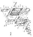
- FIGURE 1 is a perspective view of a new and improved protective cartridge incorporating the unique features of the present invention, the cover of the cartridge being shown in a closed position.
- FIGURE 2 is a view similar to Figure 1 but shows the cover in an open position and shows an optical data information disk in exploded relation with the cartridge.
- FIGURE 3 is an exploded perspective view of the cartridge and the disk.
- FIGURE 4 is a top plan view of the cartridge and shows the sliding door of the cartridge in a closed position.
- FIGURE 5 is a view similar to Figure 4 but shows the door in an open position.
- FIGURE 6 is an enlarged fragmentary cross-section taken substantially along the line 6-6 on Figure 4 and shows the cover in a latched condition.
- FIGURE 7 is a view similar to Figure 6 but shows the cover in an unlatched condition.
- FIGURE 8 is an enlarged view of certain components shown in Figure 4.
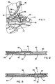
- FIG. 9 is an enlarged fragmentary cross-section taken substantially along the line 9-9 of FIG. 8 and shows the cover in a closed position.
- FIG. 10 is a view similar to FIG. 9 but shows the cover in an open position.
- FIG. 11 is an enlarged fragmentary perspective view showing the cover in an open position.
- FIG. 12 is an enlarged cross-section taken substantially along the line 12-12 of FIG. 4.
- FIG. 13 is an enlarged fragmentary cross-section taken substantially along the line 13-13 of FIG. 5.
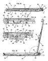
- FIG. 14 is an enlarged fragmentary cross-section taken substantially along the line 14-14 of FIG. 4 and shows the cover in a closed position.
- FIG. 15 is a view similar to FIG. 14 but shows the cover in an open position.
- FIG. 16 is an enlarged fragmentary cross-section taken substantially along the line 16-16 of FIG. 5.
- FIG. 17 is a view similar to FIG. 16 but shows the cartridge fully inserted into the disk drive.
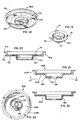
- FIG. 18 is a perspective view of a modified hub assembly.
- FIG. 19 is a perspective view of the hub of the assembly shown in FIG. 18.
- FIG. 20 is an enlarged cross-section taken axially through the hub assembly of FIG. 18.
- FIG. 21 is a cross-sectional view taken axially through yet another version of a hub assembly.
- FIG. 22 is a bottom plan view of the hub assembly shown in FIG. 21.
- FIG. 23 is a cross-sectional view taken axially through a unitary hub.
- the invention has been shown in the drawings as embodied in a protective cartridge 20 for a rewritable optical disk 21.
- the cartridge is similar to that of Sandell United States Patent 4,908,817, the disclosure of which is incorporated herein by reference.
- the cartridge 20 is especially adapted for use with a disk 21 having alphanumeric data recorded on one side thereof, the data herein being on the lower side of the disk.
- a disk 21 having alphanumeric data recorded on one side thereof, the data herein being on the lower side of the disk.
- Such a disk is considered defective if any portion of the data encoded thereon cannot be faithfully reproduced. Accordingly, it has been recognized that for storing alphanumeric data on optical disks, the disk should be contained within a protective cartridge to prevent the disk from become scratched or pitted during handling.
- the present cartridge 20 includes a single-piece base 22 which is injection molded from transparent plastic enabling the disk 21 to be seen and identified through the base.
- the base is generally rectangular in shape and includes a bottom wall 23 (FIG. 2) and upstanding side walls 24, 25 and 26 extending along three of the margins of the bottom wall.
- a fourth upstanding side wall 27 is located adjacent the rear of the base but is spaced somewhat forwardly of the rear margin of the bottom wall.
- a generally circular wall or rib 28 is formed integrally with and extends upwardly from the bottom wall 23, is located inwardly of the side walls 24-27, and defines a pocket for the disk, the latter herein being a 4-1/2" disk having approximately a 15 mm. hole 29 through the center thereof. Portions of the rib 28 are substantially tangent to portions of the side walls 24-27.
- an access aperture 30 (FIGS. 2 and 3) is formed through the bottom wall 23 of the base 22.
- the access aperture is generally U-shaped and extends in a fore-and-aft direction along the bottom wall 23 from a point somewhat beyond the center of that wall, past a notch 31 in the side wall 27, and to another upstanding wall 32 spaced rearwardly from the wall 27.
- the access aperture 30 is adapted to be selectively opened and closed and, when open, exposes the lower side of the disk 21 to a rotary disk drive 33 (FIG. 17) and also to a laser head (not shown) for recording data on and reading data from the lower side of the disk.
- an apertured cover 35 is pivotally mounted on the base 22 to swing between open and closed positions and is uniquely constructed to expose the disk 21 to a magnetic head (not shown) for erasing data from the disk.
- the disk may be easily removed from the cartridge 20 and replaced with a different disk and, in addition, the disk may be erased and rewritten as a result of the cover being apertured and capable of exposing the disk to the erasing head.
- the cover 35 includes a generally rectangular plate 36 injection molded from transparent plastic and having a tongue-like mounting portion 37 (FIG. 10) near its rear margin.
- a circular rib 38 (FIG. 2) depends from the underside of the plate 36 and, when the cover 35 is closed, fits closely inside of the rib 28 of the base 22 to help define the pocket for the disk 21.
- the front or free edge 39 and the side edges 40 and 41 of the plate lie just inside of the walls 25, 24, and 26, respectively, while the top of the plate is substantially flush with the upper edges of such walls.
- the walls 24, 25 and 26 of the base 22 rather than the plate 36 dictate the outside configuration of the cartridge 20 and, since the walls can be easily molded to a controlled size and shape, the cartridge may be freely inserted into and removed from the disk drive.
- Hinge means are provided for mounting the cover 35 for upward and downward swinging on the base 22 about a laterally extending axis between the closed and open positions of the cover.
- the hinge means are defined in part by laterally spaced pairs of laterally spaced ears 43 (FIGS. 2 and 8-11), there being one pair of ears formed integrally with and projecting rearwardly from the mounting tongue 37 adjacent each end thereof. Near their free ends, the ears of each pair are bridged by a laterally extending cylindrical pin 44 (FIGS. 9 and 10) which is integral with the ears.
- the hinge axis of the cover 35 lies substantially along a line extending through the two hinge pins and is located substantially in the plane of the plate 36.
- a separately molded and laterally extending plastic strip 45 (FIG. 3).
- the latter is secured to the base 22 by four screws 46 which are threaded into bosses 47 projecting upwardly from the bottom wall 23 of the base.
- the bosses support the strip 45 in vertically spaced relation from the bottom wall 23 with the strip being located between the upstanding walls 27 and 32.
- Each end portion of the strip 45 is formed with a finger 48 (FIGS. 8-10) which projects forwardly between the ears 43 on the adjacent end portion of the cover 35 and overlies the hinge pin 44 that spans such ears so as to captivate the pin against upward movement.
- a tab 49 is formed integrally with and projects upwardly from the bottom wall 23 and extends between each pair of ears at the forward side of the hinge pin in order to captivate the pin against forward movement.
- the cover 35 is assembled with the base 22 by placing the cover flat on the base with the hinge pins 44 located just rearwardly of the tabs 49.
- the strip 45 then is attached to the base 22 by the screws 46 to cause the fingers 48 to overlie the hinge pins 44.
- the hinge pins are captivated against bodily movement relative to the base 22 but may pivot on the base to enable the cover 35 to swing between its closed and open positions.
- Means are provided for releasably holding the cover 35 in an upright open position in order to facilitate insertion of the disk 21 into and removal of the disk from the base 22.
- such means comprise resiliently yieldable and cantilevered fingers 51 (FIGS. 8-10) molded integrally with the plastic strip 45 adjacent the outboard ear 43 of each pair of ears, each finger having a latching nib 52 on its free end.
- each nib 52 resiliently engages the outboard side of the adjacent outboard ear 43.
- each nib snaps to a latched position located in engagement with the forward side of the outboard ear (see FIG.
- the cover 35 is releasably held in its closed position by a pair of laterally spaced latches 53 (FIGS. 2, 6 and 7) molded integrally with and depending from the underside of the cover near the free edge 39 thereof.
- each latch hooks beneath a ledge 54 which forms part of a finger tab unit 55.
- Each finger tab unit is integral with the base 22 near a forward corner thereof and is resiliently cantilevered so as to be capable of flexing laterally relative to the base.
- each finger tab unit 55 is in a relaxed state and, under such conditions, the latch 53 hooks beneath the ledge 54 as shown in FIG. 6.
- the tab units By squeezing the two finger tab units 55 between the thumb and finger of one hand, the tab units are flexed inwardly to move the ledges 54 inwardly from beneath the latches 53 as shown in FIG. 7 and thereby permit opening of the cover 35.
- the latches engage the ledges and momentarily cam the finger units outwardly to allow the latches to pass by the ledges, after which the finger units spring inwardly to cause the ledges to move into hooking engagement with the latches.
- a generally V-shaped notch 57 (FIG. 2) is formed in the center portion of the wall 25 of the base 22 and in the adjacent portion of the circular rib 28.
- the notch defines an opening into which a thumb may be inserted for purposes of placing the thumb into engagement with the outer peripheral edge of the disk.
- a generally V-shaped shield 58 (FIGS. 1 and 2) is formed integrally with and depends from the central portion of the free edge 39 of the cover. When the cover is closed, the shield 58 slips into that portion of the notch 57 formed in the wall 25 of the base 22 and closes off the notch to protect against entry of dirt and the like.
- the outer side of the shield 58 is substantially flush with the outer side of the wall 25 when the cover is in its closed position.
- an access aperture 60 (FIGS. 2, 3 and 5) is formed through the swingable cover 35 in order to enable the disk 21 to be exposed to the magnetic head for erasing data from the disk.
- the access aperture 60 is generally rectangular and extends forwardly from the central portion of the rear edge of the cover to a location somewhat short of the center of the cover.
- the access apertures 30 and 60 are adapted to be selectively opened and closed by a slidable door 61 having shutters 62 and 63 (FIG. 3) which, when the door is closed, cover the access apertures 30 and 60, respectively.
- the door 61 is particularly characterized in that the shutter 63 not only is capable of sliding relative to the cover 35 between open and closed positions of the door but also is capable of swinging with the cover when the latter is opened for purposes of replacing the disk 21.
- the door 61 includes mounting means which herein consist in part of a slider in the form of a plastic member 65 (FIG. 3) which is guided for lateral movement in a channel-like track 66 at the rear end of the cartridge 20.
- the track is defined between the upper side of the bottom wall 23 of the base 22 and the lower side of the plastic strip 45.
- the slider 65 for the door 61 is essentially the same as disclosed in the aforementioned Sandell et al patent and need not be described in detail. It will suffice to say that the slider is guided in the track to slide laterally between a door-closed position shown in FIG. 12 and a door-open position shown in FIG. 13.
- a contractile spring 67 is connected between one end of the slider and a fixed pin 68 adjacent one end of the track and acts to urge the slider toward its door-closed position.
- the shutter 62 of the door 61 also is essentially the same as disclosed in the Sandell et al patent and is defined by a generally rectangular plate 70 (FIG. 3) of sheet metal (e.g., stainless steel) located in underlying relation with the bottom wall 23 of the base 22.
- the rear edge of the shutter 62 is formed with a channel-like mounting portion 71 which is attached rigidly to the slider 65 in the manner disclosed in the Sandell et al patent.
- a sheet metal retainer strip 72 (FIGS. 3 and 14) overlaps the forward edge portion of the shutter and is cemented to ledges formed in the lower side of the base.
- the shutter 63 for the upper aperture 60 also includes a generally rectangular stainless steel plate 73 (FIG. 3) which overlies the upper side of the plate 36 of the cover 35 and whose lower edge portion is slidably guided by a retainer strip 74 secured to the plate 36.
- the plate 73 of the shutter 63 is not attached directly to the plastic slider 65 but instead is attached (in a manner to be described subsequently) to a stainless steel mounting member or bracket 75 which, in turn, is attached to the slider and which, for practical purposes, forms part of the slider.
- the rear of the mounting bracket 75 is formed with a channel-shaped mounting portion 76 which is attached rigidly to the plastic slider 65 in the same manner as the mounting portion 71 of the shutter 62.
- Formed integrally with and extending forwardly from the mounting portion 76 of the bracket 75 is a tongue 77.
- Hinge means 80 connect the rear edge of the plate 73 of the shutter 63 to the forward edge of the tongue 77 of the mounting bracket 75 and support the shutter 63 for swinging upwardly and downwardly with the cover 35 about an axis coinciding substantially with the hinge axis of the cover.
- the hinge 80 is defined by a series of interleaved curls (see FIG. 3) formed along adjacent edges of the shutter plate 73 and the bracket tongue 77.
- the hinge includes a cylindrical hinge pin 84 which extends laterally through the curls so as to pivotally connect the shutter 63 to the bracket 75.
- the door 61 is disposed in a closed position (FIGS. 1 and 4) in which the shutters 62 and 63 cover the access apertures 30 and 60, respectively, to protect the disk 21 against contamination.
- a pivoted actuator arm (not shown) engages the slider 65 and moves the latter to the position shown in FIG. 13 in order to open both shutters simultaneously and thereby expose the access apertures 30 and 60 (see FIG. 5).
- the open aperture 30 exposes the disk 21 to the read/write head while the open aperture 60 exposes the disk to the erase head.
- the present cartridge 20 functions in the disk drive 33 itself in the same manner as the cartridge of the Sandell et al patent.
- the present cartridge is particularly advantageous, however, in that the hinged shutter 63 of the sliding door 61 enables the cover 35 to be hinged to the base 22 and swung to an open position facilitating easy replacement of the disk 21.
- the disk drive 33 is shown in detail in FIG. 17 and comprises a rotary pulley assembly 85, a spindle 86 which rotates in unison with the pulley assembly and an annular magnet 87 which is adhesively bonded to the pulley assembly.
- the upper end portion of the spindle is defined by a tapered tip 88.
- the cover 35 of the cartridge 20 is equipped with a floating aligner 90 which allows a precisely centered relation to be established between the axis of the disk 21 and the axis of the spindle 86 when the cartridge is inserted into the disk drive 33.
- the aligner 90 being built into the cover 35, the significant expense of gluing or otherwise securing separate alignment hubs to the disk 21 itself is eliminated.
- the aligner 90 includes a steel hub 91 (FIGS. 16 and 17) of circular cross-section and having a downwardly tapered and frustoconical lower end portion and a cylindrical upper end portion.
- the cylindrical upper end portion of the hub is sized to telescope snugly and precisely into the hole 29 in the disk 21.
- a hole 92 is formed in the axially facing lower end of the hub 91 which is sized to snugly and precisely receive the tip 88 of the spindle 86 when the cartridge 20 is inserted into the disk drive 33.
- Formed integrally with the upper end of the hub 91 is a circular plate 93 whose upper end includes a radially outwardly extending flange 94.
- the aligner 90 is adapted to be inserted into an opening 95 (FIGS. 3 and 16) formed through the central portion of the cover 35, the diameter of the opening being substantially greater than the diameter of the flange 94.
- Formed integrally with and projecting radially inwardly from the lower edge portion of the opening 95 are several (e.g.,eight) angularly spaced tabs 96 which underlie the flange 94 and support the aligner 90 vertically when the cartridge 20 is not in the disk drive 33.
- the diameter of the circle defined by the free edges of the tabs 96 is substantially greater than the diameter of the plate 93 and thus the aligner is free to float radially relative to the cover 35 as permitted by the radial clearance between the plate and the tabs.
- the aligner 90 is held in assembled relation with the cover 35 by a sheet metal cap 97 (FIGS. 3 and 16) which is bonded by a ring 98 of double-sided adhesive within an enlarged counterbore 99 formed in the upper side of the cover 35.
- a sheet metal cap 97 (FIGS. 3 and 16) which is bonded by a ring 98 of double-sided adhesive within an enlarged counterbore 99 formed in the upper side of the cover 35.
- the axial spacing between the cap 97 and the tabs 96 is significantly greater than the axial thickness of the flange 94 and thus the aligner 90 also is free to float axially relative to the cover 35.
- the hub 91 of the aligner 90 telescopes into the hole 29 in the disk 21 and establishes a precisely concentric relationship between the disk and the hub.
- the disk Prior to insertion of the cartridge into the disk drive 33, the disk rests on the base 22 of the cartridge as shown in FIG. 16 while the flange 94 rests on the tabs 96.
- the cartridge 20 is inserted into the disk drive 33 by lowering the cartridge downwardly toward the pulley assembly 85 and the spindle 86.
- the hole 92 in the hub 91 moves into telescoped relation with the spindle 86 and, because the hub is free to float radially, the hub is brought into precise concentricity with the spindle and the pulley assembly 85.
- the disk 21 engages and is stopped by the upper side of the pulley assembly 85 but the base 22 continues to move downwardly through a short distance so as to establish axial running clearance between the disk and the base as shown in FIG. 17.
- the hub 91 engages and is stopped by the magnet 87 and, as the cover 35 continues to move downwardly, axial running clearance is established between the lower side of the flange 94 and the upper sides of the tabs 96.
- the magnet 87 attracts the hub 91 and causes the disk 21 to become clamped between the lower side of the plate 93 and the upper side of the pulley assembly 85.
- the radially floatable aligner 90 serves as a means for precisely centering the disk 21 relative to the spindle 86 and for causing the disk to become rigidly clamped to the pulley assembly 85. Because the aligner also is capable of floating axially, axial clearance is established between the disk 21 and the base 22 on the one hand and between the flange 94 and the tabs 96 on the other hand so as to prevent those components from rubbing against one another during rotation of the disk.
- FIGS. 18-20 show an aligner 90A in which the hub 91A is stamped from sheet metal and includes a radially outwardly projecting flange 100 with upwardly extending and angularly spaced tabs 101.
- the flange 100 of the hub 91A is insert molded into a plastic carrier 102 having a plate 103 and a flange 104 corresponding generally to the plate 93 and the flange 94, respectively, of the first embodiment.
- the tabs 101 become encapsulated by and embedded in the plastic of the plate 103 in order to anchor the hub 91 to the carrier 102.
- FIGS. 21 and 22 show an even less costly aligner 90B in which the hub 91B, the plate 103B and the flange 104B are formed by a one-piece unit molded of highly wear-resistant plastic.
- a ferromagnetic disc 105 having a central aperture 106 is affixed to the lower end of the hub either by insert molding or by adhesively bonding the disc to the hub.
- the aligner 90C shown in FIG. 23 is molded entirely from wear-resistant plastic which is impregnated with ferromagnetic particles.
- the aligner 90C is a very inexpensive single-piece unit. If higher magnetic properties are required, a disc similar to the disc 105 may be affixed to the lower end of the hub 91C of the aligner 90C.
Landscapes
- Optical Record Carriers And Manufacture Thereof (AREA)
- Holding Or Fastening Of Disk On Rotational Shaft (AREA)
- Packaging For Recording Disks (AREA)
Claims (6)
- Cartouche protectrice (20) pour des disques d'informations de données, ladite cartouche (20) comportant une embase (22) et un couvercle (35), ledit couvercle (35) ayant une extrémité marginale reliée de façon pivotante à ladite embase (22) pour effectuer un mouvement de basculement autour d'un axe prédéterminé entre des positions ouverte et fermée par rapport à ladite embase (22) grâce à quoi un disque (21) d'informations de donnée peut être positionné dans ladite embase (22) lorsque ledit couvercle (35) est dans ladite position ouverte et est renfermé par ledit couvercle (35) et ladite embase (22) lorsque ledit couvercle (35) est dans ladite position fermée, des première et seconde ouvertures d'accès (30, 60) dans ladite embase (22) et ledit couvercle (35), respectivement, situées de façon à être adjacentes à des faces opposées dudit disque (21), une porte (61) ayant une partie de montage (65, 71, 75) reliée à ladite embase (22) pour effectuer un mouvement relatif de coulissement, ladite porte (61) ayant des premier et second obturateurs (62, 63) associés auxdites première et seconde ouvertures d'accès (30, 60), respectivement, ladite porte (61) pouvant coulisser par rapport audit couvercle (35) et à ladite embase (22) entre une première position dans laquelle chacun des éléments obturateurs (62, 63) recouvre son ouverture d'accès associée (30, 60) à une seconde position dans laquelle chaque obturateur (62, 63) s'étend au-dessus de ladite embase (22) et dudit couvercle (35) et met à découvert son ouverture d'accès associée (30, 60), caractérisée en ce que ladite porte (61) comporte une charnière (80) destinée à supporter ledit second obturateur (63) pour effectuer un mouvement de basculement par rapport à ladite partie de montage (65, 71, 75) et audit premier obturateur (62) autour d'un axe parallèle audit axe prédéterminé, dans lequel ledit second obturateur (63) peut être déplacé simultanément par rapport à ladite partie de montage (65, 71, 75) lorsqu'on fait basculer ledit couvercle (35) entre ses positions ouverte et fermée.
- Cartouche protectrice selon la revendication 1, dans laquelle ladite partie de montage (65, 71, 75) comprend un coulisseau (65) mobile par rapport à ladite embase (22) et au couvercle (35) suivant un trajet linéaire s'étendant sensiblement parallèlement audit axe prédéterminé, ladite charnière (80) reliant de façon pivotante ledit second obturateur (63) audit coulisseau (65).
- Cartouche protectrice selon la revendication 2, dans laquelle ladite embase (22) comprend un chemin (66), ledit coulisseau (65) comprenant un élément en matière plastique pouvant coulisser dans ledit chemin (66), lesdits obturateurs (62, 63) étant formés d'éléments en métal en feuille, reliés auxdits éléments en matière plastique et mobiles avec eux, lesdits éléments en métal en feuille définissant une paire de bords adjacents formés de façon à comporter des parties recourbées imbriquées entre elles, et ladite charnière (80) comprenant une broche (84) de charnière s'étendant à travers lesdites parties recourbées pour relier de façon pivotante lesdits bords adjacents des éléments en métal en feuille.
- Cartouche protectrice selon la revendication 1, comprenant en outre un élément d'alignement globalement circulaire (90) supporté par ledit couvercle (35) pour limiter le flottement radial et axial, ledit élément d'alignement (90) ayant un moyeu qui s'ajuste télécospiquement et étroitement dans une ouverture dudit disque (21) lorsque ledit disque (21) est dans ladite embase (22) et lorsque ledit couvercle (35) est dans ladite position fermée, ledit moyeu (91) étant de section transversale circulaire et ayant une extrémité tournée axialement, et un trou (92) s'étendant axialement formé dans ledit moyeu (91) et débouchant axialement à l'extérieur de son extrémité tournée axialement pour recevoir la broche (86) de l'unité à disque rotatif (38).
- Cartouche protectrice selon la revendication 4, dans laquelle ledit moyeu est mis à découvert par ladite première ouverture d'accès (30) lorsque ledit couvercle (35) est dans sa position fermée et que ledit premier obturateur (62) est dans sa position ouverte.
- Cartouche protectrice selon la revendication 1, dans laquelle ladite embase (22) est globalement rectangulaire et comprend une paroi inférieure (23) et des parois latérales (24, 25, 26, 27) s'étendant vers le haut depuis ladite paroi inférieure (23), une paroi globalement circulaire (28) s'étendant vers le haut depuis ladite paroi inférieure (23) vers l'intérieur desdites parois latérales (24, 25, 26, 27) et définissant un logement pour ledit disque, une partie de ladite paroi circulaire (28) étant placée de façon à être étroitement adjacente à une partie de l'une desdites parois latérales (25), une encoche (57) pour le pouce s'ouvrant vers le haut, formée dans lesdites parties de paroi et définissant une ouverture dans laquelle le pouce peut être introduit pour s'appliquer contre le bord dudit disque (21) pendant que ledit disque (21) est enlevé de ladite embase (22), ledit couvercle (35) ayant un bord libre (39) et un écran (58) faisant saillie vers le bas du bord libre (39) dudit couvercle et dimensionné pour s 'ajuster dans, et fermer sensiblement, ladite encoche (57) à proximité immédiate de ladite première paroi latérale (25) lorsque ledit couvercle (35) est dans ladite position fermée.
Applications Claiming Priority (3)
| Application Number | Priority Date | Filing Date | Title |
|---|---|---|---|
| US21087294A | 1994-03-18 | 1994-03-18 | |
| US210872 | 1994-03-18 | ||
| PCT/US1995/003583 WO1995026027A1 (fr) | 1994-03-18 | 1995-03-20 | Cartouche protectrice pour disque optique reinscriptible |
Publications (3)
| Publication Number | Publication Date |
|---|---|
| EP0801794A1 EP0801794A1 (fr) | 1997-10-22 |
| EP0801794A4 EP0801794A4 (fr) | 1997-12-17 |
| EP0801794B1 true EP0801794B1 (fr) | 2001-08-29 |
Family
ID=22784620
Family Applications (1)
| Application Number | Title | Priority Date | Filing Date |
|---|---|---|---|
| EP95913807A Expired - Lifetime EP0801794B1 (fr) | 1994-03-18 | 1995-03-20 | Cartouche protectrice pour disque optique reinscriptible |
Country Status (6)
| Country | Link |
|---|---|
| US (1) | US5793742A (fr) |
| EP (1) | EP0801794B1 (fr) |
| JP (1) | JPH09510815A (fr) |
| CA (1) | CA2185452A1 (fr) |
| DE (1) | DE69522472T2 (fr) |
| WO (1) | WO1995026027A1 (fr) |
Families Citing this family (27)
| Publication number | Priority date | Publication date | Assignee | Title |
|---|---|---|---|---|
| JP3491427B2 (ja) * | 1996-02-09 | 2004-01-26 | ソニー株式会社 | ディスクカートリッジ |
| JP3666111B2 (ja) * | 1996-03-21 | 2005-06-29 | ソニー株式会社 | 円盤状光記録媒体 |
| MY122078A (en) * | 1996-10-02 | 2006-03-31 | Sony Corp | Disk cartridge |
| TW385433B (en) | 1996-10-28 | 2000-03-21 | Dainippon Printing Co Ltd | A cartridge case for a disk-shaped recording medium and a disk cartridge |
| US6157517A (en) * | 1996-10-30 | 2000-12-05 | Dai Nippon Printing Co., Ltd | Shutter mechanism for disk cartridge |
| EP0843310A1 (fr) * | 1996-11-18 | 1998-05-20 | TDK Corporation | Cassette à disque |
| US6118757A (en) * | 1997-02-26 | 2000-09-12 | Opticord, Inc. | Data information disk cartridge and method of assembly and use |
| JPH10302426A (ja) * | 1997-04-28 | 1998-11-13 | Sony Corp | ディスクカートリッジ |
| EP0928483A1 (fr) * | 1997-07-24 | 1999-07-14 | Sony Corporation | Boitier pour support d'enregistrement de type disque |
| US6269074B1 (en) | 1997-07-24 | 2001-07-31 | Sony Corporation | Container casing for disc-shaped recording medium |
| JPH1166791A (ja) * | 1997-08-13 | 1999-03-09 | Sony Corp | ディスクカセット |
| US6185069B1 (en) * | 1997-08-29 | 2001-02-06 | Iomega Corporation | Magnetic disk cartridge having a flexible disk anti-drift mechanism |
| US7227817B1 (en) | 1999-12-07 | 2007-06-05 | Dphi Acquisitions, Inc. | Low profile optical head |
| US6580683B1 (en) | 1999-06-23 | 2003-06-17 | Dataplay, Inc. | Optical recording medium having a master data area and a writeable data area |
| US7191153B1 (en) | 1999-09-10 | 2007-03-13 | Dphi Acquisitions, Inc. | Content distribution method and apparatus |
| US6631359B1 (en) | 1999-09-10 | 2003-10-07 | Dphi Acquisitions, Inc. | Writeable medium access control using a medium writeable area |
| JP2001250359A (ja) * | 1999-12-27 | 2001-09-14 | Dainippon Printing Co Ltd | ディスクカートリッジ |
| US6572205B2 (en) * | 2000-05-09 | 2003-06-03 | Sony Computer Entertainment Inc. | Electronic device cabinet and electronic device |
| JP3293817B2 (ja) * | 2000-05-09 | 2002-06-17 | 株式会社ソニー・コンピュータエンタテインメント | 電子機器用筐体および電子機器 |
| JP2003085910A (ja) * | 2001-09-11 | 2003-03-20 | Sony Corp | ディスクカートリッジ、ディスク記録媒体装置及びディスク記録再生装置 |
| KR100850704B1 (ko) * | 2002-02-19 | 2008-08-06 | 삼성전자주식회사 | 디스크 카트리지 |
| US7263706B2 (en) | 2002-02-19 | 2007-08-28 | Samsung Electronics Co., Ltd. | Disk cartridge and disk player using the same |
| JP4355145B2 (ja) * | 2002-02-26 | 2009-10-28 | 三菱化学メディア株式会社 | センタリングのための孔を有するカートリッジ型記録媒体 |
| US7108129B2 (en) | 2003-10-10 | 2006-09-19 | Enxnet, Inc. | Optical disk storage case with blocking tongue |
| US7555764B2 (en) * | 2004-02-26 | 2009-06-30 | Panasonic Corporation | Cartridge and shutter used in the same |
| JP4940964B2 (ja) * | 2007-01-26 | 2012-05-30 | 船井電機株式会社 | 電子機器の筐体及び液晶テレビジョン受像器 |
| CN116337880B (zh) * | 2023-05-29 | 2023-08-11 | 中山市美速光电技术有限公司 | 一种用于光纤阵列加工过程的智能图像监控系统 |
Family Cites Families (12)
| Publication number | Priority date | Publication date | Assignee | Title |
|---|---|---|---|---|
| US4694448A (en) * | 1984-05-15 | 1987-09-15 | Nippon Gakki Seizo Kabushiki Kaisha | Disc case |
| US4669078A (en) * | 1984-07-04 | 1987-05-26 | Nippon Gakki Seizo Kabushiki Kaisha | Disc case |
| US4702369A (en) * | 1986-01-31 | 1987-10-27 | Cinram Ltd./Ltee. | Storage container for records or the like |
| US4746013A (en) * | 1986-09-16 | 1988-05-24 | Sony Corporation | Disc cartridge with releasable locking means |
| US4908817A (en) * | 1986-11-14 | 1990-03-13 | Opticord, Inc. | Cartridge for optical data discs |
| JPS63122955U (fr) * | 1987-02-02 | 1988-08-10 | ||
| NL8802185A (nl) * | 1988-09-05 | 1990-04-02 | Philips Nv | Schijfcassette. |
| JPH0268378U (fr) * | 1988-11-11 | 1990-05-23 | ||
| CH686538A5 (fr) * | 1992-05-15 | 1996-04-15 | Cd Plant Tecval S A | Cassette a disque. |
| US5268808A (en) * | 1992-12-14 | 1993-12-07 | International Business Machines Corporation | Disk cartridges made from unitary blanks |
| GB9307293D0 (en) * | 1993-04-07 | 1993-06-02 | Newell Terence J | Optical compact disc sotrage and loading cassette |
| TW238381B (en) * | 1993-10-29 | 1995-01-11 | Ibm | Optical data storage cartridge system |
-
1995
- 1995-03-20 WO PCT/US1995/003583 patent/WO1995026027A1/fr active IP Right Grant
- 1995-03-20 DE DE69522472T patent/DE69522472T2/de not_active Expired - Fee Related
- 1995-03-20 JP JP7524797A patent/JPH09510815A/ja active Pending
- 1995-03-20 CA CA002185452A patent/CA2185452A1/fr not_active Abandoned
- 1995-03-20 EP EP95913807A patent/EP0801794B1/fr not_active Expired - Lifetime
-
1997
- 1997-08-11 US US08/909,237 patent/US5793742A/en not_active Expired - Fee Related
Also Published As
| Publication number | Publication date |
|---|---|
| US5793742A (en) | 1998-08-11 |
| EP0801794A4 (fr) | 1997-12-17 |
| EP0801794A1 (fr) | 1997-10-22 |
| DE69522472D1 (de) | 2001-10-04 |
| WO1995026027A1 (fr) | 1995-09-28 |
| DE69522472T2 (de) | 2002-04-04 |
| JPH09510815A (ja) | 1997-10-28 |
| CA2185452A1 (fr) | 1995-09-28 |
Similar Documents
| Publication | Publication Date | Title |
|---|---|---|
| EP0801794B1 (fr) | Cartouche protectrice pour disque optique reinscriptible | |
| US4443874A (en) | Information-disc cassette | |
| US4131199A (en) | Record disk cartridge | |
| US5475674A (en) | Disc case for removably housing data discs | |
| US5903542A (en) | Protective cartridge for rewritable optical disk | |
| JP2979592B2 (ja) | ディスクカートリッジ | |
| JPH07320359A (ja) | 光ディスクカートリッジ及び光ディスクドライブ装置 | |
| EP1437735B1 (fr) | Cartouche pour disques echangeables | |
| EP1443513B1 (fr) | Cartouche destinee a recevoir un support d'enregistrement | |
| EP0982729B1 (fr) | Cassette à disque | |
| EP0645045B1 (fr) | Cassette de stockage et de chargement de disques compacts optiques | |
| US5970045A (en) | Optical disc and disc cartridge | |
| US5963538A (en) | Disk cartridge | |
| US5570341A (en) | Method of assembling disk cartridge with one-piece plastic molded door | |
| US4573096A (en) | Clam-shell cartridge for recording disc | |
| CN101681659B (zh) | 盘盒 | |
| EP1440442B1 (fr) | Cartouche de disque | |
| US5680284A (en) | Center core and shutter for a high density magnetic disk cartridge | |
| JP2001023332A (ja) | フロッピーディスク | |
| JP2526421Y2 (ja) | ディスクカートリッジ | |
| CN2331060Y (zh) | 3.5英寸可录式磁光型光盘清洁装置 | |
| JP2557886Y2 (ja) | ディスクカートリッジ | |
| JPH09543U (ja) | ディスクカートリッジの記録再生装置内での位置決め装置 | |
| KR20060126423A (ko) | 디스크 카트리지 | |
| JPS6142789A (ja) | デイスクカ−トリツジ |
Legal Events
| Date | Code | Title | Description |
|---|---|---|---|
| PUAI | Public reference made under article 153(3) epc to a published international application that has entered the european phase |
Free format text: ORIGINAL CODE: 0009012 |
|
| 17P | Request for examination filed |
Effective date: 19961010 |
|
| AK | Designated contracting states |
Kind code of ref document: A1 Designated state(s): DE FR GB NL |
|
| A4 | Supplementary search report drawn up and despatched |
Effective date: 19971030 |
|
| AK | Designated contracting states |
Kind code of ref document: A4 Designated state(s): DE FR GB NL |
|
| 17Q | First examination report despatched |
Effective date: 19981127 |
|
| GRAG | Despatch of communication of intention to grant |
Free format text: ORIGINAL CODE: EPIDOS AGRA |
|
| GRAG | Despatch of communication of intention to grant |
Free format text: ORIGINAL CODE: EPIDOS AGRA |
|
| GRAH | Despatch of communication of intention to grant a patent |
Free format text: ORIGINAL CODE: EPIDOS IGRA |
|
| GRAH | Despatch of communication of intention to grant a patent |
Free format text: ORIGINAL CODE: EPIDOS IGRA |
|
| GRAA | (expected) grant |
Free format text: ORIGINAL CODE: 0009210 |
|
| AK | Designated contracting states |
Kind code of ref document: B1 Designated state(s): DE FR GB NL |
|
| REF | Corresponds to: |
Ref document number: 69522472 Country of ref document: DE Date of ref document: 20011004 |
|
| ET | Fr: translation filed | ||
| REG | Reference to a national code |
Ref country code: GB Ref legal event code: IF02 |
|
| PLBE | No opposition filed within time limit |
Free format text: ORIGINAL CODE: 0009261 |
|
| STAA | Information on the status of an ep patent application or granted ep patent |
Free format text: STATUS: NO OPPOSITION FILED WITHIN TIME LIMIT |
|
| 26N | No opposition filed | ||
| PGFP | Annual fee paid to national office [announced via postgrant information from national office to epo] |
Ref country code: FR Payment date: 20030310 Year of fee payment: 9 |
|
| PGFP | Annual fee paid to national office [announced via postgrant information from national office to epo] |
Ref country code: GB Payment date: 20030319 Year of fee payment: 9 |
|
| PGFP | Annual fee paid to national office [announced via postgrant information from national office to epo] |
Ref country code: NL Payment date: 20030327 Year of fee payment: 9 Ref country code: DE Payment date: 20030327 Year of fee payment: 9 |
|
| PG25 | Lapsed in a contracting state [announced via postgrant information from national office to epo] |
Ref country code: GB Free format text: LAPSE BECAUSE OF NON-PAYMENT OF DUE FEES Effective date: 20040320 |
|
| PG25 | Lapsed in a contracting state [announced via postgrant information from national office to epo] |
Ref country code: NL Free format text: LAPSE BECAUSE OF NON-PAYMENT OF DUE FEES Effective date: 20041001 Ref country code: DE Free format text: LAPSE BECAUSE OF NON-PAYMENT OF DUE FEES Effective date: 20041001 |
|
| GBPC | Gb: european patent ceased through non-payment of renewal fee |
Effective date: 20040320 |
|
| PG25 | Lapsed in a contracting state [announced via postgrant information from national office to epo] |
Ref country code: FR Free format text: LAPSE BECAUSE OF NON-PAYMENT OF DUE FEES Effective date: 20041130 |
|
| NLV4 | Nl: lapsed or anulled due to non-payment of the annual fee |
Effective date: 20041001 |
|
| REG | Reference to a national code |
Ref country code: FR Ref legal event code: ST |