EP0800985A2 - Schutzkappensystem für Fahrradkabel - Google Patents
Schutzkappensystem für Fahrradkabel Download PDFInfo
- Publication number
- EP0800985A2 EP0800985A2 EP97302279A EP97302279A EP0800985A2 EP 0800985 A2 EP0800985 A2 EP 0800985A2 EP 97302279 A EP97302279 A EP 97302279A EP 97302279 A EP97302279 A EP 97302279A EP 0800985 A2 EP0800985 A2 EP 0800985A2
- Authority
- EP
- European Patent Office
- Prior art keywords
- section
- cap
- cable
- protective cap
- protective
- Prior art date
- Legal status (The legal status is an assumption and is not a legal conclusion. Google has not performed a legal analysis and makes no representation as to the accuracy of the status listed.)
- Granted
Links
Images
Classifications
-
- F—MECHANICAL ENGINEERING; LIGHTING; HEATING; WEAPONS; BLASTING
- F16—ENGINEERING ELEMENTS AND UNITS; GENERAL MEASURES FOR PRODUCING AND MAINTAINING EFFECTIVE FUNCTIONING OF MACHINES OR INSTALLATIONS; THERMAL INSULATION IN GENERAL
- F16C—SHAFTS; FLEXIBLE SHAFTS; ELEMENTS OR CRANKSHAFT MECHANISMS; ROTARY BODIES OTHER THAN GEARING ELEMENTS; BEARINGS
- F16C1/00—Flexible shafts; Mechanical means for transmitting movement in a flexible sheathing
- F16C1/10—Means for transmitting linear movement in a flexible sheathing, e.g. "Bowden-mechanisms"
- F16C1/107—Sealing details
-
- B—PERFORMING OPERATIONS; TRANSPORTING
- B62—LAND VEHICLES FOR TRAVELLING OTHERWISE THAN ON RAILS
- B62J—CYCLE SADDLES OR SEATS; AUXILIARY DEVICES OR ACCESSORIES SPECIALLY ADAPTED TO CYCLES AND NOT OTHERWISE PROVIDED FOR, e.g. ARTICLE CARRIERS OR CYCLE PROTECTORS
- B62J23/00—Other protectors specially adapted for cycles
-
- F—MECHANICAL ENGINEERING; LIGHTING; HEATING; WEAPONS; BLASTING
- F16—ENGINEERING ELEMENTS AND UNITS; GENERAL MEASURES FOR PRODUCING AND MAINTAINING EFFECTIVE FUNCTIONING OF MACHINES OR INSTALLATIONS; THERMAL INSULATION IN GENERAL
- F16C—SHAFTS; FLEXIBLE SHAFTS; ELEMENTS OR CRANKSHAFT MECHANISMS; ROTARY BODIES OTHER THAN GEARING ELEMENTS; BEARINGS
- F16C2326/00—Articles relating to transporting
- F16C2326/20—Land vehicles
-
- F—MECHANICAL ENGINEERING; LIGHTING; HEATING; WEAPONS; BLASTING
- F16—ENGINEERING ELEMENTS AND UNITS; GENERAL MEASURES FOR PRODUCING AND MAINTAINING EFFECTIVE FUNCTIONING OF MACHINES OR INSTALLATIONS; THERMAL INSULATION IN GENERAL
- F16C—SHAFTS; FLEXIBLE SHAFTS; ELEMENTS OR CRANKSHAFT MECHANISMS; ROTARY BODIES OTHER THAN GEARING ELEMENTS; BEARINGS
- F16C2326/00—Articles relating to transporting
- F16C2326/20—Land vehicles
- F16C2326/28—Bicycle propulsion, e.g. crankshaft and its support
-
- Y—GENERAL TAGGING OF NEW TECHNOLOGICAL DEVELOPMENTS; GENERAL TAGGING OF CROSS-SECTIONAL TECHNOLOGIES SPANNING OVER SEVERAL SECTIONS OF THE IPC; TECHNICAL SUBJECTS COVERED BY FORMER USPC CROSS-REFERENCE ART COLLECTIONS [XRACs] AND DIGESTS
- Y10—TECHNICAL SUBJECTS COVERED BY FORMER USPC
- Y10T—TECHNICAL SUBJECTS COVERED BY FORMER US CLASSIFICATION
- Y10T74/00—Machine element or mechanism
- Y10T74/20—Control lever and linkage systems
- Y10T74/20396—Hand operated
- Y10T74/20402—Flexible transmitter [e.g., Bowden cable]
- Y10T74/2045—Flexible transmitter [e.g., Bowden cable] and sheath support, connector, or anchor
-
- Y—GENERAL TAGGING OF NEW TECHNOLOGICAL DEVELOPMENTS; GENERAL TAGGING OF CROSS-SECTIONAL TECHNOLOGIES SPANNING OVER SEVERAL SECTIONS OF THE IPC; TECHNICAL SUBJECTS COVERED BY FORMER USPC CROSS-REFERENCE ART COLLECTIONS [XRACs] AND DIGESTS
- Y10—TECHNICAL SUBJECTS COVERED BY FORMER USPC
- Y10T—TECHNICAL SUBJECTS COVERED BY FORMER US CLASSIFICATION
- Y10T74/00—Machine element or mechanism
- Y10T74/20—Control lever and linkage systems
- Y10T74/20396—Hand operated
- Y10T74/20402—Flexible transmitter [e.g., Bowden cable]
- Y10T74/20456—Specific cable or sheath structure
Definitions
- the present invention is directed to an apparatus for preventing contamination of a bicycle control cable and, more specifically, to a protective cap system for preventing deterioration of the cable as a result of the penetration of foreign matter.
- Bicycle front and rear brakes and derailleurs are operated by control cables connected to shift lever units or brake levers located on the handle bars.
- the control cables comprise an inner cable that is slidingly disposed within an outer casing.
- the inner cable is made by twisting several steel wires together.
- the outer casing is ordinarily constructed of a synthetic resin cable liner, a band steel strip that is spirally wound around the cable liner, and a synthetic resin jacket that is used to cover the outer circumference of the band steel strip.
- the outer casing usually terminates at a position between the shifting lever unit or brake lever and the rear or front derailleur, thus leaving the inner cable exposed.
- foreign objects such as mud, dust, etc.
- the brakes or shift mechanism, etc. becomes more difficult to operate.
- foreign objects such as clay and sand in mud act as grinding materials, causing the cable liner and inner cable to wear more quickly. Contamination of the gap between the inner cable and the outer casing thus should be avoided wherever possible.
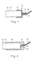
- Figure 1 shows a known protective cap 10 having a rigid first section 12 which fits over the free end of an outer casing 14 of a control cable 18.
- Cap 10 also has a rigid second section 22 with an inner diameter slightly larger than an outer diameter of an inner cable 26.
- cap 10 still has a gap 30 between the inner surface of second section 22 and the outer surface of inner cable 26, and gap 30 widens when the inner cable 26 flexes in the radial direction shown in the figure. The widened gap increases the chance that contaminants will enter the control cable.
- FIG. 2 shows another known protective cap 40 which fits over the free end of outer casing 14 of control cable 18.
- Protective cap 40 includes a generally toroidally shaped resilient seal 48 extending radially inwardly from a rigid peripheral wall 44. While this structure is ordinarily satisfactory when the inner cable extends straight from outer casing 14, a gap 50 forms when inner cable 26 flexes in the radial direction, since the position of seal 48 is fixed by the rigid wall 44. Gap 50 allows contaminants to enter the control cable.
- a protective cap for a control cable of the type having an inner cable which moves within a cable housing includes a first section sized to fit over the cable housing, and a second section sized for sealingly fitting over the inner cable.
- the second section is formed from a flexible material so that the second section can sealingly follow any bend in the inner cable.
- the cable housing may be the outer casing of the control cable, or else it may be some other structure which fits over the outer casing (such as a nose cap) or cable.
- the first section of the protective cap may have an outer diameter sized to fit within an inner portion of the cable housing.
- the protective cap system comprises an outer cap and an inner cap.
- the outer cap includes a first outer cap section and a second outer cap section, wherein the first outer cap section is sized to fit over the cable housing.
- the inner cap includes a first inner cap section sized to fit within the second outer cap section, and a second inner cap section sized for sealingly fitting over the inner cable.
- the second inner cap section is formed from a flexible material so that the second section can sealingly follow any bend in the inner cable.
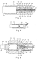
- FIG. 3 is a partial cross sectional diagram of a particular embodiment of a protective cap system 100 according to the present invention.
- Protective cap system 100 comprises an outer cap 104 and an inner cap 130.
- Outer cap 104 includes an outer cap section 108 and an outer cap section 112.
- Outer cap section 108 has an inner diameter sized to fit over a cable housing 116 which, in this embodiment, comprises the outer casing of a bicycle control cable 120.
- the free end of cable housing 116 abuts against a shoulder 122 which extends along the inner periphery of outer cap 104 at an intermediate location thereof, and the outer peripheral surfaces of outer cap section 108 and outer cap section 112 have approximately the same diameter.
- Inner cap 130 includes an inner cap section 134 and an inner cap section 138.
- Inner cap section 134 has an outer diameter sized to fit within the outer cap section 112, and inner cap section 138 has an inner diameter sized for sealingly fitting over an inner cable 140 of control cable 120.
- inner cap section 138 is in the form of a substantially constant-diameter elongated tube or sleeve having a free end 139 through which the inner cable 140 exits.
- Inner cap section 138 preferably is formed from a flexible material such as rubber. Of course, to facilitate manufacture the entire inner cap 130 may be formed as one piece from a flexible material, and in this embodiment inner cap section 134 is so constructed.
- inner cap section 134 has an outer diameter larger than an outer diameter of inner cap section 138, while the inner surface of outer cap section 112, which fully encloses the inner cap 130, has a substantially constant diameter.
- a space 144 is formed between the inner surface of outer cap section 112 and the outer surface of inner cap section 138. This allows inner cap section 138 to flex in the radial direction as shown in Figure 4 in order to follow any bend in inner cable 140.
- Inner cap section 134 has an inner surface 150 and an inner surface 154.
- both inner surface 150 and inner surface 154 have a diameter greater than an outer diameter of inner cable 140, but the diameter of inner surface 154 is greater than the diameter of inner surface 150.
- a space 155 is formed between inner surface 150 and inner cable 140, and a space 157 is formed between inner surface 154 and inner cable 140.
- An inner peripheral projection 158 having an inner diameter slightly less than the outside diameter of inner cable 140 is disposed at the transition between inner cap section 134 and inner cap section 138 for sealingly fitting over the outer surface of inner cable 140.
- Another inner peripheral projection 162 having an inner diameter slightly less than the outside diameter of inner cable 140 is disposed at the free end 139 of inner cap section 138 for sealingly fitting over the outer surface of inner cable 140.
- both inner peripheral projections 158,162 are located so that space 144 is located between the inner surface of outer cap section 112 and the inner peripheral projections 158,162.
- An inner surface 166 of inner cap section 138 has a diameter greater than the outer diameter of inner cable 140, thus forming a space 167 therebetween.
- space 167 functions as a reservoir to collect the water and prevent the water from contacting inner cable 140 or inner peripheral projection 158.
- space 157 acts as another reservoir to prevent the water from contacting inner cable 140 or proceeding toward housing 116.
- Figure 5 is a partial cross sectional diagram of an alternative embodiment of a protective cap system according to the present invention.
- the structure of the inner cap 130 is the same as in the first embodiment, so a detailed description of its structure will be omitted.
- a nose cap 200 has a nose cap section 202 and a nose cap section 210.
- Nose cap section 202 is sized to fit over an outer casing 204 of a control cable 208, and nose cap section 210 has a smaller outer diameter than nose cap section 202.
- An inner cable 214 exits through a radially expanded free end 218 of nose cap section 210.
- Nose cap section 202 is fitted within an outer cap section 222 of an outer cap 224 which, in this embodiment, is used for adjusting the position of inner cable 214 relative to outer casing 204 in a well known manner.
- a spacer cap 225 is fitted between an inner surface of outer cap section 222 and an outer surface of nose cap section 202.
- Outer cap 224 further includes an outer cap section 228 having an inner surface 232 in which is fitted inner cap section 134.
- a diameter of inner surface 232 is less than a diameter of the inner surface of outer cap section 222.
- a space 240 is formed between inner surface 232 and the outer surface of inner cap section 138.
- outer cap 224 includes an outer cap section 250 having an outer diameter less than the outer diameter of outer cap sections 222 and 228.
- An inner surface 252 of outer cap section 250 has an inner diameter slightly greater than the inner diameter of outer cap section 228, and a space 256 is formed between inner surface 252 and inner cap section 138.
- spaces 240 and 256 allow inner cap section 138 to follow any bend in cable 214, and they accommodate bulging of cap section 138 resulting from inner peripheral projections 158,162. Furthermore, since outer cap section 250 extends beyond free end 139 of inner cap section 138, outer cap section 250 helps shield inner cable 214 and inner cap 130 from contaminants, thus increasing the protective ability of the system.
- nose cap section 210 is fitted within inner cap section 134 such that expanded end 218 fits within space 157. This helps lock inner cap 130 to nose cap 200. Additionally, end 218 projects into space 157 so that space 157 completely surrounds at least part of the side surface of end 218. This structure further ensures that any water entering space 157 will be prevented from entering nose cap 200.
- the term "cable housing” may comprise the outer casing of the control cable, a nose cap such as nose cap 200 shown in Figure 5, or even cap 104 shown in Figure 3.
- the term properly describes any structure in which the inner cable moves.
- the outer caps shown may be omitted, and the inner cap may be directly fitted on the end of the outer casing ofthe control cable.
- Outer cap section 112 in the first embodiment may extend beyond the free end 139 of inner cap section 138 in a manner similar to that shown in Figure 5.
Landscapes
- Engineering & Computer Science (AREA)
- General Engineering & Computer Science (AREA)
- Mechanical Engineering (AREA)
- Health & Medical Sciences (AREA)
- Oral & Maxillofacial Surgery (AREA)
- Flexible Shafts (AREA)
- Installation Of Indoor Wiring (AREA)
Applications Claiming Priority (2)
| Application Number | Priority Date | Filing Date | Title |
|---|---|---|---|
| US631838 | 1996-04-10 | ||
| US08/631,838 US5875687A (en) | 1996-04-10 | 1996-04-10 | Protective cap system for bicycle cable |
Publications (3)
| Publication Number | Publication Date |
|---|---|
| EP0800985A2 true EP0800985A2 (de) | 1997-10-15 |
| EP0800985A3 EP0800985A3 (de) | 1999-11-03 |
| EP0800985B1 EP0800985B1 (de) | 2003-11-26 |
Family
ID=24532976
Family Applications (1)
| Application Number | Title | Priority Date | Filing Date |
|---|---|---|---|
| EP97302279A Expired - Lifetime EP0800985B1 (de) | 1996-04-10 | 1997-04-03 | Schutzkappensystem für Fahrradkabel |
Country Status (4)
| Country | Link |
|---|---|
| US (1) | US5875687A (de) |
| EP (1) | EP0800985B1 (de) |
| CN (1) | CN1077660C (de) |
| DE (1) | DE69726331T2 (de) |
Cited By (2)
| Publication number | Priority date | Publication date | Assignee | Title |
|---|---|---|---|---|
| JP2002097877A (ja) * | 2000-08-25 | 2002-04-05 | Bos Gmbh & Co Kg | 窓ブラインド |
| EP1127783A3 (de) * | 2000-02-28 | 2004-05-26 | Shimano Inc. | Kabelverbindungsvorrichtung für ein Fahrrad |
Families Citing this family (6)
| Publication number | Priority date | Publication date | Assignee | Title |
|---|---|---|---|---|
| JP2005145125A (ja) * | 2003-11-12 | 2005-06-09 | Shimano Inc | 自転車ケーブル用シール具 |
| CN101532532B (zh) * | 2008-03-11 | 2011-05-18 | 温芫鋐 | 导线保护管结构 |
| DE102016117435A1 (de) * | 2016-09-15 | 2018-03-15 | Brose Schließsysteme GmbH & Co. Kommanditgesellschaft | Bowdenzugabdichtung für Schlossmodul |
| US10501147B2 (en) * | 2017-08-22 | 2019-12-10 | Shimano Inc. | Bicycle derailleur |
| DE102022128174B4 (de) * | 2022-10-25 | 2026-02-05 | Suprajit Germany GmbH | Bowdenzug |
| JP7756062B2 (ja) * | 2022-11-11 | 2025-10-17 | ダイハツ工業株式会社 | ケーブル構造体 |
Family Cites Families (14)
| Publication number | Priority date | Publication date | Assignee | Title |
|---|---|---|---|---|
| US2845812A (en) * | 1953-01-26 | 1958-08-05 | American Motors Corp | Hand brake cable assembly |
| GB837626A (en) * | 1957-03-08 | 1960-06-15 | Dawes Cycles Ltd | Improved protective device for use with flexible transmission cables |
| GB1230359A (de) * | 1970-02-06 | 1971-04-28 | ||
| US4180346A (en) * | 1978-03-13 | 1979-12-25 | Robert L. Swanson | Coupling for telescoping members |
| US4304148A (en) * | 1979-06-22 | 1981-12-08 | Illinois Tool Works Inc. | Cable fastener assembly and method of manufacture |
| US4304149A (en) * | 1979-09-06 | 1981-12-08 | Orscheln Co. | Synthetic plastic end fitting for brake cable assemblies |
| US4534239A (en) * | 1979-09-06 | 1985-08-13 | Heimann Robert L | Brake cable fitting including scraper means |
| JPS6022206A (ja) * | 1983-07-18 | 1985-02-04 | Giichi Kuze | 読み出し専用のシ−ケンス・コントロ−ラ− |
| US4621937A (en) * | 1986-02-18 | 1986-11-11 | Maccuaig Stuart J | Self-retaining anchoring assembly and seal therefor |
| JPS6354576A (ja) * | 1986-08-21 | 1988-03-08 | 三洋電機株式会社 | 断熱箱体 |
| JPS63173512U (de) * | 1987-05-02 | 1988-11-10 | ||
| IT214880Z2 (it) * | 1988-08-01 | 1990-07-04 | Campagnolo Spa | Elemento di guida del cavo per il deragliatore posteriore di una bicicletta |
| US4963050A (en) * | 1989-03-16 | 1990-10-16 | Babcock Industries Inc. | Spring clip cable support assembly |
| US5582074A (en) * | 1995-07-20 | 1996-12-10 | Teleflex Incorporated | Park brake cable end fitting |
-
1996
- 1996-04-10 US US08/631,838 patent/US5875687A/en not_active Expired - Lifetime
-
1997
- 1997-04-03 DE DE69726331T patent/DE69726331T2/de not_active Expired - Fee Related
- 1997-04-03 EP EP97302279A patent/EP0800985B1/de not_active Expired - Lifetime
- 1997-04-10 CN CN97110542A patent/CN1077660C/zh not_active Expired - Fee Related
Cited By (3)
| Publication number | Priority date | Publication date | Assignee | Title |
|---|---|---|---|---|
| EP1127783A3 (de) * | 2000-02-28 | 2004-05-26 | Shimano Inc. | Kabelverbindungsvorrichtung für ein Fahrrad |
| JP2002097877A (ja) * | 2000-08-25 | 2002-04-05 | Bos Gmbh & Co Kg | 窓ブラインド |
| EP1182067A3 (de) * | 2000-08-25 | 2003-09-17 | BOS GmbH & Co. KG | Heckfensterrollo mit Bowdenzug |
Also Published As
| Publication number | Publication date |
|---|---|
| EP0800985B1 (de) | 2003-11-26 |
| EP0800985A3 (de) | 1999-11-03 |
| CN1077660C (zh) | 2002-01-09 |
| US5875687A (en) | 1999-03-02 |
| DE69726331T2 (de) | 2004-09-09 |
| DE69726331D1 (de) | 2004-01-08 |
| CN1167063A (zh) | 1997-12-10 |
Similar Documents
| Publication | Publication Date | Title |
|---|---|---|
| EP0727349B1 (de) | Schutzkappe für Fahrradkabel | |
| EP0713019B1 (de) | Dichtungskappe für einen Kabelanschluss | |
| US6276231B1 (en) | Grip for a bicycle shift control device | |
| EP0800985B1 (de) | Schutzkappensystem für Fahrradkabel | |
| EP1106493B2 (de) | Bremssteuervorrichtung mit Modulator | |
| US7650814B2 (en) | Bicycle cable | |
| US5674142A (en) | Control cable adjustment device | |
| IT8323884A1 (it) | Disposizione a tenuta per la protezione di un perno di guida di un freno a disco del tipo a pastiglia a pinza oscillante, per autoveicoli | |
| EP0353796B1 (de) | Dichtungsanordnung, insbesondere für einen Spielnachsteller für Schienenfahrzeuge | |
| US6042133A (en) | Index shifter for bicycle transmissions | |
| JP3504820B2 (ja) | 自転車のケーブル用保護キャップシステム | |
| US5765447A (en) | Mechanical cable system having a bellows seal | |
| JP3061547B2 (ja) | 自転車用ケーブルの防塵システム | |
| JP3061550B2 (ja) | 自転車用ケーブルの防塵カバーシステム | |
| EP0561280B1 (de) | Schnurwickelmechanismus | |
| EP0013105A1 (de) | Abschlussmanschette zur Abdichtung an konzentrisch liegenden Teilen | |
| US6360628B1 (en) | Motorcycle clutch lever cable cover | |
| GB2142698A (en) | Spot-type disc brake | |
| KR0131183Y1 (ko) | 파킹 브레이크 케이블 | |
| JP3596823B2 (ja) | 中通し竿のトップガイドおよび中通し竿 | |
| JP2003056543A (ja) | 操作ワイヤ |
Legal Events
| Date | Code | Title | Description |
|---|---|---|---|
| PUAI | Public reference made under article 153(3) epc to a published international application that has entered the european phase |
Free format text: ORIGINAL CODE: 0009012 |
|
| 17P | Request for examination filed |
Effective date: 19970423 |
|
| AK | Designated contracting states |
Kind code of ref document: A2 Designated state(s): DE FR GB IT |
|
| PUAL | Search report despatched |
Free format text: ORIGINAL CODE: 0009013 |
|
| AK | Designated contracting states |
Kind code of ref document: A3 Designated state(s): DE FR GB IT |
|
| RIC1 | Information provided on ipc code assigned before grant |
Free format text: 6B 62J 23/00 A, 6F 16C 1/26 B |
|
| 17Q | First examination report despatched |
Effective date: 20020926 |
|
| GRAH | Despatch of communication of intention to grant a patent |
Free format text: ORIGINAL CODE: EPIDOS IGRA |
|
| GRAH | Despatch of communication of intention to grant a patent |
Free format text: ORIGINAL CODE: EPIDOS IGRA |
|
| GRAS | Grant fee paid |
Free format text: ORIGINAL CODE: EPIDOSNIGR3 |
|
| GRAA | (expected) grant |
Free format text: ORIGINAL CODE: 0009210 |
|
| AK | Designated contracting states |
Kind code of ref document: B1 Designated state(s): DE FR GB IT |
|
| REG | Reference to a national code |
Ref country code: GB Ref legal event code: FG4D |
|
| REF | Corresponds to: |
Ref document number: 69726331 Country of ref document: DE Date of ref document: 20040108 Kind code of ref document: P |
|
| ET | Fr: translation filed | ||
| PLBE | No opposition filed within time limit |
Free format text: ORIGINAL CODE: 0009261 |
|
| STAA | Information on the status of an ep patent application or granted ep patent |
Free format text: STATUS: NO OPPOSITION FILED WITHIN TIME LIMIT |
|
| 26N | No opposition filed |
Effective date: 20040827 |
|
| PGFP | Annual fee paid to national office [announced via postgrant information from national office to epo] |
Ref country code: GB Payment date: 20050330 Year of fee payment: 9 |
|
| PGFP | Annual fee paid to national office [announced via postgrant information from national office to epo] |
Ref country code: FR Payment date: 20050408 Year of fee payment: 9 |
|
| PGFP | Annual fee paid to national office [announced via postgrant information from national office to epo] |
Ref country code: DE Payment date: 20060330 Year of fee payment: 10 |
|
| PG25 | Lapsed in a contracting state [announced via postgrant information from national office to epo] |
Ref country code: GB Free format text: LAPSE BECAUSE OF NON-PAYMENT OF DUE FEES Effective date: 20060403 |
|
| PGFP | Annual fee paid to national office [announced via postgrant information from national office to epo] |
Ref country code: IT Payment date: 20060430 Year of fee payment: 10 |
|
| GBPC | Gb: european patent ceased through non-payment of renewal fee |
Effective date: 20060403 |
|
| REG | Reference to a national code |
Ref country code: FR Ref legal event code: ST Effective date: 20061230 |
|
| PG25 | Lapsed in a contracting state [announced via postgrant information from national office to epo] |
Ref country code: DE Free format text: LAPSE BECAUSE OF NON-PAYMENT OF DUE FEES Effective date: 20071101 |
|
| PG25 | Lapsed in a contracting state [announced via postgrant information from national office to epo] |
Ref country code: FR Free format text: LAPSE BECAUSE OF NON-PAYMENT OF DUE FEES Effective date: 20060502 |
|
| PG25 | Lapsed in a contracting state [announced via postgrant information from national office to epo] |
Ref country code: IT Free format text: LAPSE BECAUSE OF NON-PAYMENT OF DUE FEES Effective date: 20070403 |