EP0800952B1 - Siège de véhicule, déplaçable vers l'avant pour accéder à un espace arrière - Google Patents
Siège de véhicule, déplaçable vers l'avant pour accéder à un espace arrière Download PDFInfo
- Publication number
- EP0800952B1 EP0800952B1 EP19970400778 EP97400778A EP0800952B1 EP 0800952 B1 EP0800952 B1 EP 0800952B1 EP 19970400778 EP19970400778 EP 19970400778 EP 97400778 A EP97400778 A EP 97400778A EP 0800952 B1 EP0800952 B1 EP 0800952B1
- Authority
- EP
- European Patent Office
- Prior art keywords
- lock
- shaped part
- seat
- backrest
- immobilizing
- Prior art date
- Legal status (The legal status is an assumption and is not a legal conclusion. Google has not performed a legal analysis and makes no representation as to the accuracy of the status listed.)
- Expired - Lifetime
Links
- 230000000295 complement effect Effects 0.000 claims description 3
- 230000003100 immobilizing effect Effects 0.000 claims 12
- 230000000284 resting effect Effects 0.000 claims 1
- 230000000903 blocking effect Effects 0.000 description 10
- 239000002184 metal Substances 0.000 description 7
- 229910052751 metal Inorganic materials 0.000 description 7
- 101100536354 Drosophila melanogaster tant gene Proteins 0.000 description 2
- 241000287107 Passer Species 0.000 description 1
- 229910000746 Structural steel Inorganic materials 0.000 description 1
- 238000006073 displacement reaction Methods 0.000 description 1
- 230000000694 effects Effects 0.000 description 1
- 230000014759 maintenance of location Effects 0.000 description 1
- 210000000056 organ Anatomy 0.000 description 1
Images

Classifications
-
- B—PERFORMING OPERATIONS; TRANSPORTING
- B60—VEHICLES IN GENERAL
- B60N—SEATS SPECIALLY ADAPTED FOR VEHICLES; VEHICLE PASSENGER ACCOMMODATION NOT OTHERWISE PROVIDED FOR
- B60N2/00—Seats specially adapted for vehicles; Arrangement or mounting of seats in vehicles
- B60N2/02—Seats specially adapted for vehicles; Arrangement or mounting of seats in vehicles the seat or part thereof being movable, e.g. adjustable
- B60N2/04—Seats specially adapted for vehicles; Arrangement or mounting of seats in vehicles the seat or part thereof being movable, e.g. adjustable the whole seat being movable
- B60N2/12—Seats specially adapted for vehicles; Arrangement or mounting of seats in vehicles the seat or part thereof being movable, e.g. adjustable the whole seat being movable slidable and tiltable
- B60N2/123—Seats specially adapted for vehicles; Arrangement or mounting of seats in vehicles the seat or part thereof being movable, e.g. adjustable the whole seat being movable slidable and tiltable and provided with memory locks
Definitions
- the present invention relates to the seats of vehicles, movable forward to access a space rear, in particular to access the rear seat in two-door motor vehicles.
- Such vehicle seats must be capable of on the other hand to be adjusted longitudinally, and on the other hand to be quickly moved forward to access space back then be brought back also quickly back then finding their position initially adjusted.
- the object of the present invention is in particular to overcome this drawback.
- a seat of the kind in question is characterized in that it further comprises a locking member which is mounted on a first element and which can be placed in a position blocking where it cooperates with a second element for lock the backrest in the folded position, said first and second elements one constituting the seat and the other the backrest, the blocking member being biased by a spring towards its blocking position and said blocking member being further connected to the lock by a second cable which allows the blocking member to move into its blocking position when the latch is in its unlocked position, but which, when the lock is in its locked position, places the locking member in a retracted position where it does not not block the backrest, and the lock spring being powerful enough to simultaneously bring back the lock in its locked position and the locking member in its position erased against the action of the spring of the organ of blocking, when said lock ceases to be maintained in its position unlocked by the first cable or shim.
- the seat back remains substantially in its forward folded position, which prohibits the use of the seat, as long as the lock on the slide of this seat has not returned to the locked position : this avoids any risk of accident related to a no locking of the slide.
- Figure 1 shows schematically the framework a vehicle seat 1, in particular a front seat of two-door motor vehicle, i.e. a vehicle in which it is necessary to move at least one of the front seats to access the rear seat.
- Seat 1 has a seat 2 and a backrest 3 which is pivotally mounted on the seat 2 around a transverse axis 4 horizontal, this assembly being generally carried out at by means of an articulation mechanism 5 which presents itself substantially in the form of a flattened circular housing and which is interposed between on the one hand a lateral flange 3a metallic belonging to folder 3 and on the other hand a metal side flange 2a belonging to the seat 2.
- an articulation mechanism 5 which presents itself substantially in the form of a flattened circular housing and which is interposed between on the one hand a lateral flange 3a metallic belonging to folder 3 and on the other hand a metal side flange 2a belonging to the seat 2.
- the articulation mechanism 5, which adjusts the inclination of the backrest, is a classic mechanism which does not will not be described here.
- EP-A-0 505 229 describes an example of such mechanism.
- the seat 2 is mounted on the floor 6 of the vehicle by means of two juxtaposed metal slides 7, of which only one is visible in Figure 1, so that a translation of the seat 2 in a longitudinal direction L, forward or backward.
- Each of the slides 7 comprises on the one hand a fixed metal profile 8 which is secured to the floor 6 of the vehicle, and on the other hand a movable metal profile 9 on which is mounted the seat 2 of the seat, the movable profile can slide along the fixed profile between a position front stop position and a rear stop position.
- the longitudinal adjustment of the seat 2 of the seat is produced by means of a motor electric 10.
- this motor 10 is mounted on the movable section 9 of at least one of the two slides 7, and this motor drives in rotation of a metal worm 11 via a gear 12, this worm being rotatably mounted on the movable section 9 of said slide.
- the worm 11 is screwed into a metal nut 13 which is secured to the fixed profile 8 by means a metal latch 14.
- the latch 14 is formed under the shape of one or more vertical cylindrical pins 15, two in number in the example considered, which enter corresponding vertical housings 13a formed in the lower part of the nut 13 and which slide also vertically in guide holes 16 drilled in the bottom 8a of the fixed profile.
- the two vertical pins 15 of the lock are fixed by their lower end to the same plate of horizontal link 17 which is located under the bottom 8a of the fixed profile and which is stressed upwards by a lock spring 18 mounted on a support 19 integral with the fixed profile, so that the latch 14 is normally kept in its locked position.
- this file can be provided with all means of known release allowing it to pivot freely forward.
- the articulation mechanism 5 may on the one hand have a fixed flange 5a, rigidly fixed to the flange 2a of the seat, and on the other hand a movable flange 5b having at its periphery a notch 5c or another housing in which can engage a locking hook 20 pivotally mounted on the flange 3a of the backrest.
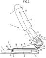
- This locking hook 20 is biased towards its position locked by a spring 21, and it is further connected by a cable 22 to a joystick 23 which is accessible on the side of the folder to allow a user to unlock the hook 20 thereby allowing pivoting forward of backrest 3, to a position folded down shown in Figure 5.
- the flange 3a of the backrest is also attached to one end of a cable metallic 24, so as to exert traction on this cable when the backrest 3 is folded down, the other end of the cable 24 being connected to an unlocking lever 25 (FIGS. 2 to 4).
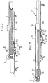
- the cable 24 slides in a flexible sheath 26 of which one end is fixed to the seat flange 2a, and of which the other end is fixed to an angle 27 secured to the fixed profile 8.
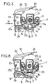
- the unlocking lever 25 is pivotally mounted on a longitudinal axis 28 integral with the support 19, and this lever present, on both sides of the axis 28, on the one hand a first arm 25a which extends to a free end fixed to the cable 24, and on the other hand a second arm 25b which extends to a free end pressing on the face upper of the connecting plate 17.
- the upward displacement of the first arm 25a of the release lever 25 loosens a wire rope 29 one end of which is attached to the free end of the first arm 25a.
- This cable 29 slides in a flexible sheath 30 of which one end is fixed to the angle iron 27 and the other end end is fixed to the flange 2a of the seat.
- the end of the cable 29 which is not fixed to the lever 25 is connected to a locking hook 31 which, when the backrest 3 is in the folded position and when the cable 29 is relaxed, engages in a notch 32 in the flange of file 3a under the action of a spring 33.
- the notch 32 is wider than the part of the hook 31 which enters said notch, so that the hook 31 blocks the backrest 3 in its folded position with a certain angular play.
- the bottom 8a of the fixed section is integral with a rod longitudinal 34 on which is mounted a slide 35 which is biased forward against the nut 13 by a spring helical 36, the slide 35 moving while remaining at immediate vicinity of the upper face of the bottom 8a of the fixed profile.
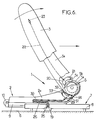
- folder 3 is then falls very slightly from its position folded down while the seat 2 slides backwards.
- the spring 18 must exert on the latch 14 enough force to overcome the force of the spring 33 urging the hook 31 towards its position blocking.
- Backrest 3 is then free to pivot towards the back, so that this folder returns to its position initial due to user action, and said file locks onto the movable flange 5b of the mechanism of articulation by means of the hook 20.
- the cables 24 and 29 described above would both be fixed to the hole 13a of the lever 13 in the device represented in FIGS. 1 to 5 of this document, or else these cables would both be fixed to the lug 103 of the lock 100 of the device shown in FIGS. 6 and 7 of this document.
Landscapes
- Engineering & Computer Science (AREA)
- Aviation & Aerospace Engineering (AREA)
- Transportation (AREA)
- Mechanical Engineering (AREA)
- Seats For Vehicles (AREA)
Description
- un verrou qui est monté sur le premier profilé et qui est déplaçable entre d'une part une position verrouillée où il coopère avec un élément complémentaire lié au deuxième profilé pour maintenir le profilé mobile dans une position normale d'utilisation réglable, et d'autre part une position déverrouillée où il permet un déplacement longitudinal libre du profilé mobile vers l'avant, jusqu'à une position de butée avant, ce verrou étant sollicité vers sa position verrouillée par un ressort de verrou et pouvant être déplacé de sa position verrouillée à sa position déverrouillée au moyen d'un premier câble relié à des moyens de commande de verrou,
- une cale qui est déplaçable entre d'une part une position active où elle bloque le verrou dans sa position déverrouillée et d'autre part une position effacée où elle n'interfère pas avec le verrou, cette cale étant sollicitée vers sa position active par un ressort de cale, et ladite cale étant maintenue dans sa position effacée tant que la glissière est dans sa position normale d'utilisation, ce maintien étant obtenu au moyen d'un organe de butée qui est monté sur le deuxième profilé de façon à être déplaçable par rapport à ce profilé pour rester au contact de la cale lorsqu'on règle la position normale d'utilisation de la glissière, et cet organe de butée restant ensuite solidaire du deuxième profilé tant qu'on ne règle pas la position normale d'utilisation de la glissière.
- les moyens d'actionnement de verrou sont constitués par le dossier lui-même, qui est relié au premier câble pour placer le verrou dans sa position déverrouillée lorsque ledit dossier est placé dans sa position rabattue, et l'organe de blocage étant conçu pour bloquer le dossier dans sa position rabattue avec un certain jeu angulaire qui permet de relever légèrement le dossier à partir de sa position rabattue, suffisamment pour que le premier câble n'empêche plus le verrou de revenir en position verrouillée ;
- au moins la glissière qui comporte le verrou est réglable longitudinalement au moyen d'un ensemble vis-écrou, cet ensemble comprenant une vis sans fin qui s'étend longitudinalement parallèlement à la glissière et qui est entraínée par un moteur, cette vis sans fin étant montée rotative sur le deuxième profilé et étant vissée dans un écrou qui constitue à la fois l'élément complémentaire avec lequel coopère le verrou et l'organe de butée qui coopère avec la cale ;
- l'organe de blocage est monté sur l'assise et peut être engagé dans un logement solidaire du dossier pour bloquer ce dossier en position rabattue ;
- le premier profilé est le profilé fixe et le deuxième profilé est le profilé mobile, et au moins le deuxième câble coulisse dans une gaine flexible qui présente deux extrémités axiales fixées rigidement l'une au profilé fixe et l'autre à l'assise du siège ;
- la cale est déplaçable axialement en translation par rapport au premier profilé, entre sa position active et sa position effacée ;
- le verrou est actionné par un levier monté pivotant autour d'un axe horizontal, ce levier présentant, de part et d'autre de son axe, un premier bras qui est relié aux premier et deuxième câbles et un deuxième bras qui coopère avec le verrou, le verrou étant monté sur le profilé fixe qui constitue ainsi le premier profilé, et ce verrou étant guidé en coulissement vertical par le profilé fixe et étant déplaçable vers le bas pour passer de sa position verrouillée à sa position déverrouillée, ce qui correspond à un déplacement vers le haut du premier bras du levier ;
- le deuxième bras du levier d'actionnement du verrou coopère avec ce verrou uniquement en prenant appui sur une portion inférieure appartenant à ce verrou, de façon à déplacer ce verrou vers le bas lorsque le premier bras du levier est déplacé vers le haut.
- la figure 1 est une vue schématique écorchée d'un siège de véhicule selon l'invention, en position normale d'utilisation,
- la figure 2 est une vue en coupe longitudinale d'une des glissières du siège de la figure 1, en position normale d'utilisation,
- la figure 3 est une vue en coupe selon la ligne III-III de la figure 2,
- la figure 4 est une vue de détail en élévation selon la direction IV de la figure 3,
- la figure 5 est une vue similaire à la figure 1, qui représente le siège lorsque le dossier est rabattu et que l'assise commence à être déplacée vers l'avant,
- la figure 6 est une vue similaire à la figure 5, qui représente le siège lorsque le dossier est rabattu et que l'assise commence a être ramenée vers l'arrière après avoir été déplacée jusqu'en butée avant,
- la figure 7 est une vue similaire à la figure 2, dans la position du siège représentée sur la figure 6,
- et la figure 8 est une vue en coupe selon la ligne VIII-VIII de la figure 7.
Claims (8)
- Siège de véhicule comportant d'une part une assise (2) montée coulissante longitudinalement vers l'avant ou vers l'arrière au moyen de glissières (7), et d'autre part un dossier (3) monté pivotant sur l'assise autour d'un axe transversal (4) horizontal de façon à pouvoir être déplacé entre une position relevée d'utilisation et une position rabattue vers l'avant où le siège n'est pas utilisable, chaque glissière (7) comportant un profilé fixe solidarisable avec le véhicule et un profilé mobile qui supporte l'assise, l'un de ces deux profilés étant dit ci-après premier profilé (8) et l'autre profilé étant dit ci-après deuxième profilé (9), au moins une des glissières comportant :siège caractérisé en ce qu'il comporte en outre un organe de blocage (31) qui est monté sur un premier élément (2) et qui peut être placé dans une position de blocage où il coopère avec un deuxième élément (3) pour bloquer le dossier en position rabattue, lesdits premier et deuxième éléments constituant l'un l'assise (2) et l'autre le dossier (3), l'organe de blocage (31) étant sollicité par un ressort (33) vers sa position de blocage et ledit organe de blocage étant en outre relié au verrou (14) par un deuxième câble (29) qui permet à l'organe de blocage de se placer dans sa position de blocage lorsque le verrou est dans sa position déverrouillée, mais qui, lorsque le verrou est dans sa position verrouillée, place l'organe de blocage dans une position effacée où il ne bloque pas le dossier, et le ressort de verrou (18) étant suffisamment puissant pour ramener simultanément le verrou (14) dans sa position verrouillée et l'organe de blocage (31) dans sa position effacée contre l'action du ressort (33) de l'organe de blocage, lorsque ledit verrou (14) cesse d'être maintenu dans sa position déverrouillée par le premier câble (24) ou la cale (35).un verrou (14) qui est monté sur le premier profilé (8) et qui est déplaçable entre d'une part une position verrouillée où il coopère avec un élément complémentaire (13) lié au deuxième profilé, pour maintenir le profilé mobile dans une position normale d'utilisation réglable, et d'autre part une position déverrouillée où il permet un déplacement longitudinal libre du profilé mobile (9) vers l'avant, jusqu'à une position de butée avant, ce verrou (14) étant sollicité vers sa position verrouillée par un ressort de verrou (18) et pouvant être déplacé de sa position verrouillée à sa position déverrouillée au moyen d'un premier câble relié à des moyens d'actionnement de verrou,et une cale (35) qui est déplaçable entre d'une part une position active où elle bloque le verrou (14) dans sa position déverrouillée et d'autre part une position effacée où elle n'interfère pas avec le verrou, cette cale étant sollicitée vers sa position active par un ressort de cale (36), et ladite cale étant maintenue dans sa position effacée tant que la glissière est dans sa position normale d'utilisation, ce maintien étant obtenu au moyen d'un organe de butée (13) qui est monté sur le deuxième profilé de façon à être déplaçable par rapport à ce profilé pour rester au contact de la cale lorsqu'on règle la position normale d'utilisation de la glissière, cet organe de butée restant ensuite solidaire du deuxième profilé tant qu'on ne règle pas la position normale d'utilisation de la glissière,
- Siège de véhicule selon la revendication 1, dans lequel les moyens d'actionnement de verrou sont constitués par le dossier (3) lui-même, qui est relié au premier câble (24) pour placer le verrou (14) dans sa position déverrouillée lorsque ledit dossier est placé dans sa position rabattue, et l'organe de blocage (31) étant conçu pour bloquer le dossier (3) dans sa position rabattue avec un certain jeu angulaire qui permet de relever légèrement le dossier (3) à partir de sa position rabattue, suffisamment pour que le premier câble (24) n'empêche plus le verrou (14) de revenir en position verrouillée.
- Siège de véhicule selon la revendication 1 ou la revendication 2, dans lequel au moins la glissière (7) qui comporte le verrou (14) est réglable longitudinalement au moyen d'un ensemble vis-écrou (11, 13), cet ensemble comprenant une vis sans fin (11) qui s'étend longitudinalement parallèlement à la glissière et qui est entraínée par un moteur (10), cette vis sans fin étant montée rotative sur le deuxième profilé (9) et étant vissée dans un écrou (13) qui constitue à la fois l'élément complémentaire avec lequel coopère le verrou (14) et l'organe de butée qui coopère avec la cale (35).
- Siège selon l'une quelconque des revendications précédentes, dans lequel l'organe de blocage (31) est monté sur l'assise (2) et peut être engagé dans un logement (32) solidaire du dossier (3) pour bloquer ce dossier en position rabattue.
- Siège selon la revendication 4, dans lequel le premier profilé (8) est le profilé fixe et le deuxième profilé (9) est le profilé mobile, et dans lequel au moins le deuxième câble (29) coulisse dans une gaine (30) flexible qui présente deux extrémités axiales fixées rigidement l'une au profilé fixe (8) et l'autre à l'assise (2) du siège.
- Siège selon l'une quelconque des revendications précédentes, dans lequel la cale (35) est déplaçable axialement en translation par rapport au premier profilé (8), entre sa position active et sa position effacée.
- Siège selon l'une quelconque des revendications précédentes, dans lequel le verrou (14) est actionné par un levier (25) monté pivotant autour d'un axe horizontal (28), ce levier présentant, de part et d'autre de son axe, un premier bras (25a) qui est relié aux premier et deuxième câbles (24, 29) et un deuxième bras qui coopère avec le verrou (14), le verrou étant monté sur le profilé fixe (8) qui constitue ainsi le premier profilé, et ce verrou étant guidé en coulissement vertical par le profilé fixe et étant déplaçable vers le bas pour passer de sa position verrouillée à sa position déverrouillée, ce qui correspond à un déplacement vers le haut du premier bras (25a) du levier.
- Siège selon la revendication 7, dans lequel le deuxième bras (25b) du levier d'actionnement du verrou coopère avec ce verrou (14) uniquement en prenant appui sur une portion inférieure (17) appartenant à ce verrou, de façon à déplacer ledit verrou vers le bas lorsque le premier bras (25a) du levier est déplacé vers le haut.
Applications Claiming Priority (2)
| Application Number | Priority Date | Filing Date | Title |
|---|---|---|---|
| FR9604347A FR2747079B1 (fr) | 1996-04-05 | 1996-04-05 | Siege de vehicule, deplacable vers l'avant pour acceder a un espace arriere |
| FR9604347 | 1996-04-05 |
Publications (2)
| Publication Number | Publication Date |
|---|---|
| EP0800952A1 EP0800952A1 (fr) | 1997-10-15 |
| EP0800952B1 true EP0800952B1 (fr) | 1999-09-29 |
Family
ID=9490984
Family Applications (1)
| Application Number | Title | Priority Date | Filing Date |
|---|---|---|---|
| EP19970400778 Expired - Lifetime EP0800952B1 (fr) | 1996-04-05 | 1997-04-03 | Siège de véhicule, déplaçable vers l'avant pour accéder à un espace arrière |
Country Status (3)
| Country | Link |
|---|---|
| EP (1) | EP0800952B1 (fr) |
| DE (1) | DE69700556T2 (fr) |
| FR (1) | FR2747079B1 (fr) |
Cited By (2)
| Publication number | Priority date | Publication date | Assignee | Title |
|---|---|---|---|---|
| US8408630B2 (en) | 2009-08-21 | 2013-04-02 | Toyota Boshoku Kabushiki Kaisha | Vehicle seat reclining apparatus |
| DE102013221924A1 (de) * | 2013-09-27 | 2015-04-23 | Johnson Controls Components Gmbh & Co. Kg | Fahrzeugsitz mit einem Beschlag mit Easy-Entry-Funktion |
Families Citing this family (15)
| Publication number | Priority date | Publication date | Assignee | Title |
|---|---|---|---|---|
| FR2769878B1 (fr) * | 1997-10-22 | 1999-12-31 | Faure Bertrand Equipements Sa | Mecanisme de blocage de securite destine a etre utilise dans un siege coulissant de vehicule |
| FR2795689B1 (fr) | 1999-07-02 | 2001-10-05 | Faure Bertrand Equipements Sa | Dispositif de verrouillage pour siege de vehicule, et siege comportant un tel dispositif |
| DE19957201A1 (de) * | 1999-11-27 | 2001-06-07 | Giok Djien Go | Längsverstellmechanismus mit Hilfsmitteln zur Minimierung der Sitzbauteile, Montagezeit, Herstellungskosten und Beanspruchung |
| DE10057723A1 (de) * | 2000-11-15 | 2002-05-29 | Brose Fahrzeugteile | Fahrzeugsitz |
| DE10057724B4 (de) * | 2000-11-15 | 2010-01-28 | Brose Fahrzeugteile Gmbh & Co. Kommanditgesellschaft, Coburg | Kraftfahrzeugsitz |
| DE10127067A1 (de) | 2001-05-23 | 2002-11-28 | Brose Fahrzeugteile | Kraftfahrzeugsitz |
| DE10127153A1 (de) * | 2001-05-25 | 2002-11-28 | Brose Fahrzeugteile | Kraftfahrzeugsitz |
| DE10152556C1 (de) * | 2001-10-24 | 2002-10-17 | Faurecia Autositze Gmbh & Co | Kraftfahrzeugsitz mit klappbarer Rückenlehne |
| DE20214611U1 (de) | 2002-09-13 | 2002-11-21 | Brose Fahrzeugteile GmbH & Co. KG, Coburg, 96450 Coburg | Kraftfahrzeugsitz |
| DE10340229B4 (de) * | 2003-08-28 | 2015-10-15 | Volkswagen Ag | Sicherheitseinrichtung zur Verriegelung einer Sitzlängsverschiebung |
| DE202005006901U1 (de) | 2005-04-22 | 2006-08-24 | Brose Fahrzeugteile Gmbh & Co. Kommanditgesellschaft, Coburg | Kraftfahrzeugsitzanordnung |
| JP5594092B2 (ja) | 2010-11-29 | 2014-09-24 | トヨタ紡織株式会社 | 車両用シート |
| JP5591664B2 (ja) | 2010-11-29 | 2014-09-17 | トヨタ紡織株式会社 | 車両用シート |
| US9415705B2 (en) | 2014-05-01 | 2016-08-16 | AISIN Technical Center of America, Inc. | Power seat with complete manual walk-in system |
| CN120918501A (zh) * | 2025-08-29 | 2025-11-11 | 康辉医疗科技(苏州)有限公司 | 基于侧向进出且便于就座和坐姿调节的助浴方法 |
Family Cites Families (2)
| Publication number | Priority date | Publication date | Assignee | Title |
|---|---|---|---|---|
| JPS52105428A (en) * | 1976-02-27 | 1977-09-03 | Nissan Motor Co Ltd | Memory including seat for walk-in rail |
| DE19509344C2 (de) * | 1995-03-15 | 1998-04-23 | Keiper Recaro Gmbh Co | Fahrzeugsitz |
-
1996
- 1996-04-05 FR FR9604347A patent/FR2747079B1/fr not_active Expired - Lifetime
-
1997
- 1997-04-03 EP EP19970400778 patent/EP0800952B1/fr not_active Expired - Lifetime
- 1997-04-03 DE DE1997600556 patent/DE69700556T2/de not_active Expired - Fee Related
Cited By (3)
| Publication number | Priority date | Publication date | Assignee | Title |
|---|---|---|---|---|
| US8408630B2 (en) | 2009-08-21 | 2013-04-02 | Toyota Boshoku Kabushiki Kaisha | Vehicle seat reclining apparatus |
| DE102010039553B4 (de) * | 2009-08-21 | 2014-05-15 | Aisin Seiki Kabushiki Kaisha | Fahrzeugsitz-Neigevorrichtung |
| DE102013221924A1 (de) * | 2013-09-27 | 2015-04-23 | Johnson Controls Components Gmbh & Co. Kg | Fahrzeugsitz mit einem Beschlag mit Easy-Entry-Funktion |
Also Published As
| Publication number | Publication date |
|---|---|
| FR2747079B1 (fr) | 1998-06-12 |
| DE69700556T2 (de) | 2000-05-04 |
| FR2747079A1 (fr) | 1997-10-10 |
| DE69700556D1 (de) | 1999-11-04 |
| EP0800952A1 (fr) | 1997-10-15 |
Similar Documents
| Publication | Publication Date | Title |
|---|---|---|
| EP0798154B1 (fr) | Glissière pour siège de véhicule, et siège comportant une telle glissière | |
| FR2760416A1 (fr) | Siege de vehicule comportant un appui-tete rabattable, et vehicule comportant un tel siege | |
| EP0800952A1 (fr) | Siège de véhicule, déplaçable vers l'avant pour accéder à un espace arrière | |
| FR3071447A1 (fr) | Siege a basculement automatique | |
| FR2821028A1 (fr) | Dispositif d'assise comportant un dossier rabattable | |
| FR2820696A1 (fr) | Siege de vehicule dote d'un dossier rabattable | |
| FR2700735A1 (fr) | Siège de véhicule enlevable et réglable en position. | |
| FR3116771A1 (fr) | Siège de véhicule à assise et dossiers inclinables pour faciliter l’accès aux places arrière | |
| FR2890912A1 (fr) | Siege de vehicule. | |
| FR2756522A1 (fr) | Glissiere pour siege de vehicule et siege comportant une telle glissiere | |
| EP0537057B1 (fr) | Glissière pour siège de véhicule à position de retour fixe | |
| FR3083174A1 (fr) | Siege de vehicule automobile | |
| FR2524285A1 (fr) | Siege transformable, notamment de vehicule automobile | |
| FR2748432A1 (fr) | Dispositif d'assise pour vehicule automobile, comportant un appui-tete pivotant escamotable | |
| FR2770811A1 (fr) | Siege de vehicule dote d'une assise basculable vers l'avant, et vehicule comportant un tel siege | |
| FR3034723A1 (fr) | Dispositif de verrouillage de banquette arriere | |
| EP0373081B1 (fr) | Siège escamotable notamment pour équipement de véhicules automobiles | |
| EP0402195B1 (fr) | Dispositif d'arrimage démontable d'une banquette arrière pour véhicule automobile | |
| FR2920012A1 (fr) | Siege reglable et escamotable dans deux positions ainsi que son procede d'escamotage | |
| EP1808330A2 (fr) | Siège pour véhicule automobile mobile selon un premier axe x et un second axe y et véhicule automobile comprenant un tel siège | |
| EP0965478A1 (fr) | Siège arrière réglable en position longitudinale dans un habitacle de véhicule automobile | |
| FR2796897A1 (fr) | Siege de vehicule automobile deverrouillable dote d'un dossier rabattable, et vehicule comportant un tel siege | |
| EP1215078B1 (fr) | Strapontin intérieur pour véhicule automobile | |
| EP1632391B1 (fr) | Siège pour un véhicule automobile et notamment siège arrière | |
| FR2766430A1 (fr) | Siege ergonomique pour vehicule |
Legal Events
| Date | Code | Title | Description |
|---|---|---|---|
| PUAI | Public reference made under article 153(3) epc to a published international application that has entered the european phase |
Free format text: ORIGINAL CODE: 0009012 |
|
| AK | Designated contracting states |
Kind code of ref document: A1 Designated state(s): DE ES GB IT |
|
| 17P | Request for examination filed |
Effective date: 19971204 |
|
| GRAG | Despatch of communication of intention to grant |
Free format text: ORIGINAL CODE: EPIDOS AGRA |
|
| GRAG | Despatch of communication of intention to grant |
Free format text: ORIGINAL CODE: EPIDOS AGRA |
|
| GRAH | Despatch of communication of intention to grant a patent |
Free format text: ORIGINAL CODE: EPIDOS IGRA |
|
| 17Q | First examination report despatched |
Effective date: 19990223 |
|
| GRAH | Despatch of communication of intention to grant a patent |
Free format text: ORIGINAL CODE: EPIDOS IGRA |
|
| GRAA | (expected) grant |
Free format text: ORIGINAL CODE: 0009210 |
|
| AK | Designated contracting states |
Kind code of ref document: B1 Designated state(s): DE ES GB IT |
|
| PG25 | Lapsed in a contracting state [announced via postgrant information from national office to epo] |
Ref country code: IT Free format text: LAPSE BECAUSE OF FAILURE TO SUBMIT A TRANSLATION OF THE DESCRIPTION OR TO PAY THE FEE WITHIN THE PRE;WARNING: LAPSES OF ITALIAN PATENTS WITH EFFECTIVE DATE BEFORE 2007 MAY HAVE OCCURRED AT ANY TIME BEFORE 2007. THE CORRECT EFFECTIVE DATE MAY BE DIFFERENT FROM THE ONE RECORDED.SCRIBED TIME-LIMIT Effective date: 19990929 Ref country code: GB Free format text: LAPSE BECAUSE OF FAILURE TO SUBMIT A TRANSLATION OF THE DESCRIPTION OR TO PAY THE FEE WITHIN THE PRESCRIBED TIME-LIMIT Effective date: 19990929 Ref country code: ES Free format text: THE PATENT HAS BEEN ANNULLED BY A DECISION OF A NATIONAL AUTHORITY Effective date: 19990929 |
|
| REF | Corresponds to: |
Ref document number: 69700556 Country of ref document: DE Date of ref document: 19991104 |
|
| GBV | Gb: ep patent (uk) treated as always having been void in accordance with gb section 77(7)/1977 [no translation filed] |
Effective date: 19990929 |
|
| PGFP | Annual fee paid to national office [announced via postgrant information from national office to epo] |
Ref country code: DE Payment date: 20000330 Year of fee payment: 4 |
|
| PLBE | No opposition filed within time limit |
Free format text: ORIGINAL CODE: 0009261 |
|
| STAA | Information on the status of an ep patent application or granted ep patent |
Free format text: STATUS: NO OPPOSITION FILED WITHIN TIME LIMIT |
|
| 26N | No opposition filed | ||
| PG25 | Lapsed in a contracting state [announced via postgrant information from national office to epo] |
Ref country code: DE Free format text: LAPSE BECAUSE OF NON-PAYMENT OF DUE FEES Effective date: 20020201 |