EP0800100A1 - Muffenanordnung zum Einführen eines Führungszapfen ohne Spiel - Google Patents
Muffenanordnung zum Einführen eines Führungszapfen ohne Spiel Download PDFInfo
- Publication number
- EP0800100A1 EP0800100A1 EP97105114A EP97105114A EP0800100A1 EP 0800100 A1 EP0800100 A1 EP 0800100A1 EP 97105114 A EP97105114 A EP 97105114A EP 97105114 A EP97105114 A EP 97105114A EP 0800100 A1 EP0800100 A1 EP 0800100A1
- Authority
- EP
- European Patent Office
- Prior art keywords
- guide pin
- pin
- ferrule
- clamp
- predetermined
- Prior art date
- Legal status (The legal status is an assumption and is not a legal conclusion. Google has not performed a legal analysis and makes no representation as to the accuracy of the status listed.)
- Withdrawn
Links
Images


Classifications
-
- G—PHYSICS
- G02—OPTICS
- G02B—OPTICAL ELEMENTS, SYSTEMS OR APPARATUS
- G02B6/00—Light guides; Structural details of arrangements comprising light guides and other optical elements, e.g. couplings
- G02B6/24—Coupling light guides
- G02B6/36—Mechanical coupling means
- G02B6/38—Mechanical coupling means having fibre to fibre mating means
- G02B6/3807—Dismountable connectors, i.e. comprising plugs
- G02B6/3873—Connectors using guide surfaces for aligning ferrule ends, e.g. tubes, sleeves, V-grooves, rods, pins, balls
- G02B6/3882—Connectors using guide surfaces for aligning ferrule ends, e.g. tubes, sleeves, V-grooves, rods, pins, balls using rods, pins or balls to align a pair of ferrule ends
-
- G—PHYSICS
- G02—OPTICS
- G02B—OPTICAL ELEMENTS, SYSTEMS OR APPARATUS
- G02B6/00—Light guides; Structural details of arrangements comprising light guides and other optical elements, e.g. couplings
- G02B6/24—Coupling light guides
- G02B6/36—Mechanical coupling means
- G02B6/38—Mechanical coupling means having fibre to fibre mating means
- G02B6/3807—Dismountable connectors, i.e. comprising plugs
- G02B6/3873—Connectors using guide surfaces for aligning ferrule ends, e.g. tubes, sleeves, V-grooves, rods, pins, balls
- G02B6/3885—Multicore or multichannel optical connectors, i.e. one single ferrule containing more than one fibre, e.g. ribbon type
Definitions
- the present invention relates generally to guide pin retention mechanisms and, more particularly, to a ferrule assembly which positively engages an associated guide pin.
- optical fiber communications continues to increase due, at least in part, to the increased bandwidth, quality and reliability of optical fiber transmission.
- optical fibers not just as trunk and distribution lines along which signals are transmitted relatively long distances within a communications system, but also directly to the home, such as in a Fiber To The Home (FTTH) system.
- FTTH Fiber To The Home
- fiber optic connectors In order to provide this alignment, fiber optic connectors have been developed which align either a pair or more of optical fibers to allow for efficient transmission of light or other optical signals along a predetermined transmission line or path and to provide the flexibility to route the line in or to a variety of termination points and distances.
- fiber optic connectors provide for the reliable transmission of optical signals to the desired termination point while maintaining at least a minimum operating level of optical signal strength.
- optical fiber optic cables which group or contain a plurality of individual optical fibers, such as with an integrated multi-fiber optic ribbon connector.
- the fiber optic ribbon products which are available today are increasingly smaller, approaching the size of a strand of hair, and typically include a plurality of optical fibers such as 4, 8 or 12 optical fibers.
- the optical fibers of a fiber optic ribbon cable are typically disposed in a side by side or "ribbon" pattern and are generally individually encapsulated so as to optically isolate the optical fibers from the environment and from each other. Accordingly, the multi-fiber connectors employed to interconnect these fiber ribbons are relatively small and demand tight dimensional tolerances to insure that the proper alignment is maintained between the corresponding optical fibers.
- the outwardly extending portions of the guide pins can be inserted within respective apertures defined by a second fiber optic connector such that the first and second fiber optic connectors and, as a result, the respective fibers are maintained in a predetermined aligned relationship.
- a multi-fiber connector can include a guide pin holding member for frictionally retaining the guide pins within the connector by providing an interference or "press" fit between the guide pin holding member and the associated guide pin.
- the guide pin holding member defines a bore for receiving the guide pin which has cross sectional area which is smaller than the guide pin. The guide pin is then pressed into the smaller bore and retained by the resulting frictional forces. Due to the reliance upon frictional engagement, however, the resulting retention force with which the guide pin is held can be relatively low, such as about 1 lb. in some instances.
- the relatively low retention force provided by the guide pin holding member may still allow the guide pin to become displaced during the disconnection and subsequent reconnection of the multi-fiber connector.
- the guide pin Due to the positive engagement of the pin clamp with the guide pin and, in one advantageous embodiment, with the recessed portion of the guide pin, the guide pin is securely retained by the ferrule assembly, such as during subsequent connection and disconnection of a multi-fiber connector which incorporates the ferrule assembly of the present invention.
- the guide pin will not become displaced, but will, instead, remain in position within the ferrule assembly, such as during the subsequent connection and disconnection of a multi-fiber connector incorporating the ferrule assembly.
- the pin clamp is disposed in a predetermined position relative to the ferrule such that the guide pin engaged by the pin clamp extends through the respective guide pin opening and outwardly from the front face of the ferrule.
- the guide pin includes a number of circumferentially extending grooves which are spaced lengthwise along the guide pin.
- the ferrule defines at least one window which opens into a respective guide pin opening to thereby expose a portion of the guide pin disposed within the respective guide pin opening.
- the engagement portion of the pin clamp engages the portion of the guide pin exposed within the window.
- the guide pin of this embodiment includes a recessed portion which is exposed within the window and is positively engaged by the engagement portion of the pin clamp.
- the pin clamp can define an internal cavity adjacent to the engagement portion for receiving the enlarged portion of a guide pin while the engagement portion extends at least partially within the recessed portion of the guide pin.
- the pin clamp defines an opening through which the enlarged portion of the guide pin can be inserted.
- the engagement portion of the pin clamp of this embodiment includes a plurality of deflectable tabs which border the opening defined by the pin clamp while the deflectable tabs permit the enlarged portion of the guide pin to be inserted through the opening, the deflectable tabs securely engage and seat within the recessed portion of the guide pin, thereby securing the guide pin within the pin clamp.
- the ferrule assembly includes a pin clamp for securely engaging the guide pin such that the guide pin does not become displaced, such as during subsequent connection and disconnection of a multi-fiber connector which incorporates the ferrule assembly.
- the guide pin of one embodiment of the present invention defines a recessed portion, such a groove, which can be positively engaged by the pin clamp so as to significantly increase the retention force with which the guide pin is held within the resulting ferrule assembly in comparison with a conventional guide pin holding member which relies solely upon frictional engagement with the guide pin.
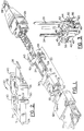
- Figure 1 is an exploded perspective view of a multi-fiber connector which includes a ferrule assembly according to one embodiment of the present invention.
- Figure 5 is an end view of the embodiment of the pin clamp illustrated in Figure 3.
- Figure 6 is a cross-sectional view of a portion of the pin clamp illustrated in Figure 3 taken along line 6-6 of Figure 4.
- Figure 7 is a perspective view of a guide pin according to one embodiment of the present invention.
- Figure 8 is a fragmentary top view of a ferrule assembly according to one embodiment of the present invention illustrating the positive engagement of the guide pins by the pin clamp and the insertion of the guide pins within respective guide pin openings defined by the ferrule according to one embodiment of the present invention.
- Figure 9 is a perspective view of a guide pin according to another embodiment of the present invention.
- Figure 10 is a perspective view of a guide pin according to yet another embodiment of the present invention.
- Figure 11 is an exploded perspective view of a ferrule assembly according to another embodiment of the present invention.
- Figure 12 is a perspective view of the ferrule assembly illustrated by Figure 11 following assembly thereof.
- Figure 13 is a cross-sectional view of the ferrule assembly of Figures 11 and 12 taken along line 13-13 of Figure 12.
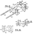
- Figure 16 is a bottom view of the embodiment of the pin clamp of the present invention shown in Figure 14.
- the ferrule assembly 20 of the present invention is illustrated and described herein in conjunction with a multi-fiber connector.
- the ferrule assembly of the present invention can also be incorporated within a single fiber connector without departing from the spirit and scope of the present invention.
- the ferrule assembly of the present invention can be readily employed in applications which do not include a fiber optic connector.
- the ferrule assembly of the present invention can align one or more optical fibers within an optoelectronic module or within a passive optical device, such as a coupler, without departing from the spirit and scope of the present invention.
- the guide pins 24 which extend outwardly from the front face of the ferrule assembly 20 of the present invention are adapted to be inserted into corresponding guide pin openings which are defined by another fiber optic connector such that a pair of fiber optic connectors and, in turn, the optical fibers of each of the fiber optic connectors are aligned in a predetermined manner.
- a fiber optic connector can also include springs and other alignment mechanisms to insure that the respective fiber optic connectors are spaced in a tightly abutting manner to minimize signal leakage between the aligned fiber optic connectors.
- the fiber optic connector includes the ferrule assembly 20 of the present invention.
- the ferrule assembly includes a ferrule 30 , a pin clamp 40 , and a plurality of lengthwise extending guide pins 24 .
- the ferrule is preferably made out of a molded plastic material and, in one embodiment, includes a mixture of about 20% phenylic resin by weight and 80% aggregate filler, such as silica, by weight.
- the ferrule is configured to provide a plurality of guide pin openings 22 as well as at least one fiber optic opening 26 , each opening extending between the opposed front and rear faces 31 , 32 .
- the guide pins typically extend through respective ones of the guide pin openings and outwardly from the front face 31 of the ferrule as shown in Figure 2.
- a plurality of optical fibers are also inserted through the ferrule 30 generally at an earlier point in the assembly process than the insertion of the guide pins 24 as known by those skilled in the art.
- the fibers are positioned and engaged (such as by epoxy or glue) at least partially within respective ones of the fiber optic openings 26 defined by the ferrule 30 such that end portions of the optical fibers are exposed through the front face 31 of the ferrule.
- the fiber optic ribbon is typically truncated at the front face of the connector to provide the necessary optical communication with a mating connector.
- the truncated fibers can also be processed to provide the necessary definition of the individual optical fibers at the front face of the connector.
- This additional processing can include high precision machining and polishing or etching with a slurry or the like so as to expose highly polished fibers in respective openings defined in the front face of the ferrule.
- a predetermined length of fiber optic ribbon also extends from the rear face 32 of the ferrule.
- the ferrule assembly 20 of the present invention also includes at least one guide pin 24 .
- the various embodiments of the guide pin each include an enlarged portion 80 having first predetermined dimensions in lateral cross-section and at least one recessed portion 82 having second predetermined dimensions, less than the first predetermined dimensions, in lateral cross-section.
- the enlarged portion is disposed at one end of the guide pin and the recessed portion is disposed along a medal segment of the guide pin.
- the enlarged portion of the guide pin is larger than the recessed portion of the guide pin, the enlarged portion of one advantageous embodiment of the guide pin has the same general dimensions, in lateral cross-section, as the body or shaft of the guide pin as shown in Figure 7.
- the pin clamp 40 retains and positively engages a portion of the guide pin 24 .
- the pin clamp includes an engagement portion 44 which provides positive retention forces which, in one advantageous embodiment, are about 6 to about 12 times greater than the retention forces provided by conventionally retained assemblies.
- the engagement portion 44 includes a pair of opposed arms 45 which define a slot 50 therebetween.
- the slot includes an enlarged interior portion sized to receive the enlarged portion 80 of a guide pin 24 .
- the slot also opens through the front face 52 of the pin clamp so as to define a gap having a predetermined width which smaller than the lateral cross-sectional dimensions of the enlarged portion of a guide pin.
- the slot also opens through the sidewalls 56 of the pin clamp so as to receive an end portion of a guide pin during the assembly of the ferrule assembly 20 as described below.
- one end of a guide pin 24 is inserted into the slot 50 such that the enlarged portion 80 of the guide pin is locked into the slot by the engagement portion 44 of the pin clamp in a manner which positively engages the guide pin and prevents the guide pin from dislodging or moving in the axial direction.
- the guide pin extends outwardly (axially) from the front face 52 of the pin clamp as shown in Figure 3.
- the slot 50 opens through at least part of a sidewall 56 and at least part of a front surface 52 of the pin clamp.
- the slot extends across the entire front surface and a portion of the sidewall.
- a portion of the slot is preferably defined by the opposed arms 45 of the engagement portion 44 which are configured to adaptably receive and lock into the recessed portion 82 of a guide pin 24 .
- a guide pin 24 can be inserted through an entry point which is typically defined by the portion of the slot 50 which opens through a sidewall 56 of the pin clamp.
- the guide pin can then be slidably moved in a transverse direction through the slot until the engagement portion 44 attaches and locks into the recessed portion 82 of the guide pin so as to positively retain and engage the guide pin within the slot.
- the one end of the guide pin 24 is preferably inserted in the slot 50 at the innermost portion 59 of the slot and is slidably moved in a transverse direction outward towards the outermost portion 57 until the guide pin is engaged and locked into position.
- the slot is preferably configured to allow one end of the guide pin to be inserted into the slot at an entry point.
- the entry slot can also be positioned at the top, bottom or one of the sides perpendicular to the axial direction, if so desired.
- the enlarged portion of the slot 50 includes an internal cavity 48 adjacent the engagement portion 44 which receives the enlarged portion 80 of the guide pin 24 to prevent the guide pin from being advanced further through the pin clamp.
- the internal cavity is adjacent the engagement portion such that the opposed arms 45 of the engagement portion of the pin clamp can engage the recessed portion 82 of the guide pin while the enlarged portion of the guide pin is held within the internal cavity, thereby further securing the guide pin within the pin clamp.
- the pin clamp 40 of this embodiment is preferably configured to securely retain a pair of guide pins 24 .
- the pin clamp of this embodiment can include a pair of spanning arms 49 which define an open center cavity 51 through which the fiber ribbon 28 extends.
- the pin clamp of this embodiment also includes a bridge portion 46 extending across the open center cavity and connecting the pair of spanning arms.
- the pin clamp is preferably a molded component and, in one embodiment, is produced from a polyester thermoplastic material such as polybutylene terephthalate.
- the slot 50 defined by the engagement portion 44 of the pin clamp 40 opens through the front face of the pin clamp to define a gap of a predetermined width, such as about 0.375 mm in one embodiment.
- the corresponding guide pin 24 of this exemplary embodiment has a recessed portion 82 having second predetermined dimensions in lateral cross-section which are either smaller than the width of the gap.
- the guide pin can have a recessed portion having second predetermined dimensions in lateral cross-section which are slightly larger, such as about 5% to about 10% larger, than the width of the gap such that the opposed arm 45 of the engagement portion 44 can frictionally engage the recessed portion of the guide pin.
- the corresponding guide pin of this exemplary embodiment has an enlarged portion 80 having first predetermined dimensions in lateral cross-section which are greater than the width of the gap such that the enlarged portion of the guide pin is locked within the pin clamp.
- the corresponding guide pin can be generally cylindrical in shape such that the recessed portion has a diameter of about 0.39 mm to about 0.4 mm and the enlarged portion has a diameter of about 0.69 mm to about 0.7 mm.
- the guide pin 24 of the present is preferably designed such that the ratio of the predetermined diameter of the recessed portion 82 to the predetermined diameter of the enlarged portion 80 is between about 0.40 and about 0.75.
- the guide pin should have sufficient mechanical strength to withstand the anticipated load placed on the guide pin during service, while providing a recessed portion which is significantly smaller in lateral cross-section than the enlarged portion such that the engagement portion 44 of the pin clamp 40 can positively engage the recessed portion, thereby securing the guide pin within the ferrule assembly. While particular dimensions of an exemplary guide pin are provided above, these dimensions are merely for purposes of explanation and the guide pin and corresponding pin clamp can have a variety of sizes without departing from the spirit and scope of the present invention.
- FIG. 11-13 An alternative embodiment of a pin clamp 40' having a pair of engagement portions 44' for positively engaging respective ones of a pair of guide pins 24 is illustrated in Figures 11-13.
- the pin clamp of this embodiment is not limited to a pair of engagement portions and may include a plurality of engagement portions, or even a single engagement portion.
- the pin clamp 40' of Figures 11-13 will be described as an alternative to the pin clamp 40 of Figures 1-6, it is also anticipated that the pin clamp 40' can be used in conjunction with the above described embodiment of a pin clamp 40 to thereby further increase the positive retention force with which the guide pin(s) are held.
- the engagement portion 44' of this embodiment of the pin clamp 40' also comprises a pair of opposed arms 45' which define a gap of a predetermined width therebetween.
- the gap width is less than the first predetermined dimensions (in lateral cross-section) of the enlarged portion 80 of the respective guide pin 24 .
- the gap is sized to snugly receive the recessed portion 82 of the guide pin, but is smaller than the enlarged portion of the guide pin to restrict any axial movement of the guide pin, thereby precluding the enlarged portion of the guide pin from axially moving through the smaller gap.
- the pin clamp of this embodiment also provides a positive retention force so as to restrict, if not eliminate, axial movement of the guide pin.
- the ferrule 30 of this embodiment can be configured to further define at least one window 33 which opens into a guide pin opening 22 .
- a guide pin 24 can then be inserted either from a front or rear face 31 , 32 of the ferrule so as to extend through the respective guide pin opening.
- the guide pin and, more preferably, the recessed portion 82 of the guide pin is externally exposed by the window defined in the ferrule.
- the pin clamp 40' and, more particularly, the engagement portion 44' of the pin clamp is configured to extend through the window and to fit over and around a suitably configured guide pin, thereby positively engaging the guide pin as shown in cross-section in Figure 13.
- the pin clamp 40' of this embodiment can be easily assembled to the ferrule by inserting the engagement portion through the window defined by the ferrule to extend over and around a guide pin and, more preferably, to engage a notched or grooved or recessed portion of the guide pin, to provide a positive retention force on the guide pin.
- the ferrule 30 of this embodiment can define the window 33 in any number of relative positions.
- the guide pin 24 correspond to the design of the ferrule such that the recessed portion 82 of the guide pin is aligned with the window. Accordingly, the pin clamp 40' can engage the recessed portion of the guide pin so as to hold the guide pin with even a greater retention force.
- the pin clamp of this embodiment includes at least one and, more preferably, a pair of openings 90 through which one end of a guide pin 24 can be inserted.
- the opening is preferably smaller than the enlarged portion 80 of the guide pin.
- the engagement portion 44'' of this embodiment of the pin clamp preferably includes a plurality of deflectable tabs 92 which permit the enlarged portion of the guide pin to be inserted through the smaller opening.
- the deflectable tabs 92 at least partially return to their original shape so as to engage the recessed portion 82 of the guide pin.
- the opening defined by the now at least partially deformed tabs will still be smaller than the enlarged portion of the guide pin such that the guide pin will be securely retained by the pin clamp.
- the opening can be generally circular and can have an original diameter of about 0.30 mm in order to receive and securely retain the guide pin described above which has a recessed portion with a diameter of about 0.39 mm to about 0.40 mm.
- the pin clamp 40'' of this embodiment can also define a second opening 94 , aligned with the above-described opening 90 , which receives an end of the guide pin 24 in order to stabilize the relative position of the guide pin with respect to the pin clamp.
- the pin clamp of this embodiment can be formed of a metal, such as brass or aluminum, which is bent to form the desired shape of the pin clamp as shown in Figures 14-16.
- the pin clamps 40 of each of these embodiments are adapted to securely retain and engage one or more guide pins 24 .
- the guide pin of this embodiment is generally cylindrical with a nominal diameter of between about 0.69 mm and about 0.70 mm.
- the guide pin of this embodiment also has a length which corresponds to the length of the pinned components, such as the ferrule 30 and pin clamp, as well as the length by which the guide pin extends outwardly from the front face 31 of the ferrule.
- the guide pin can have any number of suitable lengths but, in one embodiment, has a length of between about 7 mm and about 15 mm and, more preferably, has a length of about 11.5 mm.
- the guide pin is typically made from a stainless steel alloy material such as SS 420J2, but can be produced from any number of acceptable materials as will be appreciated by those of skill in the art.
- the guide pin includes a precision groove positioned circumferentially about the guide pin to form the recessed portion 82 of the guide pin.
- One exemplary guide pin defines a cylindrically shaped groove having a length of about 500 microns and a diameter of about 400 microns.
- the enlarged portion 80 of the guide pin also has a length of about 700 microns and a diameter of about 699 microns to 750 microns. Due to the configuration of the guide pin, the pin clamp 40 and, more particularly, the engagement portion 44 of the pin clamp can engage the recessed portion 82 so as to positively retain the guide pin.
- the tips 84 of the guide pin 24 are also preferably frustoconical in shape so as to define an angle of about 20°- 40° and, more preferably, about 30° relative to the longitudinal axis of the guide pin.
- the frustoconical shape of the tips of the guide pin allows for easier insertion of the guide pin into the respective openings in the pin clamp 40 , ferrule 30 and mating connector 12b .
- the guide pin includes an enlarged portion in the shape of a nail head 77 .
- the guide pin of this configuration does not require a groove because the nail head is sufficiently large to prevent any axial movement relative to the engagement portion 44 , thereby also providing a positive retention and engagement force.
- the guide pin 24'' can have multiple recessed portions 82 or grooves positioned at predetermined locations along the length of the guide pin.
- the guide pin can be selectively engaged by a pin clamp 40 at any number of positions along the length of the guide pin.
- the guide pin of this embodiment can be flexibly adapted for use with fiber optic connectors having components, such as ferrules 30 , pin clamps, and the like, which have a variety of different sizes.
- this embodiment of a guide pin allows the length of the guide pin which extends beyond the front face 31 of the ferrule to be controllably adjusted.
- Another advantage of the guide pin of this embodiment is the increased positive retention and engagement force provided by multiple recessed portions which create multiple gripping surfaces defined by the edges of the recesses which act as barbs to increase the drag or friction force which must be overcome in order to displace the guide pin of this embodiment.
- the ferrule assembly 20 includes a pin clamp 40 for securely engaging the guide pin 24 such that the guide pin does not become displaced, such as during subsequent connection and disconnection of a multi-fiber connector which incorporates the ferrule assembly.
- a pin clamp 40 for securely engaging the guide pin 24 such that the guide pin does not become displaced, such as during subsequent connection and disconnection of a multi-fiber connector which incorporates the ferrule assembly.
- the guide pin of one embodiment of the present invention defines a recessed portion 82 , such a groove, which can be positively engaged by the pin clamp so as to significantly increase the retention force with which the guide pin is held within the resulting ferrule assembly 20 in comparison with a conventional guide pin holding member which relies solely upon frictional engagement with the guide pin.
Applications Claiming Priority (2)
| Application Number | Priority Date | Filing Date | Title |
|---|---|---|---|
| US62859096A | 1996-04-04 | 1996-04-04 | |
| US628590 | 1996-04-04 |
Publications (1)
| Publication Number | Publication Date |
|---|---|
| EP0800100A1 true EP0800100A1 (de) | 1997-10-08 |
Family
ID=24519527
Family Applications (1)
| Application Number | Title | Priority Date | Filing Date |
|---|---|---|---|
| EP97105114A Withdrawn EP0800100A1 (de) | 1996-04-04 | 1997-03-26 | Muffenanordnung zum Einführen eines Führungszapfen ohne Spiel |
Country Status (2)
| Country | Link |
|---|---|
| EP (1) | EP0800100A1 (de) |
| CA (1) | CA2201265A1 (de) |
Cited By (26)
| Publication number | Priority date | Publication date | Assignee | Title |
|---|---|---|---|---|
| EP0916974A2 (de) * | 1997-11-13 | 1999-05-19 | The Whitaker Corporation | Mehrere Faser Spleisselement und Stecker |
| DE19754772A1 (de) * | 1997-11-28 | 1999-06-10 | Siemens Ag | Verbinder |
| EP0961144A1 (de) * | 1998-05-29 | 1999-12-01 | Siecor Operations, LLC | Faseroptischer Stecker mit Federstellvorrichtung |
| EP0973051A1 (de) * | 1998-07-17 | 2000-01-19 | Siecor Operations, LLC | Halterungsnadel und verwandte Verfahren zum Zusamenbauen eines faseroptischen Steckers |
| WO2000026697A2 (en) * | 1998-11-02 | 2000-05-11 | The Whitaker Corporation | Multiple fiber splice element and connector |
| US6669377B2 (en) | 2001-06-11 | 2003-12-30 | Corning Cable Systems Llc | Fiber optic connector and an associated pin retainer |
| US7036993B2 (en) | 2001-06-11 | 2006-05-02 | Corning Cable Systems Llc | Pin retainer for fiber optic connector and associated fabrication method |
| US7048447B1 (en) | 2003-03-21 | 2006-05-23 | Photuris, Inc. | Optical connector |
| EP1715367A2 (de) * | 2001-10-11 | 2006-10-25 | Molex Incorporated | Ausrichtungsstiftbaugruppe für faseroptische Verbinder |
| DE10003420B4 (de) * | 1999-01-26 | 2007-11-29 | The Furukawa Electric Co., Ltd. | Optisches Wellenleiterbauteil |
| WO2009135710A1 (de) * | 2008-05-06 | 2009-11-12 | Robert Bosch Gmbh | Federhaltehülse |
| WO2011130445A1 (en) * | 2010-04-13 | 2011-10-20 | Commscope, Inc. Of North Carolina | Mpo trunk concatenation adapter |
| WO2012044741A1 (en) * | 2010-10-01 | 2012-04-05 | Corning Cable Systems Llc | Transformable ferrule assemblies and fiber optic connectors |
| CN102713710A (zh) * | 2010-01-14 | 2012-10-03 | 株式会社藤仓 | 光连接器、光连接器的组装方法、熔敷连接部的加强方法、销夹紧件、带盖光连接器、光连接器用盖、光连接器的组装工具以及光连接器组装套件 |
| WO2013151583A1 (en) * | 2012-04-05 | 2013-10-10 | Nanoprecision Products, Inc. | Ferrule for optical fiber connector having a compliant structure for clamping alignment pins |
| CN104216067A (zh) * | 2014-09-19 | 2014-12-17 | 江苏宇特光电科技股份有限公司 | 一种mpo连接器用的导向针及其安装方法 |
| CN104216066A (zh) * | 2014-09-19 | 2014-12-17 | 江苏宇特光电科技股份有限公司 | 一种mpo连接器的开启机构及其开启方法 |
| KR20150058537A (ko) * | 2010-10-22 | 2015-05-28 | 팬듀트 코포레이션 | 광 통신 커넥터 |
| WO2016053851A1 (en) * | 2014-10-01 | 2016-04-07 | Corning Optical Communications LLC | Fiber optic connector and pin change method for the same |
| US9411101B2 (en) | 2010-01-14 | 2016-08-09 | Fujikura Ltd. | Optical fiber connector, optical fiber connector assembling method, optical fiber connector assembling tool, and optical fiber connector assembling set |
| US20160274313A1 (en) * | 2015-03-16 | 2016-09-22 | Commscope, Inc. Of North Carolina | Tunable mpo connector |
| CN109061808A (zh) * | 2014-06-30 | 2018-12-21 | 耐克森公司 | 极性可逆的mpo光纤连接器 |
| JP2019008173A (ja) * | 2017-06-26 | 2019-01-17 | 住友電気工業株式会社 | 光接続デバイス、光処理装置、光接続デバイスを作製する方法 |
| US11243360B2 (en) * | 2019-10-26 | 2022-02-08 | Acsuper Technologies Inc. | Guide pin retainer and optical connector using the same |
| US11307360B2 (en) | 2018-01-17 | 2022-04-19 | Us Conec, Ltd. | Dual interlocking shutter system for a fiber optic connector and adapter |
| US11493701B2 (en) | 2010-10-22 | 2022-11-08 | Panduit Corp. | Optical communications connectors |
Citations (7)
| Publication number | Priority date | Publication date | Assignee | Title |
|---|---|---|---|---|
| JPS61147209A (ja) * | 1984-12-21 | 1986-07-04 | Hitachi Ltd | 光コネクタを有するパツケ−ジの結合構造 |
| JPS6223011A (ja) * | 1985-07-23 | 1987-01-31 | Fujitsu Ltd | コネクタフロ−ト構造 |
| EP0271721A2 (de) * | 1986-11-15 | 1988-06-22 | Sumitomo Electric Industries Limited | Optischer Verbinder und dessen Herstellungsverfahren |
| JPS63239408A (ja) * | 1987-03-27 | 1988-10-05 | Fujikura Ltd | 光フアイバコネクタの接続切替方法 |
| JPS63249816A (ja) * | 1987-04-06 | 1988-10-17 | Fujikura Ltd | 光フアイバの切替装置 |
| JPH02109006A (ja) * | 1988-10-19 | 1990-04-20 | Hitachi Ltd | ガイドピン取付け構造 |
| JPH0634845A (ja) * | 1992-07-17 | 1994-02-10 | Sumitomo Electric Ind Ltd | 光コネクタ |
-
1997
- 1997-03-26 EP EP97105114A patent/EP0800100A1/de not_active Withdrawn
- 1997-03-27 CA CA 2201265 patent/CA2201265A1/en not_active Abandoned
Patent Citations (7)
| Publication number | Priority date | Publication date | Assignee | Title |
|---|---|---|---|---|
| JPS61147209A (ja) * | 1984-12-21 | 1986-07-04 | Hitachi Ltd | 光コネクタを有するパツケ−ジの結合構造 |
| JPS6223011A (ja) * | 1985-07-23 | 1987-01-31 | Fujitsu Ltd | コネクタフロ−ト構造 |
| EP0271721A2 (de) * | 1986-11-15 | 1988-06-22 | Sumitomo Electric Industries Limited | Optischer Verbinder und dessen Herstellungsverfahren |
| JPS63239408A (ja) * | 1987-03-27 | 1988-10-05 | Fujikura Ltd | 光フアイバコネクタの接続切替方法 |
| JPS63249816A (ja) * | 1987-04-06 | 1988-10-17 | Fujikura Ltd | 光フアイバの切替装置 |
| JPH02109006A (ja) * | 1988-10-19 | 1990-04-20 | Hitachi Ltd | ガイドピン取付け構造 |
| JPH0634845A (ja) * | 1992-07-17 | 1994-02-10 | Sumitomo Electric Ind Ltd | 光コネクタ |
Non-Patent Citations (6)
| Title |
|---|
| PATENT ABSTRACTS OF JAPAN vol. 010, no. 344 (P - 518) 20 November 1986 (1986-11-20) * |
| PATENT ABSTRACTS OF JAPAN vol. 011, no. 201 (P - 590) 30 June 1987 (1987-06-30) * |
| PATENT ABSTRACTS OF JAPAN vol. 013, no. 043 (P - 821) 31 January 1989 (1989-01-31) * |
| PATENT ABSTRACTS OF JAPAN vol. 013, no. 059 (P - 826) 10 February 1989 (1989-02-10) * |
| PATENT ABSTRACTS OF JAPAN vol. 014, no. 329 (P - 1076) 16 July 1990 (1990-07-16) * |
| PATENT ABSTRACTS OF JAPAN vol. 018, no. 253 (P - 1737) 13 May 1994 (1994-05-13) * |
Cited By (56)
| Publication number | Priority date | Publication date | Assignee | Title |
|---|---|---|---|---|
| US6457878B2 (en) * | 1997-11-13 | 2002-10-01 | The Whitaker Corporation | Multiple fiber splice element and connector |
| JPH11218644A (ja) * | 1997-11-13 | 1999-08-10 | Whitaker Corp:The | 光ファイバ装置及び光ファイバ副組立体 |
| EP0916974A2 (de) * | 1997-11-13 | 1999-05-19 | The Whitaker Corporation | Mehrere Faser Spleisselement und Stecker |
| EP0916974A3 (de) * | 1997-11-13 | 2000-11-29 | The Whitaker Corporation | Mehrere Faser Spleisselement und Stecker |
| DE19754772A1 (de) * | 1997-11-28 | 1999-06-10 | Siemens Ag | Verbinder |
| DE19754772C2 (de) * | 1997-11-28 | 1999-10-07 | Siemens Ag | Verbinder |
| EP0961144A1 (de) * | 1998-05-29 | 1999-12-01 | Siecor Operations, LLC | Faseroptischer Stecker mit Federstellvorrichtung |
| EP0973051A1 (de) * | 1998-07-17 | 2000-01-19 | Siecor Operations, LLC | Halterungsnadel und verwandte Verfahren zum Zusamenbauen eines faseroptischen Steckers |
| WO2000026697A2 (en) * | 1998-11-02 | 2000-05-11 | The Whitaker Corporation | Multiple fiber splice element and connector |
| US6247850B1 (en) | 1998-11-02 | 2001-06-19 | The Whitaker Corporation | Multiple fiber splice element and connector |
| WO2000026697A3 (en) * | 1998-11-02 | 2001-03-22 | Whitaker Corp | Multiple fiber splice element and connector |
| DE10003420B4 (de) * | 1999-01-26 | 2007-11-29 | The Furukawa Electric Co., Ltd. | Optisches Wellenleiterbauteil |
| US6669377B2 (en) | 2001-06-11 | 2003-12-30 | Corning Cable Systems Llc | Fiber optic connector and an associated pin retainer |
| US7036993B2 (en) | 2001-06-11 | 2006-05-02 | Corning Cable Systems Llc | Pin retainer for fiber optic connector and associated fabrication method |
| EP1715367A2 (de) * | 2001-10-11 | 2006-10-25 | Molex Incorporated | Ausrichtungsstiftbaugruppe für faseroptische Verbinder |
| EP1715367A3 (de) * | 2001-10-11 | 2006-11-15 | Molex Incorporated | Ausrichtungsstiftbaugruppe für faseroptische Verbinder |
| US7156561B2 (en) | 2003-03-21 | 2007-01-02 | Meriton Networks Us Inc. | Optical connector |
| US7048447B1 (en) | 2003-03-21 | 2006-05-23 | Photuris, Inc. | Optical connector |
| WO2009135710A1 (de) * | 2008-05-06 | 2009-11-12 | Robert Bosch Gmbh | Federhaltehülse |
| US8757198B2 (en) | 2008-05-06 | 2014-06-24 | Robert Bosch Gmbh | Spring retaining sleeve |
| CN102713710A (zh) * | 2010-01-14 | 2012-10-03 | 株式会社藤仓 | 光连接器、光连接器的组装方法、熔敷连接部的加强方法、销夹紧件、带盖光连接器、光连接器用盖、光连接器的组装工具以及光连接器组装套件 |
| JP2013068976A (ja) * | 2010-01-14 | 2013-04-18 | Fujikura Ltd | 光コネクタ、光コネクタの組立方法、融着接続部の補強方法、ピンクランプ、キャップ付き光コネクタ、光コネクタ用キャップ、光コネクタの組立工具および光コネクタ組立セット |
| EP3151046B1 (de) * | 2010-01-14 | 2022-02-09 | Fujikura Ltd. | Optischer stecker, montageverfahren für den optischen stecker, stiftklemme |
| US8678670B2 (en) | 2010-01-14 | 2014-03-25 | Fujikura Ltd. | Optical fiber connector, optical fiber connector assembling method, fusion-spliced portion reinforcing method, pin clamp, cap-attached optical fiber connector, optical fiber connector cap, optical fiber connector assembling tool, and optical fiber connector assembling set |
| CN102713710B (zh) * | 2010-01-14 | 2014-10-22 | 株式会社藤仓 | 光连接器、光连接器的组装方法、熔敷连接部的加强方法、销夹紧件、带盖光连接器、光连接器用盖、光连接器的组装工具以及光连接器组装套件 |
| US9091825B2 (en) | 2010-01-14 | 2015-07-28 | Fujikura Ltd. | Optical fiber connector, optical fiber connector assembling method, fusion-spliced portion reinforcing method, pin clamp, cap-attached optical fiber connector, optical fiber connector cap, optical fiber connector assembling tool, and optical fiber connector assembling set |
| US9411101B2 (en) | 2010-01-14 | 2016-08-09 | Fujikura Ltd. | Optical fiber connector, optical fiber connector assembling method, optical fiber connector assembling tool, and optical fiber connector assembling set |
| US8727635B2 (en) | 2010-04-13 | 2014-05-20 | Commscope, Inc. Of North Carolina | MPO trunk concatenation adapter |
| WO2011130445A1 (en) * | 2010-04-13 | 2011-10-20 | Commscope, Inc. Of North Carolina | Mpo trunk concatenation adapter |
| WO2012044741A1 (en) * | 2010-10-01 | 2012-04-05 | Corning Cable Systems Llc | Transformable ferrule assemblies and fiber optic connectors |
| KR101829233B1 (ko) | 2010-10-22 | 2018-02-19 | 팬듀트 코포레이션 | 광 통신 커넥터 |
| KR20150058537A (ko) * | 2010-10-22 | 2015-05-28 | 팬듀트 코포레이션 | 광 통신 커넥터 |
| US11852874B2 (en) | 2010-10-22 | 2023-12-26 | Panduit Corp. | Optical communications connectors |
| US11822132B2 (en) | 2010-10-22 | 2023-11-21 | Panduit Corp. | Optical communications connectors |
| US9442256B2 (en) | 2010-10-22 | 2016-09-13 | Panduit Corp. | Optical communication connector |
| US11493701B2 (en) | 2010-10-22 | 2022-11-08 | Panduit Corp. | Optical communications connectors |
| US9638872B2 (en) | 2010-10-22 | 2017-05-02 | Panduit Corp. | Optical communication connector |
| US11422316B2 (en) | 2010-10-22 | 2022-08-23 | Panduit Corp. | Optical communications connectors |
| US9798094B2 (en) | 2010-10-22 | 2017-10-24 | Panduit Corp. | Optical communication connector |
| US9279942B2 (en) | 2012-04-05 | 2016-03-08 | Nanoprecision Products, Inc. | Ferrule for optical fiber connector having a compliant structure for clamping alignment pins |
| AU2012376220B2 (en) * | 2012-04-05 | 2017-02-09 | Cudoquanta Florida, Inc. | Ferrule for optical fiber connector having a compliant structure for clamping alignment pins |
| RU2629912C2 (ru) * | 2012-04-05 | 2017-09-04 | Нанопресижен Продактс, Инк. | Зажим для соединителя оптического волокна, имеющий гибкую структуру для фиксации расположенных в ряд выводов |
| WO2013151583A1 (en) * | 2012-04-05 | 2013-10-10 | Nanoprecision Products, Inc. | Ferrule for optical fiber connector having a compliant structure for clamping alignment pins |
| CN109061808A (zh) * | 2014-06-30 | 2018-12-21 | 耐克森公司 | 极性可逆的mpo光纤连接器 |
| CN109061808B (zh) * | 2014-06-30 | 2021-03-12 | 美国康涅克有限公司 | 极性可逆的mpo光纤连接器 |
| US11256038B2 (en) | 2014-06-30 | 2022-02-22 | Us Conec Ltd. | Reversible polarity MPO fiber optic connector |
| US11662529B2 (en) | 2014-06-30 | 2023-05-30 | Us Conec, Ltd. | Reversible polarity MPO fiber optic connector |
| CN104216067A (zh) * | 2014-09-19 | 2014-12-17 | 江苏宇特光电科技股份有限公司 | 一种mpo连接器用的导向针及其安装方法 |
| CN104216066A (zh) * | 2014-09-19 | 2014-12-17 | 江苏宇特光电科技股份有限公司 | 一种mpo连接器的开启机构及其开启方法 |
| WO2016053851A1 (en) * | 2014-10-01 | 2016-04-07 | Corning Optical Communications LLC | Fiber optic connector and pin change method for the same |
| US9784925B2 (en) * | 2015-03-16 | 2017-10-10 | Commscope, Inc. Of North Carolina | Tunable MPO connector |
| US20160274313A1 (en) * | 2015-03-16 | 2016-09-22 | Commscope, Inc. Of North Carolina | Tunable mpo connector |
| JP2019008173A (ja) * | 2017-06-26 | 2019-01-17 | 住友電気工業株式会社 | 光接続デバイス、光処理装置、光接続デバイスを作製する方法 |
| US11307360B2 (en) | 2018-01-17 | 2022-04-19 | Us Conec, Ltd. | Dual interlocking shutter system for a fiber optic connector and adapter |
| US11822130B2 (en) | 2018-01-17 | 2023-11-21 | Us Conec Ltd. | Dual interlocking shutter system for a fiber optic connector and adapter |
| US11243360B2 (en) * | 2019-10-26 | 2022-02-08 | Acsuper Technologies Inc. | Guide pin retainer and optical connector using the same |
Also Published As
| Publication number | Publication date |
|---|---|
| CA2201265A1 (en) | 1997-10-04 |
Similar Documents
| Publication | Publication Date | Title |
|---|---|---|
| EP0800100A1 (de) | Muffenanordnung zum Einführen eines Führungszapfen ohne Spiel | |
| CN109752803B (zh) | 多光纤推进式光纤连接器 | |
| US6173097B1 (en) | Field installable multifiber connector | |
| AU707686B2 (en) | Optical connector with immovable ferrule | |
| US7077576B2 (en) | Fiber optic connection for applying axial biasing force to multifiber ferrule | |
| KR100248971B1 (ko) | 광 섬유 커넥터용 어댑터 조립체 | |
| US4515434A (en) | Fiber optic connector | |
| US5461690A (en) | Bend-limiting apparatus for a cable | |
| US4953929A (en) | Fiber optic connector assembly and adapter for use therewith | |
| US8152386B2 (en) | Fiber optic adapter and connector assemblies | |
| CN1133886C (zh) | 光纤连接器的适配组件 | |
| US20010036342A1 (en) | Multifiber ferrule defining alignment holes having a tapered lead-in portion | |
| EP1148366A2 (de) | Glasfaserstecker mit Exzentrizitätsanpassung | |
| CA2348866A1 (en) | Optical connector using large diameter alignment features | |
| US6688782B1 (en) | Universal ferrule | |
| US6210045B1 (en) | Alignment sleeve for aligning ferrules and associated assembly method | |
| US6234681B1 (en) | Apparatus and method for interconnecting optical fibers | |
| EP1010999A2 (de) | Zwischenstecker mit V-Nuten zum Verbinden von Lichtleitern, und Verfahren zu deren Herstellung | |
| WO1994000785A2 (en) | Optical waveguide terminating sleeve | |
| US5949937A (en) | Optical connector | |
| US11320600B2 (en) | Fiber optic connector for hardware interiors and method of using same | |
| EP1193516A2 (de) | Kopplungsadapter für faseroptische Stecker | |
| EP0608026A2 (de) | Mehrfachstecker für faseroptische Bandkabeln | |
| US20030099441A1 (en) | Optical connector device | |
| KR19980066238U (ko) | 광커넥터의 결속장치 |
Legal Events
| Date | Code | Title | Description |
|---|---|---|---|
| PUAI | Public reference made under article 153(3) epc to a published international application that has entered the european phase |
Free format text: ORIGINAL CODE: 0009012 |
|
| AK | Designated contracting states |
Kind code of ref document: A1 Designated state(s): DE FR GB IT |
|
| STAA | Information on the status of an ep patent application or granted ep patent |
Free format text: STATUS: THE APPLICATION HAS BEEN WITHDRAWN |
|
| 18W | Application withdrawn |
Withdrawal date: 19971107 |