EP0799990B1 - Motor vehicle fuel tank - Google Patents
Motor vehicle fuel tank Download PDFInfo
- Publication number
- EP0799990B1 EP0799990B1 EP97104607A EP97104607A EP0799990B1 EP 0799990 B1 EP0799990 B1 EP 0799990B1 EP 97104607 A EP97104607 A EP 97104607A EP 97104607 A EP97104607 A EP 97104607A EP 0799990 B1 EP0799990 B1 EP 0799990B1
- Authority
- EP
- European Patent Office
- Prior art keywords
- fuel tank
- tank according
- float
- casing
- float arm
- Prior art date
- Legal status (The legal status is an assumption and is not a legal conclusion. Google has not performed a legal analysis and makes no representation as to the accuracy of the status listed.)
- Expired - Lifetime
Links
Images
Classifications
-
- B—PERFORMING OPERATIONS; TRANSPORTING
- B60—VEHICLES IN GENERAL
- B60K—ARRANGEMENT OR MOUNTING OF PROPULSION UNITS OR OF TRANSMISSIONS IN VEHICLES; ARRANGEMENT OR MOUNTING OF PLURAL DIVERSE PRIME-MOVERS IN VEHICLES; AUXILIARY DRIVES FOR VEHICLES; INSTRUMENTATION OR DASHBOARDS FOR VEHICLES; ARRANGEMENTS IN CONNECTION WITH COOLING, AIR INTAKE, GAS EXHAUST OR FUEL SUPPLY OF PROPULSION UNITS IN VEHICLES
- B60K15/00—Arrangement in connection with fuel supply of combustion engines or other fuel consuming energy converters, e.g. fuel cells; Mounting or construction of fuel tanks
- B60K15/03—Fuel tanks
- B60K15/06—Fuel tanks characterised by fuel reserve systems
- B60K15/061—Fuel tanks characterised by fuel reserve systems with level control
-
- F—MECHANICAL ENGINEERING; LIGHTING; HEATING; WEAPONS; BLASTING
- F02—COMBUSTION ENGINES; HOT-GAS OR COMBUSTION-PRODUCT ENGINE PLANTS
- F02M—SUPPLYING COMBUSTION ENGINES IN GENERAL WITH COMBUSTIBLE MIXTURES OR CONSTITUENTS THEREOF
- F02M37/00—Apparatus or systems for feeding liquid fuel from storage containers to carburettors or fuel-injection apparatus; Arrangements for purifying liquid fuel specially adapted for, or arranged on, internal-combustion engines
- F02M37/02—Feeding by means of suction apparatus, e.g. by air flow through carburettors
- F02M37/025—Feeding by means of a liquid fuel-driven jet pump
-
- B—PERFORMING OPERATIONS; TRANSPORTING
- B60—VEHICLES IN GENERAL
- B60K—ARRANGEMENT OR MOUNTING OF PROPULSION UNITS OR OF TRANSMISSIONS IN VEHICLES; ARRANGEMENT OR MOUNTING OF PLURAL DIVERSE PRIME-MOVERS IN VEHICLES; AUXILIARY DRIVES FOR VEHICLES; INSTRUMENTATION OR DASHBOARDS FOR VEHICLES; ARRANGEMENTS IN CONNECTION WITH COOLING, AIR INTAKE, GAS EXHAUST OR FUEL SUPPLY OF PROPULSION UNITS IN VEHICLES
- B60K15/00—Arrangement in connection with fuel supply of combustion engines or other fuel consuming energy converters, e.g. fuel cells; Mounting or construction of fuel tanks
- B60K15/03—Fuel tanks
- B60K2015/0321—Fuel tanks characterised by special sensors, the mounting thereof
- B60K2015/03217—Fuel level sensors
-
- B—PERFORMING OPERATIONS; TRANSPORTING
- B60—VEHICLES IN GENERAL
- B60K—ARRANGEMENT OR MOUNTING OF PROPULSION UNITS OR OF TRANSMISSIONS IN VEHICLES; ARRANGEMENT OR MOUNTING OF PLURAL DIVERSE PRIME-MOVERS IN VEHICLES; AUXILIARY DRIVES FOR VEHICLES; INSTRUMENTATION OR DASHBOARDS FOR VEHICLES; ARRANGEMENTS IN CONNECTION WITH COOLING, AIR INTAKE, GAS EXHAUST OR FUEL SUPPLY OF PROPULSION UNITS IN VEHICLES
- B60K15/00—Arrangement in connection with fuel supply of combustion engines or other fuel consuming energy converters, e.g. fuel cells; Mounting or construction of fuel tanks
- B60K15/03—Fuel tanks
- B60K2015/03328—Arrangements or special measures related to fuel tanks or fuel handling
- B60K2015/03453—Arrangements or special measures related to fuel tanks or fuel handling for fixing or mounting parts of the fuel tank together
-
- F—MECHANICAL ENGINEERING; LIGHTING; HEATING; WEAPONS; BLASTING
- F02—COMBUSTION ENGINES; HOT-GAS OR COMBUSTION-PRODUCT ENGINE PLANTS
- F02D—CONTROLLING COMBUSTION ENGINES
- F02D33/00—Controlling delivery of fuel or combustion-air, not otherwise provided for
- F02D33/003—Controlling the feeding of liquid fuel from storage containers to carburettors or fuel-injection apparatus ; Failure or leakage prevention; Diagnosis or detection of failure; Arrangement of sensors in the fuel system; Electric wiring; Electrostatic discharge
-
- F—MECHANICAL ENGINEERING; LIGHTING; HEATING; WEAPONS; BLASTING
- F02—COMBUSTION ENGINES; HOT-GAS OR COMBUSTION-PRODUCT ENGINE PLANTS
- F02M—SUPPLYING COMBUSTION ENGINES IN GENERAL WITH COMBUSTIBLE MIXTURES OR CONSTITUENTS THEREOF
- F02M37/00—Apparatus or systems for feeding liquid fuel from storage containers to carburettors or fuel-injection apparatus; Arrangements for purifying liquid fuel specially adapted for, or arranged on, internal-combustion engines
- F02M37/0076—Details of the fuel feeding system related to the fuel tank
- F02M37/0082—Devices inside the fuel tank other than fuel pumps or filters
Definitions
- the invention relates to a fuel tank for motor vehicles the preamble of claim 1.
- a level measuring unit designed as a lever transmitter In a known such fuel tank (DE 40 31 434 A1) is in the pulled up area of the saddle tank attached to a support in which a row of supporting parts for a fuel delivery pump, a suction jet pump, a transfer line and inserted a level measuring unit designed as a lever transmitter can be.
- the units just mentioned extend from their insertion end each relatively far into one or the other container chamber.
- the exact positioning of these units, especially relative to the tank bottom on the one hand because of the chosen plug connections, but also because of the large one Distance from the attachment point to the desired position of the respective Partly, relatively difficult.
- the large number of parts means an increased cost and Installation effort.
- the parts are sensitive to tolerances during manufacture and can also bend, for example during assembly, which has disadvantages in practice Operation, such as an inaccurate display of the level or one incomplete fuel extraction.
- the invention has for its object a fuel tank of the prerequisite To create the design with fewer, easier to assemble components a more precise positioning of the parts to be installed in the tank and thus also ensures greater functional reliability.
- the fixed arrangement of the housing of the suction jet pump on the tank bottom provides a position close to the ground of the suction jet pump is also secure, for example if the container walls deform to a certain extent.
- the suction jet pump is also very precisely opposite the level measuring unit positioned the bottom of the container.
- the attachment of the suction jet pump housing to the tank bottom can done via a plug or clip connection. This allows the housing to be under Under certain circumstances can also be detached from the bottom of the container for repair purposes. It is but also possible to close the housing of the suction jet pump with the tank bottom weld, since the suction jet pumps are practically not subject to wear and are usually not changed over the life of the vehicle.
- the level measuring unit can be detached, for example via a Clip connection to be arranged on the housing of the suction jet pump. It is but also possible, this housing and a corresponding support part of the level measuring unit, especially if both parts are made of plastic with each other to be welded or, under certain circumstances, to be made from one piece.
- a particularly insensitive construction, the bending during assembly counteracts, is achievable if the level measuring unit as a lever is formed and the pivotable float arm is made of plastic is. Such a float arm is not only comparatively light, it is also insensitive against short-term lower deformations. Even if instead a lever sensor, a dip tube sensor, an electrothermal sensor or other contactless sensors are used, it is advantageous to the respective Fasten the support part of this encoder to the housing of the suction jet pump.
- the invention and further advantageous details of the invention are as follows based on an embodiment shown in the drawing.
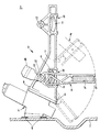
- the single figure shows the section through a bottom section of a plastic fuel tank, to which the housing of a suction jet pump is attached the level measuring unit arranged on the housing.
- the fuel tank 1 is only with a portion of its tank bottom 2 shown and has a level measuring unit 3 and one in a housing 4th trained suction jet pump, which is not explained in detail with its details becomes.
- the suction jet pump is used to deliver fuel from a container chamber, which is assigned to the container bottom 2, in another container chamber the fuel tank or in a baffle.
- the housing 4 of the suction jet pump is attached to the tank bottom 2 and carries Furthermore, the level measuring unit 3.
- the housing 4 is on the indicated connector 5 connected to the container bottom 2. But it could also be one Clip connection can be used to remove the case from the bottom of the container if necessary to be able to solve.
- the fuel tank 2 and the housing 4 of the suction jet pump consist of Plastic.
- the housing 4 with the container bottom can then preferably be used 2 also be welded.
- the fill level measuring unit 3 can also be detachable, for example via a clip connection 6 be arranged on the housing 4 of the suction jet pump.
- a clip connection 6 be arranged on the housing 4 of the suction jet pump.
- these Housing 4 of the suction jet pump and the support part 7 of the level measuring unit Plastic so these two parts can be welded together his.
- the suction jet pump and also the level measuring unit in the fuel tank with a comparatively low construction effort with simple assembly achieved.
- the one from the Housing 4 and the level measurement unit 3 existing assembly can by a corresponding opening on the top of the container is inserted into the container and be connected to its bottom, whereupon the opening the top of the container is welded to a lid.
- the level measuring unit 3 designed as a lever transmitter, the pivotable float arm 8 is made of plastic.
- Carrying part 7 formed a pocket 10 provided with recesses 9, into which a Resistor plate 11 of the measuring sensor system is used.
- the bag 10 can with be suitable edge projections, on the one hand, the resistance plate hold reliably, but nevertheless its simple assembly by plugging in allow.
- the recess 9 is used to reach through sliding contacts the illustrated embodiment are arranged on the float arm 8. Conversely, the resistance plate on the float arm and the Slip contacts could be provided on the support member 7.
- the bearing eyes 12 are on the float arm 8 and the associated bearing journal 13 molded onto the support member 7.
- the float is at least in the area adjacent to the bearing eyes 12 divided in a plane parallel to the drawing plane and can be expanded as far be that the bearing eyes 12 can be pushed over the journal 13.
- the reverse design with the pin would be on Float arm and corresponding bearing mounts on the support part possible.
- a pocket 14 for insertion and Lock the float 15 provided at the free end of the float arm 8 .
- the otherwise common bore for Bearing a float on an angled wire end of the float arm and the locking disc required for fixing is saved. Nevertheless, it is easy and safe to assemble and also good display accuracy possible.
Description
Die Erfindung bezieht sich auf einen Kraftstoffbehälter für Kraftfahrzeuge nach dem Oberbegriff des Patentanspruches 1.The invention relates to a fuel tank for motor vehicles the preamble of claim 1.
Bei einem bekannten derartigen Kraftstoffbehälter (DE 40 31 434 A1) ist in dem hochgezogenen Bereich des Satteltankes ein Stützteil befestigt, in das eine Reihe von Tragteilen für eine Kraftstoff-Förderpumpe, eine Saugstrahlpumpe, eine Umfüll-Leitung und eine als Hebelgeber ausgebildete Füllstandsmeßeinheit gesteckt werden können. Die eben erwähnten Einheiten erstrecken sich von ihrem Einsteckende jeweils relativ weit in die eine bzw. in die andere Behälterkammer. Das genaue Positionieren dieser Einheiten, insbesondere relativ zum Tankboden, ist einerseits wegen der gewählten Steckverbindungen, aber auch wegen des großen Abstandes von der Befestigungsstelle zur erwünschten Position des jeweiligen Teils, relativ schwierig. Die Vielzahl der Teile bedeuten einen erhöhten Kosten- und Montageaufwand. Die Teile sind bei der Herstellung toleranzempfindlich und können sich auch, etwa während der Montage, verbiegen, was zu Nachteilen im praktischen Betrieb, etwa einer ungenauen Anzeige des Füllstandes oder auch einer unvollständigen Absaugung von Kraftstoff, führen kann.In a known such fuel tank (DE 40 31 434 A1) is in the pulled up area of the saddle tank attached to a support in which a row of supporting parts for a fuel delivery pump, a suction jet pump, a transfer line and inserted a level measuring unit designed as a lever transmitter can be. The units just mentioned extend from their insertion end each relatively far into one or the other container chamber. The exact positioning of these units, especially relative to the tank bottom on the one hand because of the chosen plug connections, but also because of the large one Distance from the attachment point to the desired position of the respective Partly, relatively difficult. The large number of parts means an increased cost and Installation effort. The parts are sensitive to tolerances during manufacture and can also bend, for example during assembly, which has disadvantages in practice Operation, such as an inaccurate display of the level or one incomplete fuel extraction.
Es ist weiterhin bekannt (DE 41 21 320 C2), eine Saugstrahlpumpe und auch eine Füllstandsmeßeinheit an einem Deckelflansch zu befestigen, der mit einer entsprechenden Öffnung an der Oberseite des Tank verschraubt wird. Auch bei dieser Bauart ist es schwierig, die Teile positionsgenau zu montieren, die Teile in der richtigen Position abzustützen und Verbiegungen von Gestängeteilen zu vermeiden. It is also known (DE 41 21 320 C2), a suction jet pump and also one Filling level measuring unit to be attached to a cover flange with a corresponding Opening is screwed to the top of the tank. This one too In terms of design, it is difficult to assemble the parts precisely, the parts in the right way Support position and avoid bending of rod parts.
Der Erfindung liegt die Aufgabe zugrunde, einen Kraftstoffbehälter der vorausgesetzten Bauart zu schaffen, der mit weniger, einfacher zu montierenden Bauteilen eine genauere Positionierung der in den Tank einzubauenden Teile und damit auch eine größere Funktionssicherheit gewährleistet.The invention has for its object a fuel tank of the prerequisite To create the design with fewer, easier to assemble components a more precise positioning of the parts to be installed in the tank and thus also ensures greater functional reliability.
Diese Aufgabe wird erfindungsgemäß durch die im Patentanspruch 1 angegebenen Maßnahmen gelöst. Weitere vorteilhafte Einzelheiten der Erfindung sind Gegenstand von Unteransprüchen.This object is achieved by the one specified in claim 1 Measures solved. Further advantageous details of the invention are the subject of subclaims.
Die feste Anordnung des Gehäuses der Saugstrahlpumpe am Tankboden stellt eine bodennahe Position der Saugstrahlpumpe auch dann sicher, wenn beispielsweise die Behälterwandungen sich in einem gewissen Maß verformen. Durch die Anordnung der Füllstandsmeßeinheit an dem in seiner Lage genau fixierten Gehäuse der Saugstrahlpumpe ist auch die Füllstandsmeßeinheit sehr genau gegenüber dem Behälterboden positioniert.The fixed arrangement of the housing of the suction jet pump on the tank bottom provides a position close to the ground of the suction jet pump is also secure, for example if the container walls deform to a certain extent. Through the Arrangement of the level measuring unit on the housing, which is precisely fixed in its position the suction jet pump is also very precisely opposite the level measuring unit positioned the bottom of the container.
Die Befestigung des Gehäuses der Saugstrahlpumpe mit dem Behälterboden kann über eine Steck- oder Clipsverbindung erfolgen. Dadurch kann das Gehäuse unter Umständen auch für Reparaturzwecke vom Behälterboden gelöst werden. Es ist aber auch möglich, das Gehäuse der Saugstrahlpumpe mit dem Behälterboden zu verschweißen, da die Saugstrahlpumpen praktisch keinem Verschleiß unterliegen und über die Fahrzeuglebensdauer in der Regel nicht gewechselt werden.The attachment of the suction jet pump housing to the tank bottom can done via a plug or clip connection. This allows the housing to be under Under certain circumstances can also be detached from the bottom of the container for repair purposes. It is but also possible to close the housing of the suction jet pump with the tank bottom weld, since the suction jet pumps are practically not subject to wear and are usually not changed over the life of the vehicle.
In gleicher Weise kann die Füllstandsmeßeinheit lösbar, beispielsweise über eine Clipsverbindung an dem Gehäuse der Saugstrahlpumpe angeordnet sein. Es ist aber auch möglich, dieses Gehäuse und ein entsprechendes Tragteil der Füllstandsmeßeinheit, insbesondere wenn beide Teile aus Kunststoff bestehen, miteinander zu verschweißen oder unter Umständen auch aus einem Stück herzustellen.In the same way, the level measuring unit can be detached, for example via a Clip connection to be arranged on the housing of the suction jet pump. It is but also possible, this housing and a corresponding support part of the level measuring unit, especially if both parts are made of plastic with each other to be welded or, under certain circumstances, to be made from one piece.
Eine besonders unempfindliche Bauweise, die Verbiegungen während der Montage entgegenwirkt, ist erreichbar, wenn die Füllstandsmeßeinheit als Hebelgeber ausgebildet ist und dabei der schwenkbare Schwimmerarm aus Kunststoff gefertigt ist. Ein solcher Schwimmerarm ist nicht nur vergleichsweise leicht, er ist auch unempfindlich gegenüber kurzzeitigen geringeren Verformungen. Auch wenn anstelle eines Hebelgebers ein Tauchrohrgeber, ein elektrothermischer Geber oder anderweitige berührungslose Geber eingesetzt werden, ist es von Vorteil, das jeweilige Tragteil dieser Geber an dem Gehäuse der Saugstrahlpumpe zu befestigen.A particularly insensitive construction, the bending during assembly counteracts, is achievable if the level measuring unit as a lever is formed and the pivotable float arm is made of plastic is. Such a float arm is not only comparatively light, it is also insensitive against short-term lower deformations. Even if instead a lever sensor, a dip tube sensor, an electrothermal sensor or other contactless sensors are used, it is advantageous to the respective Fasten the support part of this encoder to the housing of the suction jet pump.
Die Erfindung und weitere vorteilhafte Einzelheiten der Erfindung sind im folgenden anhand eines in der Zeichnung dargestellten Ausführungsbeispiels näher erläutert. Die einzige Figur zeigt den Schnitt durch einen Bodenabschnitt eines Kunststoff-Kraftstoffbehälters, an dem das Gehäuse einer Saugstrahlpumpe befestigt ist mit der an dem Gehäuse angeordneten Füllstandsmeßeinheit.The invention and further advantageous details of the invention are as follows based on an embodiment shown in the drawing. The single figure shows the section through a bottom section of a plastic fuel tank, to which the housing of a suction jet pump is attached the level measuring unit arranged on the housing.
Der Kraftstoffbehälter 1 ist lediglich mit einem Abschnitt seines Behälterbodens 2
dargestellt und weist eine Füllstandsmeßeinheit 3 und eine in einem Gehäuse 4
ausgebildete Saugstrahlpumpe auf, die mit ihren Einzelheiten nicht gesondert erläutert
wird. Die Saugstrahlpumpe dient zum Fördern von Kraftstoff aus einer Behälterkammer,
der der Behälterboden 2 zugeordnet ist, in eine andere Behälterkammer
des Kraftstofftanks oder in einen Schwalltopf.The fuel tank 1 is only with a portion of its tank bottom 2
shown and has a
Das Gehäuse 4 der Saugstrahlpumpe ist am Behälterboden 2 befestigt und trägt
ferner die Füllstandsmeßeinheit 3. Das Gehäuse 4 ist über die angedeutete Steckverbindung
5 mit dem Behälterboden 2 verbunden. Es könnte aber auch eine
Clipsverbindung verwendet werden, um das Gehäuse im Bedarfsfall vom Behälterboden
lösen zu können.The housing 4 of the suction jet pump is attached to the tank bottom 2 and carries
Furthermore, the
Der Kraftstoffbehälter 2 und das Gehäuse 4 der Saugstrahlpumpe bestehen aus Kunststoff. Dabei kann dann vorzugsweise das Gehäuse 4 mit dem Behälterboden 2 auch verschweißt sein.The fuel tank 2 and the housing 4 of the suction jet pump consist of Plastic. The housing 4 with the container bottom can then preferably be used 2 also be welded.
Die Füllstandsmeßeinheit 3 kann auch lösbar, beispielsweise über eine Clipsverbindung
6 an dem Gehäuse 4 der Saugstrahlpumpe angeordnet sein. Sind das
Gehäuse 4 der Saugstrahlpumpe und das Tragteil 7 der Füllstandsmeßeinheit aus
Kunststoff gefertigt, so können auch diese beiden Teile miteinander verschweißt
sein. Es ist aber weiterhin auch möglich, das Gehäuse 4 der Saugstrahlpumpe und
das Tragteil 7 der Füllstandsmeßeinheit 3 aus einem einzigen Teil zu fertigen. In
allen Fällen wird eine sehr lagegenaue Positionierung der Saugstrahlpumpe und
auch der Füllstandsmeßeinheit im Kraftstoffbehälter mit einem vergleichsweise
geringen Bauaufwand bei gleichzeitig einfacher Montage erreicht. Die aus dem
Gehäuse 4 und der Füllstandsmeßeinheit 3 bestehende Baugruppe kann durch
eine entsprechende Öffnung auf der Oberseite des Behälters in den Behälter eingeführt
und mit dessen Boden verbunden werden, worauf dann die Öffnung auf
der Oberseite des Behälters mit einem Deckel verschweißt wird.The fill
Bei dem in der Zeichnung dargestellten Ausführungsbeispiel ist die Füllstandsmeßeinheit
3 als Hebelgeber ausgebildet, wobei der schwenkbare Schwimmerarm
8 aus Kunststoff gefertigt ist. Bei dem bevorzugten Ausführungsbeispiel ist am
Tragteil 7 eine mit Ausnehmungen 9 versehene Tasche 10 ausgebildet, in die ein
Widerstandsplättchen 11 der Meß-Sensorik eingesetzt ist. Die Tasche 10 kann mit
geeigneten Randvorsprüngen versehen sein, die einerseits das Widerstandsplättchen
zuverlässig halten, dennoch aber seine einfache Montage durch Einstecken
erlauben. Die Ausnehmung 9 dient zum Durchgriff von Schleifkontakten, die bei
dem dargestellten Ausführungsbeispiel am Schwimmerarm 8 angeordnet sind.
Umgekehrt könnte das Widerstandsplättchen auch am Schwimmerarm und die
Schleif-Kontakte könnten am Tragteil 7 vorgesehen werden.In the embodiment shown in the drawing, the
Bei dem dargestellten Ausführungsbeispiel sind die Lageraugen 12 am Schwimmerarm
8 und die zugeordneten Lagerzapfen 13 am Tragteil 7 angespritzt. Der
Schwimmerarm ist zumindest in dem an die Lageraugen 12 benachbarten Bereich
in einer zur Zeichenebene parallelen Ebene geteilt und kann so weit aufgeweitet
werden, daß die Lageraugen 12 über die Lagerzapfen 13 geschoben werden können.
Selbstverständlich wäre auch die umgekehrte Bauweise mit den Zapfen am
Schwimmerarm und entsprechenden Lageraufnahmen am Tragteil möglich.In the illustrated embodiment, the bearing
Am freien Ende des Schwimmerarmes 8 ist eine Tasche 14 zum Einschieben und
Einrasten des Schwimmers 15 vorgesehen. Die sonst häufig übliche Bohrung zum
Lagern eines Schwimmers an einem abgewinkelten Drahtende des Schwimmerarms
und die zur Festlegung erforderliche Rastscheibe werden eingespart.
Trotzdem ist eine einfache und sichere Montage und auch eine gute Anzeigegenauigkeit
möglich. At the free end of the
Obwohl durch die Werkstoffpaarung Kunststoff/Kunststoff bei den Lageraugen 12
und den Lagerzapfen 13 und durch das geringe Gewicht des aus Kunststoff bestehenden
Schwimmerarms 8 schon eine besondere Leichtgängigkeit des Hebelgebers
erreichbar ist, kann diese noch erhöht werden, wenn der Schwimmerarm 8
an seinem dem Schwimmer 15 abgewandten Ende mit einem Gegengewicht 16
versehen ist. Das Gegengewicht 16 kann angeclipst sein oder auch, wie aus der
Zeichnung entnehmbar, einstückig angespritzt werden.Although due to the material combination plastic / plastic in the bearing
Wie der Zeichnung schließlich noch zu entnehmen ist, kann die als Hebelgeber
ausgebildete Füllstandsmeßeinheit 3 außer dem bisher beschriebenen Schwimmerarm
8 noch den lediglich in strichlierten Linien angedeuteten Schwimmerarm 8'
aufweisen, wobei beide Schwimmerarme übereinander angeordnet sind. Zur Lagerung
dieses zweiten Schwimmerarmes 8' weist das Tragteil 7 an seinem oberen
Endbereich ebenfalls Lagerzapfen 13 und eine Tasche 10 zur Aufnahme eines
Widerstandsplättchens 11 auf.As the drawing shows, you can use it as a lever
trained
Claims (14)
- A fuel tank for motor vehicles comprising at least one level meter (3) and a sucking jet pump in a casing (4) and disposed near the tank bottom (2) and adapted to deliver fuel from a compartment of the tank to another compartment thereof,
characterised in that the casing (4) of the sucking jet pump is fastened to the tank bottom (2) and also holds the level sensor (3). - A fuel tank according to claim 1, characterised in that the casing (4) is connected to the tank bottom (2) by a plug-in connection (5) or a clip-on connection.
- A fuel tank according to claim 1, wherein both the tank and the pump casing are of plastics material, characterised in that the casing (4) is welded to the tank bottom (2).
- A fuel tank according to claim 1, characterised in that the level meter (3) is secured to the pump casing (4) in releasable manner, for example by a clip-on connection (6).
- A fuel tank according to claim 1, wherein the pump casing is of plastics material,
characterised in that the supporting structure (7) of the level meter (3) is of plastics material and is welded to the pump casing (4). - A fuel tank according to claim 1, characterised in that the pump casing (4) and the structure (7) supporting the level meter (3) are in one piece.
- A fuel tank according to claim 1, characterised in that the level meter (3) is a lever indicator.
- A fuel tank according to claims 5 and 7, characterised in that a pocket with recesses (9) through which a loop element extends is formed on the supporting structure (7) or on the float arm, and a resistance plate (11) or the like is inserted into the pocket.
- A fuel tank according to claim 8, characterised in that the resistance plate (11) is secured by a snap-in connection.
- A fuel tank according to claim 5 or 7, characterised in that the bearing eyelets (12) and/or the bearing pins (13) are injection-moulded on the supporting structure or on the float arm (8).
- A fuel tank according to claim 7, characterised in that a pocket for engaging the float is provided on the free end of the float arm (8).
- A fuel tank according to claim 7, characterised in that the float arm (8) has a counterweight (16) at its end remote from the float (15).
- A fuel tank according to claim 12, characterised in that the counterweight (16) is injection-moulded on the float arm (8).
- A fuel tank according to claim 7, characterised in that the lever indicator has two float arms (8, 8') disposed one above the other.
Applications Claiming Priority (2)
| Application Number | Priority Date | Filing Date | Title |
|---|---|---|---|
| DE19613893A DE19613893A1 (en) | 1996-04-06 | 1996-04-06 | Fuel tanks for vehicles |
| DE19613893 | 1996-04-06 |
Publications (3)
| Publication Number | Publication Date |
|---|---|
| EP0799990A2 EP0799990A2 (en) | 1997-10-08 |
| EP0799990A3 EP0799990A3 (en) | 1999-06-16 |
| EP0799990B1 true EP0799990B1 (en) | 2002-11-06 |
Family
ID=7790714
Family Applications (1)
| Application Number | Title | Priority Date | Filing Date |
|---|---|---|---|
| EP97104607A Expired - Lifetime EP0799990B1 (en) | 1996-04-06 | 1997-03-18 | Motor vehicle fuel tank |
Country Status (2)
| Country | Link |
|---|---|
| EP (1) | EP0799990B1 (en) |
| DE (2) | DE19613893A1 (en) |
Families Citing this family (2)
| Publication number | Priority date | Publication date | Assignee | Title |
|---|---|---|---|---|
| DE19842336C2 (en) * | 1998-09-16 | 2001-03-22 | Mannesmann Vdo Ag | Fuel tank for a motor vehicle |
| FR2808471B1 (en) * | 2000-05-03 | 2003-02-14 | Plastic Omnium Cie | FUEL TANK AND MANUFACTURING METHOD |
Family Cites Families (9)
| Publication number | Priority date | Publication date | Assignee | Title |
|---|---|---|---|---|
| GB2222392B (en) * | 1988-09-03 | 1990-09-05 | Delco Electronic Overseas Corp | Fuel pump reservoir assembly |
| US4939932A (en) * | 1989-03-28 | 1990-07-10 | Vdo Adolf Schindling Ag | Level measuring device |
| JP2684099B2 (en) * | 1989-10-20 | 1997-12-03 | 富士重工業株式会社 | 2-tank fuel tank device |
| US4945884A (en) * | 1989-10-24 | 1990-08-07 | General Motors Corporation | Modular fuel delivery system |
| DE4035321A1 (en) * | 1989-11-16 | 1991-05-23 | Volkswagen Ag | Level measurement device for liquid container, esp. motor vehicle - has pivoting support and float arms arranged to reduce sensitivity to container shape changes |
| DE4121320C1 (en) * | 1991-06-27 | 1992-07-16 | Bayerische Motoren Werke Ag, 8000 Muenchen, De | Car fuel tank with accelerator pump - has gas bubble catching or reducing device above accelerator pump |
| US5272918A (en) * | 1993-06-30 | 1993-12-28 | Ford Motor Company | Pivotal liquid level sensor assembly |
| FR2708996B1 (en) * | 1993-08-13 | 1998-01-16 | Volkswagen Ag | Device for measuring the filling level of a liquid tank, in particular a fuel tank of a motor vehicle. |
| DE4426035C2 (en) * | 1994-07-22 | 2000-08-17 | Mannesmann Vdo Ag | Fuel delivery device |
-
1996
- 1996-04-06 DE DE19613893A patent/DE19613893A1/en not_active Withdrawn
-
1997
- 1997-03-18 EP EP97104607A patent/EP0799990B1/en not_active Expired - Lifetime
- 1997-03-18 DE DE59708641T patent/DE59708641D1/en not_active Expired - Lifetime
Also Published As
| Publication number | Publication date |
|---|---|
| EP0799990A3 (en) | 1999-06-16 |
| EP0799990A2 (en) | 1997-10-08 |
| DE59708641D1 (en) | 2002-12-12 |
| DE19613893A1 (en) | 1997-10-09 |
Similar Documents
| Publication | Publication Date | Title |
|---|---|---|
| DE2740653C2 (en) | ||
| EP2059773A1 (en) | Fuel delivery unit with a filling level sensor operating with ultrasonic waves | |
| EP1047920B1 (en) | Level sensor | |
| EP1721133B1 (en) | Level sensor comprising a float for determining a fuel level in a fuel tank, and kit for such a level sensor | |
| DE19842336C2 (en) | Fuel tank for a motor vehicle | |
| EP0710821A1 (en) | Indicator for measuring liquid level in a container | |
| DE2830518C2 (en) | Level sensor, in particular for measuring the tank content in motor vehicles | |
| DE102004043717B4 (en) | Device for detecting a level | |
| EP0799990B1 (en) | Motor vehicle fuel tank | |
| DE102006056391B3 (en) | Navigation computer for motor vehicle, has gyro sensor for determining turning of vehicle around vertical axis, and base plate fastened in set of fastening planes of holder, and extends in different inclination angles to mounting plane | |
| DE19900378A1 (en) | Tank system is for motor vehicles has T-piece fitted to pump unit and has suction branches with one end of respective hoses connected to each, with other ends of hoses running into defined section of tank | |
| DE4206975C2 (en) | Level indicator in a plastic fuel tank | |
| DE4411961C2 (en) | Tank level sensor | |
| DE19927618A1 (en) | Mounting system for a hinged foot pedal used in a road vehicle system has a bearing that fits into moulded cavity | |
| DE102017011150B3 (en) | Level measuring device for a fuel tank of a vehicle | |
| DE3310704C1 (en) | Liquid level measuring device | |
| EP0658456B1 (en) | Jet pump unit | |
| EP0895068A2 (en) | Level sensor | |
| DE4426035C2 (en) | Fuel delivery device | |
| DE3313095C2 (en) | ||
| DE102005041338A1 (en) | Lock element for charging hole of washing liquid container used in vehicle windshield washer, has mechanical level indicator with float attached to filter | |
| DE102007000570A1 (en) | Fill level sensor for measuring filling level in fuel container, has retaining unit designed as U-shaped retaining bracket that encompasses retainer with recess in sections, where retaining bracket is made up flat material, metal or plastic | |
| WO2005022094A1 (en) | Lever-type sender for a fuel tank | |
| EP0173067A2 (en) | Device for signalling water, especially for oil and petrol tanks | |
| DE3926552C2 (en) |
Legal Events
| Date | Code | Title | Description |
|---|---|---|---|
| PUAI | Public reference made under article 153(3) epc to a published international application that has entered the european phase |
Free format text: ORIGINAL CODE: 0009012 |
|
| AK | Designated contracting states |
Kind code of ref document: A2 Designated state(s): DE FR GB |
|
| PUAL | Search report despatched |
Free format text: ORIGINAL CODE: 0009013 |
|
| AK | Designated contracting states |
Kind code of ref document: A3 Designated state(s): DE FR GB |
|
| RIC1 | Information provided on ipc code assigned before grant |
Free format text: 6F 02M 37/10 A, 6B 60K 15/06 B, 6F 02M 37/02 B |
|
| 17P | Request for examination filed |
Effective date: 19990514 |
|
| GRAG | Despatch of communication of intention to grant |
Free format text: ORIGINAL CODE: EPIDOS AGRA |
|
| GRAG | Despatch of communication of intention to grant |
Free format text: ORIGINAL CODE: EPIDOS AGRA |
|
| GRAH | Despatch of communication of intention to grant a patent |
Free format text: ORIGINAL CODE: EPIDOS IGRA |
|
| 17Q | First examination report despatched |
Effective date: 20020419 |
|
| GRAH | Despatch of communication of intention to grant a patent |
Free format text: ORIGINAL CODE: EPIDOS IGRA |
|
| GRAA | (expected) grant |
Free format text: ORIGINAL CODE: 0009210 |
|
| AK | Designated contracting states |
Kind code of ref document: B1 Designated state(s): DE FR GB |
|
| REG | Reference to a national code |
Ref country code: GB Ref legal event code: FG4D Free format text: NOT ENGLISH |
|
| GBT | Gb: translation of ep patent filed (gb section 77(6)(a)/1977) |
Effective date: 20021106 |
|
| REF | Corresponds to: |
Ref document number: 59708641 Country of ref document: DE Date of ref document: 20021212 |
|
| ET | Fr: translation filed | ||
| PLBE | No opposition filed within time limit |
Free format text: ORIGINAL CODE: 0009261 |
|
| STAA | Information on the status of an ep patent application or granted ep patent |
Free format text: STATUS: NO OPPOSITION FILED WITHIN TIME LIMIT |
|
| 26N | No opposition filed |
Effective date: 20030807 |
|
| PGFP | Annual fee paid to national office [announced via postgrant information from national office to epo] |
Ref country code: DE Payment date: 20140319 Year of fee payment: 18 |
|
| REG | Reference to a national code |
Ref country code: FR Ref legal event code: PLFP Year of fee payment: 19 |
|
| PGFP | Annual fee paid to national office [announced via postgrant information from national office to epo] |
Ref country code: GB Payment date: 20150326 Year of fee payment: 19 |
|
| PGFP | Annual fee paid to national office [announced via postgrant information from national office to epo] |
Ref country code: FR Payment date: 20150330 Year of fee payment: 19 |
|
| REG | Reference to a national code |
Ref country code: DE Ref legal event code: R119 Ref document number: 59708641 Country of ref document: DE |
|
| PG25 | Lapsed in a contracting state [announced via postgrant information from national office to epo] |
Ref country code: DE Free format text: LAPSE BECAUSE OF NON-PAYMENT OF DUE FEES Effective date: 20151001 |
|
| GBPC | Gb: european patent ceased through non-payment of renewal fee |
Effective date: 20160318 |
|
| REG | Reference to a national code |
Ref country code: FR Ref legal event code: ST Effective date: 20161130 |
|
| PG25 | Lapsed in a contracting state [announced via postgrant information from national office to epo] |
Ref country code: GB Free format text: LAPSE BECAUSE OF NON-PAYMENT OF DUE FEES Effective date: 20160318 Ref country code: FR Free format text: LAPSE BECAUSE OF NON-PAYMENT OF DUE FEES Effective date: 20160331 |