EP0799425B1 - Gradiometer - Google Patents
Gradiometer Download PDFInfo
- Publication number
- EP0799425B1 EP0799425B1 EP95942019A EP95942019A EP0799425B1 EP 0799425 B1 EP0799425 B1 EP 0799425B1 EP 95942019 A EP95942019 A EP 95942019A EP 95942019 A EP95942019 A EP 95942019A EP 0799425 B1 EP0799425 B1 EP 0799425B1
- Authority
- EP
- European Patent Office
- Prior art keywords
- squid
- gradiometer
- concentrator
- squids
- flow concentrator
- Prior art date
- Legal status (The legal status is an assumption and is not a legal conclusion. Google has not performed a legal analysis and makes no representation as to the accuracy of the status listed.)
- Expired - Lifetime
Links
Images


Classifications
-
- G—PHYSICS
- G01—MEASURING; TESTING
- G01R—MEASURING ELECTRIC VARIABLES; MEASURING MAGNETIC VARIABLES
- G01R33/00—Arrangements or instruments for measuring magnetic variables
- G01R33/02—Measuring direction or magnitude of magnetic fields or magnetic flux
- G01R33/035—Measuring direction or magnitude of magnetic fields or magnetic flux using superconductive devices
- G01R33/0354—SQUIDS
- G01R33/0358—SQUIDS coupling the flux to the SQUID
-
- G—PHYSICS
- G01—MEASURING; TESTING
- G01R—MEASURING ELECTRIC VARIABLES; MEASURING MAGNETIC VARIABLES
- G01R33/00—Arrangements or instruments for measuring magnetic variables
- G01R33/02—Measuring direction or magnitude of magnetic fields or magnetic flux
- G01R33/022—Measuring gradient
-
- Y—GENERAL TAGGING OF NEW TECHNOLOGICAL DEVELOPMENTS; GENERAL TAGGING OF CROSS-SECTIONAL TECHNOLOGIES SPANNING OVER SEVERAL SECTIONS OF THE IPC; TECHNICAL SUBJECTS COVERED BY FORMER USPC CROSS-REFERENCE ART COLLECTIONS [XRACs] AND DIGESTS
- Y10—TECHNICAL SUBJECTS COVERED BY FORMER USPC
- Y10S—TECHNICAL SUBJECTS COVERED BY FORMER USPC CROSS-REFERENCE ART COLLECTIONS [XRACs] AND DIGESTS
- Y10S505/00—Superconductor technology: apparatus, material, process
- Y10S505/825—Apparatus per se, device per se, or process of making or operating same
- Y10S505/842—Measuring and testing
- Y10S505/843—Electrical
- Y10S505/845—Magnetometer
- Y10S505/846—Magnetometer using superconductive quantum interference device, i.e. squid
Definitions
- the invention relates to a gradiometer with two each a SQUIDs containing a SQUID loop.
- gradiometers for suppressing interference fields.
- Such disturbances include fluctuations in the earth's field as well as the fields that come about as a result of artificial, electromagnetic pollution of our environment, such as the 50 Hz alternating fields.
- Gradiometers based on low-T c materials are already known and can be produced with relatively little effort.
- Ductile wires are available for this purpose, with the help of which it is possible to produce closed coil pairs with partly opposite winding directions, which leads to the elimination of fields with a low gradient. No suitable wires are currently available in the area of high-TC materials.
- the gradiometer according to the invention has the special Advantage of having a certain desired base length of the gradiometer using suitable design measures can be adjusted without increasing it of inductance and a related reduction of the gradiometer signal is coming.
- each River concentrator in the perpendicular to its surface Mirror plane of symmetry to form each other electrically isolated flow concentrator parts an electrically isolated layer connecting the two parts. This will shield the currents at the edge of each Flow concentrator parts each passed the SQUID loops and generate the same at the location of the SQUID large, concentrated magnetic fields.
- the flux concentrator is then designed so that it also encloses this SQUID. That way gets one gradiometer with several different ones basic lengths with spatial orientations, the each represent a single gradiometer.
- the gradiometer is particularly advantageous by the characteristic Part listed according to claim 4. In this case you get a planar gradiometer, the in two independent, spatial orientations for determination of magnetic fields or magnetic field gradients is.
- a particularly advantageous embodiment of the gradiometer is obtained according to claim 6 by the material to form the flow concentrator and / or the adjustment plate a high temperature superconductor (HTSL) was chosen becomes.
- HTSL high temperature superconductor
- a washer SQUID such as that from Appl. Phys. Lett. 60 (1992) 645, or even exclusively washer SQUIDs, preferably as HTSL washer SQUID, has a particularly advantageous producible in thin film technology Gradiometer.
- the flow concentrator can be used as HTSL thin film applied to a substrate Come into play.
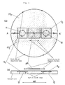
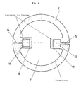
- Figure 1 is a schematic plan view (Figure la) and in cross section along the line AA '( Figure 1b) Gradiometer with a solid circular disc Shown concentrator.
- This concentrator made of HTSL material became procedural manufactured as follows:
- a circular disk shape was cut from a solid piece of HTSL, here YBa 2 Cu 3 O 7 ; this was separated into two equally large, semicircular disk-shaped parts, both of which were provided with semicircular disk-shaped openings at the dividing line AA 'at a distance of the base length L 1 from one another; finally, both parts were joined with the aid of an electrically insulating adhesive to form the concentrator F as a circular disk shape with two circular disk-shaped openings 11 and 12 at a distance L 1 .
- FIG. 1 a shows the two semicircular disk-shaped parts FT 1 and FT 2 with circular disk-shaped openings 11 and 12 at a distance L 1 .
- the openings 11 and 12 are designed such that they have corresponding depressions on the upper side of the concentrator F for receiving two cuboid washer SQUIDs S 1 and S 2 .
- a displaceable adjustment plate AP made of HTSL is provided in the area between the positions of the two SQUIDs S 1 and S 2 .
- the plate AP is rectangular in this special case, although other shapes could also be selected.
- the superconducting shielding currents which form in the concentrator F at the operating temperatures are indicated in FIG. 1 a in the form of loops provided with arrows.
- the currents form at the edge of the respective semicircular disc-shaped part FT 1 and FT 2 and in this way one obtains at these openings 11 and 12 because of the opposite flow direction at the respective opening 11 and 12 in the two parts FT 1 and FT 2.
- 12 shows a ring current which, when the SQUIDs S 1 and S 2 are positioned in the respective recess in the concentrator F, causes the magnetic field to focus in the SQUID loop of the respective SQUID.
- the massive concentrator F had a diameter of 50 mm with a circular disk thickness of 3 mm.
- the openings 11 and 12 each had a diameter of 6 mm.
- the base length L 1 was chosen to be 30 mm in this case.
- the rectangular substrates S 1 and S 2 containing the respective Washer-SQUID were 10 * 10 mm 2 in size, the recesses formed for this had only a slightly larger value.
- this gradiometer When choosing different geometries for the parts of this gradiometer can have the desired gradiometer properties corresponding gradiometer with more or less long base length can be obtained.
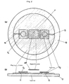
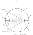
- FIG. 2 schematically shows a gradiometer which has a flux concentrator F using thin-film technology.
- a circular YBa 2 CU 3 O 7 layer was formed on a circular substrate 13 using known masking technology, said layer having two openings 11 and 12 and each having a web 14 and 15 free of HTSL up to the edge of the circular layer F were provided.
- shielding currents form at the edge of this thin-film flux concentrator F, which form ring currents comparable to the currents in the gradiometer according to FIG. 1 at the respective openings 11 and 12 (diameter 6 mm).
- the circular layer F had a diameter of 48 mm, the width of the webs 14 and 15 was 6 ⁇ m, their length was about 10 mm.
- FIG. 3 shows the lateral shape of the thin-film concentrator of the gradiometer shown in FIG. 2.
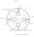
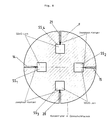
- a variant of this gradiometer with thin film concentrator F can instead of two (11, 12), now four SQUID recesses 11, 12, 16 and 17 included, as schematically in Figure 4 for one accordingly manufactured in thin-film technology Flow concentrator F shown in plan view.
- Flow concentrator F shown in plan view.
- the concentrator should be designed so that the Ring currents to the edge of the respective opening (11, 12, 16, 17) for the respective SQUID become.
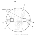
- FIG. 5 Another variant of the concentrator had a lateral layer structure, as shown hatched in FIG. 5.
- HTSL material in the central region F 'of the circular layer F was largely dispensed with here.
- the HTSL web 18 or 19, which runs around the inside of the respective opening 11, 12 in FIG. 5, had a width of only 3 mm.
- the openings shown here perform the function of the flow focusing 11, 12, 16, 17 as well as the SQUID function SS 1 , ... at the same time.
- the respective small connecting line between the respective rectangular opening 11, 12, 16, 17 and the respective web 14, 15, 20, 21 connecting this to the edge of the concentrator schematically represents the SQUID function SS 1 , ... provided Josephson contact.
- the openings 11, 12, 16, 17 and SS 1 ... also appear to be approximately 10 * 10 mm 2 in size; in fact, the openings 11, 12, 16, 17 and SS 1 , ... in FIGS. 7 to 10, however, are only 200 * 200 ⁇ m 2 in order to form the SQUID function SS 1 , ... Gradiometers with 20 * 20 ⁇ m 2 large SQUID functions were also manufactured.
- FIG. 8 shows a gradiometer in thin-film technology with a circular concentrator F and four SQUID functions SS 1 , SS 2 , SS 3 and SS 4 integrated in it, in a top view.
- FIG. 9 shows a variant of the gradiometer with two SQUID functions SS 1 and SS 2 integrated in a thin-film concentrator F.
- FIG. 9 shows a variant of the gradiometer with two SQUID functions SS 1 and SS 2 integrated in a thin-film concentrator F.
- Figure 10 shows Figure 10.
- the embodiments of the gradiometer given here are only examples of possible embodiments of the invention. Geometrically, many further combinations of individual elements of the gradiometer variants described here are conceivable, depending on the desired or predetermined boundary conditions.
Landscapes
- Physics & Mathematics (AREA)
- Condensed Matter Physics & Semiconductors (AREA)
- General Physics & Mathematics (AREA)
- Measuring Magnetic Variables (AREA)
- Superconductor Devices And Manufacturing Methods Thereof (AREA)
- Measurement And Recording Of Electrical Phenomena And Electrical Characteristics Of The Living Body (AREA)
Description
In Gegensatz zu der Schichtstruktur des Konzentrators zu Figur 4 wurde hier auf HTSL-Material im mittleren Bereich F' der kreisförmigen Schicht F weitgehend verzichtet. Der die jeweilige Öffnung 11, 12 innenliegend umlaufende HTSL-Steg 18 bzw. 19 in der Figur 5 hatte eine Breite von nur noch 3 mm.
Claims (7)
- Gradiometer mit zwei jeweils eine SQUID-Schleife (SS1, SS2) enthaltenden SQUIDs (S1, S2), wobei die SQUIDS (S1, S2) zueinander so angeordnet sind, daß die SQUID-Schleifen (SS1, SS2) um eine Basislänge (L1) voneinander entfernt in einer Ebene (E) liegen, dadurch gekennzeichnet, daßein diese Ebene enthaltender flächiger Flußkonzentrator (F) beide SQUID-Schleifen (SS1, SS2) umschließt undder Flußkonzentrator (F) zu der die Mitten der beiden SQUID-Schleifen (SS1, SS2) miteinander verbindende Basislänge spiegelsymmetrisch ausgebildet ist.
- Gradiometer nach Anspruch 1,
dadurch gekennzeichnet,
daß der Flußkonzentrator (F) in der zu seiner Oberfläche senkrechten Spiegelsymmetrieebene zur Ausbildung voneinander elektrisch isolierter Flußkonzentratorteilen (FT1, FT2) eine elektrisch isolierende, die beiden Teile verbindende Schicht aufweist. - Gradiometer nach einem der Ansprüche 1 oder 2,
gekennzeichnet durch
wenigstens einen weiteren SQUID (S3), deren SQUID-Spule in der Ebene der beiden ersten SQUID-Spulen (SS1, SS2) liegt, wobei der Flußkonzentrator (F) so ausgebildet ist, daß er diesen SQUID (S3) umschließt. - Gradiometer nach einem der Ansprüche 1 bis 3,
gekennzeichnet durch wenigstens ein Paar weiterer in der SQUID-Schleifen-Ebene der ersten liegenden SQUIDs (S3, S4), das zur Orientierung der Basislänge der ersten SQUID nicht parallel, insbesondere senkrecht, ausgerichtet ist. - Gradiometer nach einem der vorhergehenden Ansprüche, gekennzeichnet durch eine supraleitende Abgleichplatte (AP), die auf dem Flußkonzentrator (F) verschiebbar angeordnet ist.
- Gradiometer nach einem der vorhergehenden Ansprüche
gekennzeichnet durch
hochtemperatur-supraleitendes Material (HTSL) zur Bildung des Flußkonzentrators (F) oder der Abgleichplatte (AP). - Gradiometer nach einem der vorhergehenden Ansprüche
gekennzeichnet durch
wenigstens einen Washer-SQUID.
Applications Claiming Priority (3)
| Application Number | Priority Date | Filing Date | Title |
|---|---|---|---|
| DE4445700 | 1994-12-21 | ||
| DE4445700A DE4445700A1 (de) | 1994-12-21 | 1994-12-21 | Gradiometer |
| PCT/DE1995/001816 WO1996019736A1 (de) | 1994-12-21 | 1995-12-14 | Gradiometer |
Publications (2)
| Publication Number | Publication Date |
|---|---|
| EP0799425A1 EP0799425A1 (de) | 1997-10-08 |
| EP0799425B1 true EP0799425B1 (de) | 1999-02-24 |
Family
ID=6536529
Family Applications (1)
| Application Number | Title | Priority Date | Filing Date |
|---|---|---|---|
| EP95942019A Expired - Lifetime EP0799425B1 (de) | 1994-12-21 | 1995-12-14 | Gradiometer |
Country Status (5)
| Country | Link |
|---|---|
| US (1) | US5901453A (de) |
| EP (1) | EP0799425B1 (de) |
| JP (1) | JPH10511457A (de) |
| DE (2) | DE4445700A1 (de) |
| WO (1) | WO1996019736A1 (de) |
Families Citing this family (9)
| Publication number | Priority date | Publication date | Assignee | Title |
|---|---|---|---|---|
| DE19727772A1 (de) * | 1997-06-30 | 1999-01-28 | Forschungszentrum Juelich Gmbh | Magnetflußsensor mit ringförmiger Sonde |
| US6344742B1 (en) * | 1997-11-07 | 2002-02-05 | Sumitomo Electric Industries, Ltd. | Magnetic field sensor having a flux guide to increase the effective capture area |
| US6526668B1 (en) * | 1999-03-11 | 2003-03-04 | Microtool, Inc. | Electronic level |
| US6801136B1 (en) * | 1999-10-01 | 2004-10-05 | Gas Research Institute | Method of reducing noise in a borehole electromagnetic telemetry system |
| KR100364784B1 (ko) * | 2000-02-16 | 2002-12-16 | 엘지전자 주식회사 | 자장 측정 장치 |
| WO2002027332A2 (en) * | 2000-08-29 | 2002-04-04 | Cardiomag Imaging, Inc. | High balance gradiometer |
| EP1386004A4 (de) | 2001-04-05 | 2005-02-16 | Ribozyme Pharm Inc | Modulation der mit der entzündungsausbreitung und dem neuritenauswuchs assoziierten genexpression unter verwendung von technologien auf nukleinsäurebasis |
| WO2011057146A1 (en) * | 2009-11-06 | 2011-05-12 | Scientific Nanomedicine, Inc. | Detection, measurement, and imaging of cells such as cancer and other biologic substances using targeted nanoparticles and magnetic properties thereof |
| GB2540146A (en) | 2015-07-06 | 2017-01-11 | Univ Loughborough | Superconducting magnetic sensor |
Family Cites Families (13)
| Publication number | Priority date | Publication date | Assignee | Title |
|---|---|---|---|---|
| US4613816A (en) * | 1984-04-03 | 1986-09-23 | Geo-Sensors Corporation | Cryogenic magnetic probe having new substrate |
| DE3515237A1 (de) * | 1985-04-26 | 1986-10-30 | Siemens AG, 1000 Berlin und 8000 München | Vorrichtung zur messung schwacher magnetfelder mit wenigstens einem dc-squid |
| CA1220279A (en) * | 1985-06-20 | 1987-04-07 | Her Majesty The Queen In Right Of Canada As Represented By The Minister Of National Defence Of Her Majesty's Canadian Government | Precision magnetometer orientation device |
| EP0210489B2 (de) * | 1985-07-22 | 1993-11-18 | Siemens Aktiengesellschaft | Vielkanalige Vorrichtung zur Messung schwacher Magnetfelder |
| US5218297A (en) * | 1988-02-05 | 1993-06-08 | Hitachi, Ltd. | Superconductive quantum interference device in high temperature environments having reduced inductance and improved thermal noise response |
| DE3911195A1 (de) * | 1988-04-06 | 1989-10-19 | Hitachi Ltd | Flussmesser und verfahren fuer dessen herstellung |
| WO1990000742A1 (en) * | 1988-07-11 | 1990-01-25 | UNITED STATES GOVERNMENT, as represented by THE NATIONAL AERONAUTICS AND SPACE ADMINISTRATION OFFICE OF ASSOCIATE GENERAL COUNSEL (INTELLECTUAL PRO PERTY) | Planar thin film squid with integral flux concentrator |
| JPH03264874A (ja) * | 1990-03-15 | 1991-11-26 | Shin Gijutsu Jigyodan | 高感度磁束計 |
| US5053834A (en) * | 1990-08-31 | 1991-10-01 | Quantum Magnetics, Inc. | High symmetry dc SQUID system |
| JP2764115B2 (ja) * | 1991-02-26 | 1998-06-11 | セイコーインスツルメンツ株式会社 | 高感度磁場検出器の製造方法 |
| JPH05297089A (ja) * | 1992-04-20 | 1993-11-12 | Sumitomo Electric Ind Ltd | 磁気センサ |
| US5625290A (en) * | 1994-02-23 | 1997-04-29 | Micontech, Inc. | Complex superconducting quantum interference device and circuit |
| US5672967A (en) * | 1995-09-19 | 1997-09-30 | Southwest Research Institute | Compact tri-axial fluxgate magnetometer and housing with unitary orthogonal sensor substrate |
-
1994
- 1994-12-21 DE DE4445700A patent/DE4445700A1/de not_active Withdrawn
-
1995
- 1995-12-14 WO PCT/DE1995/001816 patent/WO1996019736A1/de not_active Ceased
- 1995-12-14 EP EP95942019A patent/EP0799425B1/de not_active Expired - Lifetime
- 1995-12-14 JP JP8519421A patent/JPH10511457A/ja active Pending
- 1995-12-14 DE DE59505152T patent/DE59505152D1/de not_active Expired - Fee Related
- 1995-12-14 US US08/860,986 patent/US5901453A/en not_active Expired - Fee Related
Also Published As
| Publication number | Publication date |
|---|---|
| DE4445700A1 (de) | 1996-06-27 |
| US5901453A (en) | 1999-05-11 |
| DE59505152D1 (en) | 1999-04-01 |
| WO1996019736A1 (de) | 1996-06-27 |
| EP0799425A1 (de) | 1997-10-08 |
| JPH10511457A (ja) | 1998-11-04 |
Similar Documents
| Publication | Publication Date | Title |
|---|---|---|
| EP0111827B1 (de) | Vorrichtung zur mehrkanaligen Messung schwacher, sich ändernder Magnetfelder und Verfahren zu ihrer Herstellung | |
| DE69329690T2 (de) | Ein Quanteninterferometer mit Oxyd-Supraleiter verwendendem planaren Magnetismus-Sensor | |
| EP2443469B1 (de) | Elektrische widerstandselemente und messsystem zur messung zeitveränderlicher magnetischer felder oder feldgradienten | |
| DE69019418T2 (de) | Squid-Magnetometer integrierter Art und Anordnung zu dessen Anwendung für biomagnetische Messungen. | |
| DE68922457T2 (de) | Ein Supraleiter zur Magnetfeldabschirmung. | |
| DE69101788T2 (de) | Hochsymmetrischer gleichstrom-squid. | |
| DE102011120784B4 (de) | Magnetfeldsensor mit Hochtemperatur-Supraleiter und Herstellungsverfahren dafür | |
| EP0210489B1 (de) | Vielkanalige Vorrichtung zur Messung schwacher Magnetfelder | |
| EP0246419A1 (de) | SQUID-Magnetometer für eine Vorrichtung zur Messung schwacher Magnetfelder | |
| DE69008945T3 (de) | Gerät für die Anwendung von Supraleitfähigkeit. | |
| EP0799425B1 (de) | Gradiometer | |
| EP0386824B1 (de) | Supraleitendes Gradiometer zur Messung schwacher Magnetfelder und ein Verfahren zu seiner Herstellung | |
| DE69120043T2 (de) | Aufnehmerspule für Magnetfeldmessung | |
| EP0184670B1 (de) | Verfahren zur Herstellung eines supraleitenden Gradiometers mit dreidimensionaler Struktur für eine Vorrichtung zur Messung schwacher Magnetfelder | |
| DE69838208T2 (de) | Magnetsensor mit Supraleiter | |
| DE69125129T2 (de) | Supraleitende Quanten-Interferenz-Einrichtung aus supraleitender oxydischer Dünnschicht | |
| DE69123427T2 (de) | Supraleitende Quanteninterferenzanordnung | |
| DE69322305T2 (de) | Planares Quanteninterferometer mit Oxid-Supraleiter | |
| DE2926786C2 (de) | Bauelement mit durch ein Magnetfeld steuerbaren Widerstand und Verwendung | |
| DE19509230C2 (de) | Hochsymmetrische Gradiometer-SQUID-Einrichtung mit Leiterbahnen aus Hoch-T¶c¶-Supraleitermaterial | |
| DE112018005423B4 (de) | Magnetfeld-messelement, magnetfeld-messvorrichtung und magnetfeld-messsystem | |
| DE10041797C2 (de) | Magnetfeldsensitive Dünnfilmsensoreinrichtung mit linearem Sensorelement und Flussantenne | |
| EP0890113A2 (de) | ANORDNUNG ZUR ANKOPPLUNG EINES rf-SQUID-MAGNETOMETERS AN EINEN SUPRALEITENDEN TANKSCHWINGKREIS | |
| DE19948618A1 (de) | Magnetfeldsensitive Sensoreinrichtung mit einer Array-Anordnung mehrerer Sensoreinheiten | |
| DE4433331C2 (de) | Magnetfeldempfindliche SQUID-Sensoreinrichtung mit Flußtransformator unter Verwendung von Hoch-T¶c¶-Supraleitermaterial |
Legal Events
| Date | Code | Title | Description |
|---|---|---|---|
| PUAI | Public reference made under article 153(3) epc to a published international application that has entered the european phase |
Free format text: ORIGINAL CODE: 0009012 |
|
| 17P | Request for examination filed |
Effective date: 19970624 |
|
| AK | Designated contracting states |
Kind code of ref document: A1 Designated state(s): BE DE FR GB IT NL |
|
| 17Q | First examination report despatched |
Effective date: 19971106 |
|
| GRAG | Despatch of communication of intention to grant |
Free format text: ORIGINAL CODE: EPIDOS AGRA |
|
| GRAG | Despatch of communication of intention to grant |
Free format text: ORIGINAL CODE: EPIDOS AGRA |
|
| GRAH | Despatch of communication of intention to grant a patent |
Free format text: ORIGINAL CODE: EPIDOS IGRA |
|
| GRAH | Despatch of communication of intention to grant a patent |
Free format text: ORIGINAL CODE: EPIDOS IGRA |
|
| GRAA | (expected) grant |
Free format text: ORIGINAL CODE: 0009210 |
|
| AK | Designated contracting states |
Kind code of ref document: B1 Designated state(s): BE DE FR GB IT NL |
|
| REF | Corresponds to: |
Ref document number: 59505152 Country of ref document: DE Date of ref document: 19990401 |
|
| ET | Fr: translation filed | ||
| ITF | It: translation for a ep patent filed | ||
| GBT | Gb: translation of ep patent filed (gb section 77(6)(a)/1977) |
Effective date: 19990521 |
|
| PGFP | Annual fee paid to national office [announced via postgrant information from national office to epo] |
Ref country code: DE Payment date: 19991119 Year of fee payment: 5 |
|
| PGFP | Annual fee paid to national office [announced via postgrant information from national office to epo] |
Ref country code: GB Payment date: 19991126 Year of fee payment: 5 |
|
| PGFP | Annual fee paid to national office [announced via postgrant information from national office to epo] |
Ref country code: FR Payment date: 19991217 Year of fee payment: 5 |
|
| PGFP | Annual fee paid to national office [announced via postgrant information from national office to epo] |
Ref country code: NL Payment date: 19991223 Year of fee payment: 5 Ref country code: BE Payment date: 19991223 Year of fee payment: 5 |
|
| PLBE | No opposition filed within time limit |
Free format text: ORIGINAL CODE: 0009261 |
|
| STAA | Information on the status of an ep patent application or granted ep patent |
Free format text: STATUS: NO OPPOSITION FILED WITHIN TIME LIMIT |
|
| 26N | No opposition filed | ||
| PG25 | Lapsed in a contracting state [announced via postgrant information from national office to epo] |
Ref country code: GB Free format text: LAPSE BECAUSE OF NON-PAYMENT OF DUE FEES Effective date: 20001214 |
|
| PG25 | Lapsed in a contracting state [announced via postgrant information from national office to epo] |
Ref country code: BE Free format text: LAPSE BECAUSE OF NON-PAYMENT OF DUE FEES Effective date: 20001231 |
|
| BERE | Be: lapsed |
Owner name: FORSCHUNGSZENTRUM JULICH G.M.B.H. Effective date: 20001231 |
|
| PG25 | Lapsed in a contracting state [announced via postgrant information from national office to epo] |
Ref country code: NL Free format text: LAPSE BECAUSE OF NON-PAYMENT OF DUE FEES Effective date: 20010701 |
|
| GBPC | Gb: european patent ceased through non-payment of renewal fee |
Effective date: 20001214 |
|
| PG25 | Lapsed in a contracting state [announced via postgrant information from national office to epo] |
Ref country code: FR Free format text: LAPSE BECAUSE OF NON-PAYMENT OF DUE FEES Effective date: 20010831 |
|
| NLV4 | Nl: lapsed or anulled due to non-payment of the annual fee |
Effective date: 20010701 |
|
| REG | Reference to a national code |
Ref country code: FR Ref legal event code: ST |
|
| PG25 | Lapsed in a contracting state [announced via postgrant information from national office to epo] |
Ref country code: DE Free format text: LAPSE BECAUSE OF NON-PAYMENT OF DUE FEES Effective date: 20011002 |
|
| PG25 | Lapsed in a contracting state [announced via postgrant information from national office to epo] |
Ref country code: IT Free format text: LAPSE BECAUSE OF NON-PAYMENT OF DUE FEES Effective date: 20051214 |