EP0798724A2 - Aufzeichnungs- und/oder Wiedergabegerät mit optischer Scheibe - Google Patents
Aufzeichnungs- und/oder Wiedergabegerät mit optischer Scheibe Download PDFInfo
- Publication number
- EP0798724A2 EP0798724A2 EP97201754A EP97201754A EP0798724A2 EP 0798724 A2 EP0798724 A2 EP 0798724A2 EP 97201754 A EP97201754 A EP 97201754A EP 97201754 A EP97201754 A EP 97201754A EP 0798724 A2 EP0798724 A2 EP 0798724A2
- Authority
- EP
- European Patent Office
- Prior art keywords
- recording
- disc
- recorded
- digital data
- record
- Prior art date
- Legal status (The legal status is an assumption and is not a legal conclusion. Google has not performed a legal analysis and makes no representation as to the accuracy of the status listed.)
- Withdrawn
Links
- 230000003287 optical effect Effects 0.000 title description 85
- 230000015654 memory Effects 0.000 claims description 38
- 230000002093 peripheral effect Effects 0.000 abstract 1
- 230000005236 sound signal Effects 0.000 description 12
- 230000006835 compression Effects 0.000 description 7
- 238000007906 compression Methods 0.000 description 7
- 238000010276 construction Methods 0.000 description 6
- 238000000034 method Methods 0.000 description 6
- 238000010586 diagram Methods 0.000 description 4
- 230000005540 biological transmission Effects 0.000 description 1
- 238000005516 engineering process Methods 0.000 description 1
- 238000005070 sampling Methods 0.000 description 1
Images


Classifications
-
- G—PHYSICS
- G11—INFORMATION STORAGE
- G11B—INFORMATION STORAGE BASED ON RELATIVE MOVEMENT BETWEEN RECORD CARRIER AND TRANSDUCER
- G11B20/00—Signal processing not specific to the method of recording or reproducing; Circuits therefor
- G11B20/00007—Time or data compression or expansion
-
- G—PHYSICS
- G11—INFORMATION STORAGE
- G11B—INFORMATION STORAGE BASED ON RELATIVE MOVEMENT BETWEEN RECORD CARRIER AND TRANSDUCER
- G11B11/00—Recording on or reproducing from the same record carrier wherein for these two operations the methods are covered by different main groups of groups G11B3/00 - G11B7/00 or by different subgroups of group G11B9/00; Record carriers therefor
- G11B11/10—Recording on or reproducing from the same record carrier wherein for these two operations the methods are covered by different main groups of groups G11B3/00 - G11B7/00 or by different subgroups of group G11B9/00; Record carriers therefor using recording by magnetic means or other means for magnetisation or demagnetisation of a record carrier, e.g. light induced spin magnetisation; Demagnetisation by thermal or stress means in the presence or not of an orienting magnetic field
- G11B11/105—Recording on or reproducing from the same record carrier wherein for these two operations the methods are covered by different main groups of groups G11B3/00 - G11B7/00 or by different subgroups of group G11B9/00; Record carriers therefor using recording by magnetic means or other means for magnetisation or demagnetisation of a record carrier, e.g. light induced spin magnetisation; Demagnetisation by thermal or stress means in the presence or not of an orienting magnetic field using a beam of light or a magnetic field for recording by change of magnetisation and a beam of light for reproducing, i.e. magneto-optical, e.g. light-induced thermomagnetic recording, spin magnetisation recording, Kerr or Faraday effect reproducing
- G11B11/1055—Disposition or mounting of transducers relative to record carriers
- G11B11/10556—Disposition or mounting of transducers relative to record carriers with provision for moving or switching or masking the transducers in or out of their operative position
- G11B11/10563—Access of indexed parts
-
- G—PHYSICS
- G11—INFORMATION STORAGE
- G11B—INFORMATION STORAGE BASED ON RELATIVE MOVEMENT BETWEEN RECORD CARRIER AND TRANSDUCER
- G11B11/00—Recording on or reproducing from the same record carrier wherein for these two operations the methods are covered by different main groups of groups G11B3/00 - G11B7/00 or by different subgroups of group G11B9/00; Record carriers therefor
- G11B11/10—Recording on or reproducing from the same record carrier wherein for these two operations the methods are covered by different main groups of groups G11B3/00 - G11B7/00 or by different subgroups of group G11B9/00; Record carriers therefor using recording by magnetic means or other means for magnetisation or demagnetisation of a record carrier, e.g. light induced spin magnetisation; Demagnetisation by thermal or stress means in the presence or not of an orienting magnetic field
- G11B11/105—Recording on or reproducing from the same record carrier wherein for these two operations the methods are covered by different main groups of groups G11B3/00 - G11B7/00 or by different subgroups of group G11B9/00; Record carriers therefor using recording by magnetic means or other means for magnetisation or demagnetisation of a record carrier, e.g. light induced spin magnetisation; Demagnetisation by thermal or stress means in the presence or not of an orienting magnetic field using a beam of light or a magnetic field for recording by change of magnetisation and a beam of light for reproducing, i.e. magneto-optical, e.g. light-induced thermomagnetic recording, spin magnetisation recording, Kerr or Faraday effect reproducing
- G11B11/10595—Control of operating function
-
- G—PHYSICS
- G11—INFORMATION STORAGE
- G11B—INFORMATION STORAGE BASED ON RELATIVE MOVEMENT BETWEEN RECORD CARRIER AND TRANSDUCER
- G11B19/00—Driving, starting, stopping record carriers not specifically of filamentary or web form, or of supports therefor; Control thereof; Control of operating function ; Driving both disc and head
- G11B19/02—Control of operating function, e.g. switching from recording to reproducing
- G11B19/04—Arrangements for preventing, inhibiting, or warning against double recording on the same blank or against other recording or reproducing malfunctions
-
- G—PHYSICS
- G11—INFORMATION STORAGE
- G11B—INFORMATION STORAGE BASED ON RELATIVE MOVEMENT BETWEEN RECORD CARRIER AND TRANSDUCER
- G11B27/00—Editing; Indexing; Addressing; Timing or synchronising; Monitoring; Measuring tape travel
- G11B27/02—Editing, e.g. varying the order of information signals recorded on, or reproduced from, record carriers
- G11B27/031—Electronic editing of digitised analogue information signals, e.g. audio or video signals
- G11B27/034—Electronic editing of digitised analogue information signals, e.g. audio or video signals on discs
-
- G—PHYSICS
- G11—INFORMATION STORAGE
- G11B—INFORMATION STORAGE BASED ON RELATIVE MOVEMENT BETWEEN RECORD CARRIER AND TRANSDUCER
- G11B27/00—Editing; Indexing; Addressing; Timing or synchronising; Monitoring; Measuring tape travel
- G11B27/02—Editing, e.g. varying the order of information signals recorded on, or reproduced from, record carriers
- G11B27/031—Electronic editing of digitised analogue information signals, e.g. audio or video signals
- G11B27/036—Insert-editing
-
- G—PHYSICS
- G11—INFORMATION STORAGE
- G11B—INFORMATION STORAGE BASED ON RELATIVE MOVEMENT BETWEEN RECORD CARRIER AND TRANSDUCER
- G11B27/00—Editing; Indexing; Addressing; Timing or synchronising; Monitoring; Measuring tape travel
- G11B27/10—Indexing; Addressing; Timing or synchronising; Measuring tape travel
- G11B27/102—Programmed access in sequence to addressed parts of tracks of operating record carriers
- G11B27/105—Programmed access in sequence to addressed parts of tracks of operating record carriers of operating discs
-
- G—PHYSICS
- G11—INFORMATION STORAGE
- G11B—INFORMATION STORAGE BASED ON RELATIVE MOVEMENT BETWEEN RECORD CARRIER AND TRANSDUCER
- G11B27/00—Editing; Indexing; Addressing; Timing or synchronising; Monitoring; Measuring tape travel
- G11B27/10—Indexing; Addressing; Timing or synchronising; Measuring tape travel
- G11B27/11—Indexing; Addressing; Timing or synchronising; Measuring tape travel by using information not detectable on the record carrier
-
- G—PHYSICS
- G11—INFORMATION STORAGE
- G11B—INFORMATION STORAGE BASED ON RELATIVE MOVEMENT BETWEEN RECORD CARRIER AND TRANSDUCER
- G11B27/00—Editing; Indexing; Addressing; Timing or synchronising; Monitoring; Measuring tape travel
- G11B27/10—Indexing; Addressing; Timing or synchronising; Measuring tape travel
- G11B27/19—Indexing; Addressing; Timing or synchronising; Measuring tape travel by using information detectable on the record carrier
- G11B27/28—Indexing; Addressing; Timing or synchronising; Measuring tape travel by using information detectable on the record carrier by using information signals recorded by the same method as the main recording
- G11B27/32—Indexing; Addressing; Timing or synchronising; Measuring tape travel by using information detectable on the record carrier by using information signals recorded by the same method as the main recording on separate auxiliary tracks of the same or an auxiliary record carrier
- G11B27/327—Table of contents
- G11B27/329—Table of contents on a disc [VTOC]
-
- G—PHYSICS
- G11—INFORMATION STORAGE
- G11B—INFORMATION STORAGE BASED ON RELATIVE MOVEMENT BETWEEN RECORD CARRIER AND TRANSDUCER
- G11B2220/00—Record carriers by type
- G11B2220/20—Disc-shaped record carriers
- G11B2220/25—Disc-shaped record carriers characterised in that the disc is based on a specific recording technology
- G11B2220/2525—Magneto-optical [MO] discs
- G11B2220/2529—Mini-discs
-
- G—PHYSICS
- G11—INFORMATION STORAGE
- G11B—INFORMATION STORAGE BASED ON RELATIVE MOVEMENT BETWEEN RECORD CARRIER AND TRANSDUCER
- G11B2220/00—Record carriers by type
- G11B2220/20—Disc-shaped record carriers
- G11B2220/25—Disc-shaped record carriers characterised in that the disc is based on a specific recording technology
- G11B2220/2537—Optical discs
- G11B2220/2545—CDs
-
- G—PHYSICS
- G11—INFORMATION STORAGE
- G11B—INFORMATION STORAGE BASED ON RELATIVE MOVEMENT BETWEEN RECORD CARRIER AND TRANSDUCER
- G11B2220/00—Record carriers by type
- G11B2220/60—Solid state media
- G11B2220/65—Solid state media wherein solid state memory is used for storing indexing information or metadata
-
- G—PHYSICS
- G11—INFORMATION STORAGE
- G11B—INFORMATION STORAGE BASED ON RELATIVE MOVEMENT BETWEEN RECORD CARRIER AND TRANSDUCER
- G11B27/00—Editing; Indexing; Addressing; Timing or synchronising; Monitoring; Measuring tape travel
- G11B27/10—Indexing; Addressing; Timing or synchronising; Measuring tape travel
- G11B27/19—Indexing; Addressing; Timing or synchronising; Measuring tape travel by using information detectable on the record carrier
- G11B27/28—Indexing; Addressing; Timing or synchronising; Measuring tape travel by using information detectable on the record carrier by using information signals recorded by the same method as the main recording
- G11B27/30—Indexing; Addressing; Timing or synchronising; Measuring tape travel by using information detectable on the record carrier by using information signals recorded by the same method as the main recording on the same track as the main recording
- G11B27/3027—Indexing; Addressing; Timing or synchronising; Measuring tape travel by using information detectable on the record carrier by using information signals recorded by the same method as the main recording on the same track as the main recording used signal is digitally coded
-
- G—PHYSICS
- G11—INFORMATION STORAGE
- G11B—INFORMATION STORAGE BASED ON RELATIVE MOVEMENT BETWEEN RECORD CARRIER AND TRANSDUCER
- G11B27/00—Editing; Indexing; Addressing; Timing or synchronising; Monitoring; Measuring tape travel
- G11B27/10—Indexing; Addressing; Timing or synchronising; Measuring tape travel
- G11B27/34—Indicating arrangements
-
- G—PHYSICS
- G11—INFORMATION STORAGE
- G11B—INFORMATION STORAGE BASED ON RELATIVE MOVEMENT BETWEEN RECORD CARRIER AND TRANSDUCER
- G11B7/00—Recording or reproducing by optical means, e.g. recording using a thermal beam of optical radiation by modifying optical properties or the physical structure, reproducing using an optical beam at lower power by sensing optical properties; Record carriers therefor
- G11B7/002—Recording, reproducing or erasing systems characterised by the shape or form of the carrier
- G11B7/0037—Recording, reproducing or erasing systems characterised by the shape or form of the carrier with discs
Definitions
- the present invention relates to an optical disc record and/or reproduction apparatus for recording and reproducing data to and from an optical disc such as an magneto-optical disc capable of recording and reproducing data.
- An optical disc system which records and reproduces digital audio signals to and from an magneto-optical disc with a diameter of 64 mm which is enclosed in a cartridge has been developed.
- this optical disc system with sound compression technologies, the amount of original digital audio signals is compressed to around 1/5 times thereof and recorded.
- audio signals can be recorded and reproduced thereto and therefrom for around 74 minutes long with high sound quality.
- continuous audio data can be recorded in the physically discontinuous position on a disc. Moreover, data recorded in the physically discontinuous position on a disc can be reproduced as continuous audio data.
- Positions of data recorded on the disc are managed with a TOC (Table of Contents) provided on the inner circumference side of the disc.
- TOC Table of Contents
- magnetic tapes are mainly used as media on which a user can record music programs.
- the user When a user performs recording on a magnetic tape, the user usually starts recording from the position of the magnetic tape with which a magnetic head is in contact at this point. Therefore, there is a fear that data already recorded is erroneously erased.
- the beginning portion of the non-record area must be searched in advance.
- the user wants to start recording immediately for example, in recording of a meeting, air check for a radio broadcasting, or the like, input information during the search of the beginning portion of the non-record areas cannot be recorded and it is dropped.
- EP-A-0,474,377 discloses an optical disc recording and reproducing apparatus in which data is read from or written to a disc at a first rate which is faster than a second rate at which said data is read from a buffer memory to be reproduced or written to a buffer memory prior to recording.
- EP-A-0,275,972 discloses an optical disc recording and reproducing apparatus in which a search for free areas over a predetermined time length and available for recording is made and the results displayed. A user then selects a desired free area in which a recording is to be made.
- Japanese Published Patent Application JP-A-521,182 discloses an optical disc recording and reproducing apparatus in which the number of the last recorded track is stored in a RAM memory to be available to control immediate reproduction.
- the present invention provides a disc record and reproduction apparatus for recording and reproducing data from a disc having a data area and a management area for managing recorded and recordable position information, said apparatus comprising:
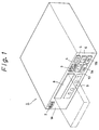
- Fig. 1 is a perspective view showing an overall construction of an embodiment of the invention
- Fig. 2 is a block diagram showing the construction of the embodiment of the invention
- Figs. 3 and 4 are schematic diagrams for explaining a TOC in the embodiment of the invention
- Figs. 5 and 6 are flow charts for explaining the embodiment of the invention
- Figs. 7 to 10 are schematic diagrams for explaining the embodiment of the invention.
- Fig. 1 is a perspective view showing an overall construction of an optical record and/or reproduction apparatus to which the invention has been applied.
- a display 9 is disposed on a front panel 1A of the optical record and/or reproduction apparatus 1.
- a power key 2 is disposed on the front panel 1A of the optical record and/or reproduction apparatus 1.
- an open/close key 3 is disposed on the front panel 1A of the optical record and/or reproduction apparatus 1.
- a power key 2 an open/close key 3, a reproduction key 4, a pause key 5, a stop key 6, music program select keys 7A and 7B, and a record key 10 are disposed on the front panel 1A of the optical record and/or reproduction apparatus 1.
- Reference numeral 8 denotes a disc tray which is pulled out of an opening of the front panel 1A.
- the disc tray 8 By operating the open/close key 3, the disc tray 8 is pulled out of the apparatus 1 as shown by alternate short and long dash lines. On the disc tray 8, an optical disc (not shown in the figure) is mounted. When the open/close key 3 is operated again, the disc tray 8 is pulled into the apparatus 1. The optical disc is loaded on a record and/or reproduction section in the apparatus 1.
- time information such as the total play time of the optical disc being loaded, the play time of a music program being reproduced, and the remaining play time of the music program being reproduced and the track number of the music program being reproduced are displayed.
- time information such as the total play time of the optical disc being loaded, the play time of a music program being reproduced, and the remaining play time of the music program being reproduced and the track number of the music program being reproduced are displayed.
- an optical disc on which a disc name and a track name have been recorded they are displayed on the display 9.
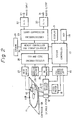
- Fig. 2 is a block diagram showing the construction of the optical disc record and/or reproduction apparatus to which the invention has been applied.
- reference numeral 11 denotes a disc cartridge.
- An optical disc 11B with a diameter of 64 mm is contained in a cartridge 11A.
- Pregrooves which were wobbled in the radial direction are provided in the optical disc 11B on the basis of address data. Recording of data onto the optical disc 11B or reading of data recorded on the optical disc 11B is performed on the basis of address data which was obtained by detecting the pregrooves. Record areas of the optical disc 11B have a first record area on which data based on information such as a general music program is recorded and a second record area on which content information such as a so-called TOC (Table of Contents) is recorded, which will be explained later. Record data corresponding to data, a plurality of programs and a plurality of music programs are recorded on the optical disc 11B along the pregrooves.
- TOC Table of Contents
- Reference numeral 12 denotes a spindle motor which rotates the optical disc 11B at a constant linear velocity.
- the spindle motor 12 is controlled by a servo control circuit 15 which will be described later.
- Reference numeral 13 shows a magnetic head which generates an external magnetic field.
- the magnetic head 13 applies a vertical magnetic field modulated according to data to be recorded onto the optical disc 11B.
- Reference numeral 14 denotes an optical pickup which irradiates a light beam onto the optical disc.
- the magnetic head 13 and the optical pickup 14 are opposed with the optical disc 11B therebetween.
- the magnetic head 13 and the optical pickup 14 are connected by a connecting mechanism (not shown) so that they are integrally moved in the radial direction of the optical disc 11B.
- Reference numeral 15 indicates a servo control circuit.
- the servo control circuit 15 generates error signals such as a focusing error signal and a tracking error signal corresponding to output signals received from the optical pickup 14 through an RF amplifier 29 which will be described later.
- the servo control circuit 15 supplies a control signal for performing focusing servo control and tracking servo control to the optical pickup 14 on the basis of error signals being generated.
- Reference numeral 16 denotes a feed motor which moves the optical pickup 14 in the radial direction of the optical disc 11B.
- the feed motor 16 moves the optical pickup 14 corresponding to a feed signal received from the servo control circuit 15 so as to perform a track jump operation.
- the feed motor 16 receives a low frequency component of the tracking error signal from the servo control circuit 15.
- Reference numeral 17 indicates a system controller which controls the operations of individual members of the apparatus.
- the system controller 17 is connected to a display 9 and an input key 18.
- the input key 18 is disposed on a front panel 1A shown in Fig. 1.
- the input key 18 includes the power key 2, the open/close key 3, the reproduction key 4, the pause key 5, the stop key 6, the music program select keys 7A and 7B, and the record key 10.
- the display 9 indicates content information of the optical disc 11B such as time information (for example, a total play time, a play time of a current music program or program, and a remaining time thereof), a track number of a current music program or program, a disc name, a track name, and so forth.
- Reference numeral 19 denotes a ROM (Read Only Memory).
- the ROM 19 stores time information corresponding to each cluster and each sector (which will be described later).
- the ROM 19 is connected to the system controller 17. Time information stored in the ROM 19 is read with data corresponding to a cluster number and a sector number obtained by the system controller 17, i.e., address data.
- Reference numeral 21 shows an input terminal.
- Reference numeral 22 denotes an A/D converter which converts an analog audio signal received from the input terminal 21 to a 16-bit digital signal.
- the sampling frequency of the A/D converter 22 is 44.1 kHz.
- Reference numeral 23 denotes a first sound compression encoder/decoder.
- the first encoder/decoder 23 compresses the amount of a digital signal received from the A/D converter 22 into approximately 1/5 times as small as that of the input signal.
- the first encoder/decoder 23 compresses and expands the amount of a signal by using modified DCT (Modified Discrete Cosine Transform) technique.
- modified DCT Modified Discrete Cosine Transform
- Reference numeral 24 denotes a memory controller which controls data write/read operations for a memory 25.
- the memory 25 is for example a dynamic RAM with a storage capacity of 1 Mbits.
- data received from the first encoder/decoder 23 is temporarily stored in the memory 25 through the memory controller 24.
- data received from a second encoder/decoder 26 is temporarily stored in the memory 25 through the memory controller 24.
- the second encoder/decoder 26 performs an error correction process for data read from the memory 25.
- the second encoder/decoder 26 performs an eight-to-fourteen modulation (EFM) for data which has been error-corrected with CIRC (Cross Interleave Reed Solomon Code).
- EFM eight-to-fourteen modulation
- Reference numeral 27 denotes a driving circuit which drives the magnetic head 13.
- the drive circuit 27 receives record data from the second encoder/decoder 26.
- Reference numeral 28 denotes an address decoder which decodes an address signal which has been recorded as the above-mentioned wobbled grooves based on a reproduced signal supplied from an RF amplifier 29.
- Reference numeral 30 denotes an D/A converter which converts a digital signal, which has been expanded by the first encoder/decoder 23, into an analog audio signal.
- the analog audio signal is outputted from an output terminal 31.
- a light beam which is in record level is irradiated from the optical pickup 14 to the optical disc 11B so as to heat up a record layer thereof (a magneto-optical layer in this embodiment).
- a vertical magnetic field corresponding to record data is applied to the opposite side of the optical disc 11.
- the magneto-optical record layer which is a record layer, is magnetized in the direction of the vertical magnetic field when the temperature of the magneto-optical recording layer is lowered as the light beam is moved.
- data is recorded on the optical disc 11B.
- a light beam with a power lower than that at the time of recording is irradiated to the optical disc 11B.
- the light beam is reflected by the magneto-optical record layer as an optical record layer of the optical disc 11B.
- the reflected light beam is detected by a pair of photodetectors of the optical pickup 14. By subtracting output signals of the pair of photodetectors, a reproduced signal of the optical disc 11B can be obtained.
- Data is recorded on the optical disc 11B cluster by cluster.
- One cluster is composed of 36 sectors.
- One sector (equivalent to one subcode block of a compact disc) is composed of 98 frames.
- the power of the light beam irradiated from the optical pickup 14 should be controlled.
- the length of the interleave of CIRC is 108 frames, which is longer than the length of one sector.
- a linking area is required between adjacent two clusters.
- the first three sectors of one cluster (36 sectors) are linking sectors.
- the next one sector is used for subdata.
- compressed data of one cluster (36 sectors) are recorded in 32 sectors.
- the position on the disc in the recording mode is designated by an address which has been recorded by wobbling grooves formed on the disc 11B.
- An address recorded as wobbled grooves is detected by the address decoder 28.
- the address detected by the address decoder 28 is supplied to the EFM and CIRC encoder/decoder 26.
- a record signal on the optical disc 11B is reproduced by the optical pickup 14.
- the reproduced signal is reproduced by the optical disc 11B cluster by cluster.
- the reproduced signal is sent to the EFM and CIRC encoder/decoder 26 through the RF amplifier 29.
- the EFM and CIRC encoder/decoder 26 performs EFM demodulation and error correction processes.
- An output of the EFM and CIRC encoder/decoder 26 is temporarily stored in the memory 25 through the memory controller 24.
- An output of the memory 25 is supplied to the sound compression encoder/decoder 23.
- the sound compression encoder/decoder 23 expands the amount of an audio signal.
- the sound compression encoder/decoder 23 When the sound compression encoder/decoder 23 receives data at 300 kbits/sec, it is possible to expand the compressed data and reproduce continuous sound.
- the optical pickup 14 reads a digital signal from the optical disc 11B at a transmission rate of 1.4 Mbits/sec.
- the memory 15 of 1 Mbits becomes full with a digital signal in approximately 0.9 seconds.
- a reproduced signal can be continuously outputted from the memory 25 for approximately three seconds at 300 kbits/sec.
- the optical pickup 14 can reaccess the original position of the optical disc 11B so as to read the record signal. Thus, a so-called sound jump can be prevented.
- Data which has been expanded by the sound compression encoder/decoder 23 is supplied to the D/A converter 30.
- the D/A converter 30 restores a digital signal to an analog signal.
- the resultant analog audio signal is outputted from the output terminal 31.
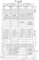
- a TOC is disposed on the innermost periphery of the optical disc 11B.
- the TOC stores information with respect to positions of data recorded on the optical disc 11B.
- Fig. 3 shows the construction of the TOC.
- the TOC is constructed of a header area and a data area.
- the header area starts with a fixed sync pattern area A1, followed by a header information area A2 which represents a cluster number and a sector number.
- the data area starts with a fixed pattern area A3.
- the pattern area A3 is followed by an identification information area A4 which includes a disc type information (for example, a reproduction-only-disc, a recordable disc, or a disc having a reproduction-only region and a recordable region), a record power, a last track number, a lead-out start address, the number of sectors being used, a power calibration start address, a user TOC start address, a start address of a recordable user area, and so forth.
- the identification information area A4 is followed by a track number point area A5 (P-TNO1, P-TNO2, P-TNO3, and so forth).
- the track number points are pointers which represent positions in the TOC with respect to information of the start address and end address of each track number.
- the track number point area A5 is followed by a track information area A6. Record positions in the TOC with respect to the information of the start address and end address of each track are recorded in the track information area A6.
- the record positions in the TOC with respect to the information of the start address and end address of each track are designated by the track number points (P-TNO1, P-TNO2, P-TNO3, and so forth).
- the optical disc 11B has a user TOC which is used to manage an audio signal being recorded.
- Fig. 4 shows the construction of the user TOC.
- the user TOC has information Link-P (denoted by B1) for each track information.
- the Link-P represents information of a track that follows. All the track information can be managed on the user TOC.
- the TOC information is stored in a part of the memory 25 when the disc is loaded in the apparatus.
- the user TOC is changed, it is changed in the memory 25.
- updated user TOC is recorded on the optical disc 11B.
- an audio signal received from the input terminal 21 is converted into a digital signal by the A/D converter 22.
- the digital signal is compressed by the first encoder/decoder 23.
- the compressed digital signal is temporarily stored in the memory 25.
- the second encoder/decoder 26 performs the error correction encoding and EFM modulating processes for the compressed digital signal.
- the resultant signal is recorded on the optical disc 11B by the optical pickup and the magnetic head 13.
- the optical pickup 14 and the magnetic head 13 are moved to a non-record area of the optical disc 11B based on the information of the user TOC so as to prevent audio data which has been recorded on the optical disc 11B from being erased. Then, recording of audio data is started from the non-record area of the optical disc 11B.
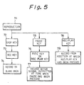
- Fig. 5 is a flow chart for explaining the above-described operation.
- the stop key is pressed (at step 72)
- audio data is being reproduced (at step 71)
- the reproducing operation is stopped.
- the record key 10 is pressed (at step 73) while the reproducing operation is being stopped, a blank area of the disc is detected from the TOC information and newly input audio data is recorded in the blank area of the disc (at step 74).
- a reproduction pause state takes place.
- the reproduction pause state when the record key 10 is pressed or both the record key 10 and the reproduction key 4 are pressed at the same time (at step 76), newly input audio data is recorded just after audio data which is being paused for reproduction (at step 77).
- both the reproduction key 4 and the record key 10 are pressed at the same time (at step 78), while audio data is being reproduced (at step 71), the reproducing operation of the audio data is stopped and newly input audio data is recorded after the position at which the reproducing operation of the audio data has been stopped (at step 79).
- the magnetic head 13 and the optical pickup 14 are moved to the start position of a first music program or a designated music program.
- the second encoder/decoder 26 performs EFM demodulating and error correcting processes for the audio data which is read from the disc 11B.
- the resultant data is expanded by the first encoder/decoder 23 and converted into an analog audio signal by the D/A converter 30.
- the analog audio signal is outputted from the output terminal 31.
- audio data is reproduced from the beginning of a first music program or a designated music program.
- the optical disc record and/or reproduction apparatus when the reproduction key 10 is pressed after a recording operation has been stopped, a reproducing operation is started from the beginning of the audio data which has been just recorded.
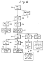
- Fig. 6 is a flow chart for explaining the above-described operation.
- a record state is set.
- the pause key 5 or the stop key 6 is pressed (at step 52 or 53) while the recording operation is being performed, the record state is stopped.
- the reproduction key 4 is pressed (at step 54)
- audio data which has been just recorded is reproduced from the beginning thereof (at step 55).
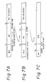
- Fig. 7 shows recording and reproducing states on the disc.
- the record key 10 is pressed at position T 1 and then the stop key 6 or the pause key 5 is pressed at position T 2 , an audio data stream M1 is recorded from the position T 1 to the position T 2 .
- the reproduction key 4 is pressed, a reproducing operation is started from the record start position T 1 as shown in Fig. 7B.
- the reproducing operation is paused. Thereafter, when the record key 10 is pressed or when both the record key 10 and the reproduction key 4 are pressed at the same time (at step 64), recording of next audio data is started from the pause position. In other words, next audio data is overwritten from the middle portion of the audio data which has been recorded (at step 65).
- both the record key 10 and the reproduction key 4 are pressed at the same time (at step 66) while a reproduction state is set at step 55, recording is started from the position where the keys have been pressed (at step 67).
- the record start position and record end position are obtained by reproducing track information of the TOC shown in Fig. 4.
- a blank area of the disc is accessed.
- an area between the positions T 11 and T 12 is a data area and other areas (before the position T 11 and after the position T 12 ) are blank areas
- the data area between the positions T 11 and T 12 is skipped so as to prevent the audio data recorded in the data area from being erased.
- an audio data stream music programs
- the positions of audio data which are continued are represented by the above-mentioned Link-P.
Landscapes
- Engineering & Computer Science (AREA)
- Multimedia (AREA)
- Signal Processing (AREA)
- Signal Processing For Digital Recording And Reproducing (AREA)
- Management Or Editing Of Information On Record Carriers (AREA)
- Indexing, Searching, Synchronizing, And The Amount Of Synchronization Travel Of Record Carriers (AREA)
Applications Claiming Priority (3)
| Application Number | Priority Date | Filing Date | Title |
|---|---|---|---|
| JP15741192 | 1992-05-25 | ||
| JP157411/92 | 1992-05-25 | ||
| EP93910367A EP0596139B1 (de) | 1992-05-25 | 1993-05-21 | Aufzeichnungs-/ wiedergabegerät für optische platten |
Related Parent Applications (2)
| Application Number | Title | Priority Date | Filing Date |
|---|---|---|---|
| EP93910367A Division EP0596139B1 (de) | 1992-05-25 | 1993-05-21 | Aufzeichnungs-/ wiedergabegerät für optische platten |
| EP93910367.7 Division | 1993-12-09 |
Publications (2)
| Publication Number | Publication Date |
|---|---|
| EP0798724A2 true EP0798724A2 (de) | 1997-10-01 |
| EP0798724A3 EP0798724A3 (de) | 1997-12-10 |
Family
ID=15649051
Family Applications (3)
| Application Number | Title | Priority Date | Filing Date |
|---|---|---|---|
| EP93910367A Expired - Lifetime EP0596139B1 (de) | 1992-05-25 | 1993-05-21 | Aufzeichnungs-/ wiedergabegerät für optische platten |
| EP97201754A Withdrawn EP0798724A3 (de) | 1992-05-25 | 1993-05-21 | Aufzeichnungs- und/oder Wiedergabegerät mit optischer Scheibe |
| EP97201772A Expired - Lifetime EP0795874B1 (de) | 1992-05-25 | 1993-05-21 | Optische Scheibe und/oder Wiedergabegerät |
Family Applications Before (1)
| Application Number | Title | Priority Date | Filing Date |
|---|---|---|---|
| EP93910367A Expired - Lifetime EP0596139B1 (de) | 1992-05-25 | 1993-05-21 | Aufzeichnungs-/ wiedergabegerät für optische platten |
Family Applications After (1)
| Application Number | Title | Priority Date | Filing Date |
|---|---|---|---|
| EP97201772A Expired - Lifetime EP0795874B1 (de) | 1992-05-25 | 1993-05-21 | Optische Scheibe und/oder Wiedergabegerät |
Country Status (6)
| Country | Link |
|---|---|
| EP (3) | EP0596139B1 (de) |
| JP (1) | JP3531165B2 (de) |
| KR (1) | KR100306096B1 (de) |
| DE (2) | DE69323034T2 (de) |
| TW (1) | TW258810B (de) |
| WO (1) | WO1993024929A1 (de) |
Families Citing this family (4)
| Publication number | Priority date | Publication date | Assignee | Title |
|---|---|---|---|---|
| JP3130380B2 (ja) * | 1992-08-28 | 2001-01-31 | 株式会社ケンウッド | 光ディスク記録再生装置 |
| KR100223186B1 (ko) * | 1997-01-29 | 1999-10-15 | 윤종용 | Dvd-ram에서 고속의 데이타기록방법 |
| JP3873523B2 (ja) * | 1999-05-21 | 2007-01-24 | ソニー株式会社 | 再生装置 |
| EP1085767B1 (de) * | 1999-09-20 | 2011-08-10 | Panasonic Corporation | Eine Kodier-/Aufnahme-Vorrichtung, die die Kodierung von Videodaten und die Bemusterung von einem Tonsignal unterbricht, als Antwort auf einen Aufnahmepauseauftrag, um die ununterbrochene Wiedergabe von vor und nach der Aufnahmepause aufgenommemen Daten zu ermöglichen |
Citations (6)
| Publication number | Priority date | Publication date | Assignee | Title |
|---|---|---|---|---|
| JPS6050786A (ja) * | 1983-08-31 | 1985-03-20 | Toyota Motor Corp | 車両用dadプレ−ヤの操作方法 |
| EP0275972A1 (de) * | 1987-01-19 | 1988-07-27 | Sony Corporation | Vorrichtung zur Aufzeichnung auf Platten |
| EP0292917A1 (de) * | 1987-05-25 | 1988-11-30 | Sony Corporation | Gerät zur Informationsaufzeichnung und/oder Wiedergabe auf eine optische Platte oder von einer optischen Platte |
| EP0346979A2 (de) * | 1988-06-15 | 1989-12-20 | Koninklijke Philips Electronics N.V. | Wiedergabe- und/oder Aufzeichnungsgerät |
| JPH0352182A (ja) * | 1989-07-20 | 1991-03-06 | Canon Inc | 記録再生装置 |
| EP0474377A1 (de) * | 1990-08-24 | 1992-03-11 | Sony Corporation | Aufzeichnungsgerät für optische Platten |
Family Cites Families (7)
| Publication number | Priority date | Publication date | Assignee | Title |
|---|---|---|---|---|
| JPS61224187A (ja) * | 1985-03-29 | 1986-10-04 | Sony Corp | デイスク記録装置 |
| CA1306804C (en) * | 1987-03-05 | 1992-08-25 | Ryo Ando | Method and apparatus for recording and/or reproducing to and from disk |
| JPH02179982A (ja) * | 1988-12-29 | 1990-07-12 | Sharp Corp | ディスク記録再生装置 |
| JPH02187979A (ja) * | 1989-01-13 | 1990-07-24 | Sharp Corp | ディスク記録再生装置 |
| CA2020059C (en) * | 1989-06-30 | 1995-05-23 | Shigemi Maeda | Modular ceramic igniter |
| JP3158556B2 (ja) * | 1991-09-27 | 2001-04-23 | ソニー株式会社 | ディスク記録装置及びディスク再生装置 |
| US6438083B1 (en) * | 1991-11-19 | 2002-08-20 | Koninklijke Philips Electronics N.V. | Apparatus for recording a continuous information stream in available gaps between pre-recorded portions of a recording track, record carrier so recorded, and apparatus for reading such record carrier |
-
1993
- 1993-04-19 TW TW082102976A patent/TW258810B/zh not_active IP Right Cessation
- 1993-05-21 EP EP93910367A patent/EP0596139B1/de not_active Expired - Lifetime
- 1993-05-21 WO PCT/JP1993/000668 patent/WO1993024929A1/ja active IP Right Grant
- 1993-05-21 DE DE69323034T patent/DE69323034T2/de not_active Expired - Lifetime
- 1993-05-21 JP JP50038794A patent/JP3531165B2/ja not_active Expired - Lifetime
- 1993-05-21 EP EP97201754A patent/EP0798724A3/de not_active Withdrawn
- 1993-05-21 DE DE69330688T patent/DE69330688T2/de not_active Expired - Lifetime
- 1993-05-21 EP EP97201772A patent/EP0795874B1/de not_active Expired - Lifetime
- 1993-05-21 KR KR1019940700223A patent/KR100306096B1/ko not_active IP Right Cessation
Patent Citations (6)
| Publication number | Priority date | Publication date | Assignee | Title |
|---|---|---|---|---|
| JPS6050786A (ja) * | 1983-08-31 | 1985-03-20 | Toyota Motor Corp | 車両用dadプレ−ヤの操作方法 |
| EP0275972A1 (de) * | 1987-01-19 | 1988-07-27 | Sony Corporation | Vorrichtung zur Aufzeichnung auf Platten |
| EP0292917A1 (de) * | 1987-05-25 | 1988-11-30 | Sony Corporation | Gerät zur Informationsaufzeichnung und/oder Wiedergabe auf eine optische Platte oder von einer optischen Platte |
| EP0346979A2 (de) * | 1988-06-15 | 1989-12-20 | Koninklijke Philips Electronics N.V. | Wiedergabe- und/oder Aufzeichnungsgerät |
| JPH0352182A (ja) * | 1989-07-20 | 1991-03-06 | Canon Inc | 記録再生装置 |
| EP0474377A1 (de) * | 1990-08-24 | 1992-03-11 | Sony Corporation | Aufzeichnungsgerät für optische Platten |
Non-Patent Citations (2)
| Title |
|---|
| PATENT ABSTRACTS OF JAPAN vol. 009, no. 177 (P-375), 23 July 1985 & JP 60 050786 A (TOYOTA JIDOSHA KK), 20 March 1985, * |
| PATENT ABSTRACTS OF JAPAN vol. 015, no. 205 (P-1206), 27 May 1991 & JP 03 052182 A (CANON INC), 6 March 1991, * |
Also Published As
| Publication number | Publication date |
|---|---|
| EP0596139A1 (de) | 1994-05-11 |
| DE69323034T2 (de) | 1999-08-19 |
| DE69323034D1 (de) | 1999-02-25 |
| DE69330688T2 (de) | 2002-06-13 |
| KR100306096B1 (ko) | 2001-12-01 |
| EP0596139A4 (de) | 1995-12-20 |
| EP0795874A2 (de) | 1997-09-17 |
| EP0795874B1 (de) | 2001-08-29 |
| JP3531165B2 (ja) | 2004-05-24 |
| EP0596139B1 (de) | 1999-01-13 |
| DE69330688D1 (de) | 2001-10-04 |
| WO1993024929A1 (en) | 1993-12-09 |
| EP0795874A3 (de) | 1997-12-10 |
| EP0798724A3 (de) | 1997-12-10 |
| TW258810B (de) | 1995-10-01 |
Similar Documents
| Publication | Publication Date | Title |
|---|---|---|
| EP0310678B1 (de) | Plattenaufzeichnungs-/wiedergabegerät und plattenaufzeichnungs-/wiedergabemethode | |
| JP3199082B2 (ja) | オーディオデータの区切り位置調整方法および装置 | |
| JP2001052437A (ja) | ディスク記録装置 | |
| KR100255345B1 (ko) | 기록매체의 재생방법과 그 장치 | |
| US5453967A (en) | Disc reproducing apparatus which stops recording in response to compressed data stored, in a record stop state, in a memory | |
| US5553055A (en) | Disc playback method | |
| US5633841A (en) | Optical disc recording/reproducing apparatus having automatic protection of previously recorded data | |
| EP0571123B1 (de) | Anzeige für Plattenwiedergabe | |
| CA2084722C (en) | Information recording and reproduction apparatus | |
| EP0795874B1 (de) | Optische Scheibe und/oder Wiedergabegerät | |
| JP3360873B2 (ja) | ディスク記録装置及び方法 | |
| US5859815A (en) | Apparatus and methods for minimizing non-recordable areas and numbers of parts per track on a digital recording medium | |
| JP3281899B2 (ja) | ミニディスクレコーダ | |
| JP3482961B2 (ja) | ディスク記録再生方法 | |
| JP2887189B2 (ja) | 情報記録再生装置 | |
| JPH05325515A (ja) | ディスク再生装置 | |
| JP3362897B2 (ja) | 再生装置 | |
| JPH05325508A (ja) | ディスク記録再生装置 | |
| JP3276803B2 (ja) | ディスク記録再生装置 | |
| JPH06231538A (ja) | ディスク記録再生装置 | |
| JPH0676483A (ja) | ディスク記録装置 | |
| JP2004327035A (ja) | ディスク記録装置及びディスク記録方法 | |
| JPH06309788A (ja) | 情報記録再生装置 | |
| JPH08102170A (ja) | ディスク担体記録再生装置 | |
| JP2002358723A (ja) | 記録装置及びディスク記録方法 |
Legal Events
| Date | Code | Title | Description |
|---|---|---|---|
| PUAI | Public reference made under article 153(3) epc to a published international application that has entered the european phase |
Free format text: ORIGINAL CODE: 0009012 |
|
| AC | Divisional application: reference to earlier application |
Ref document number: 596139 Country of ref document: EP |
|
| AK | Designated contracting states |
Kind code of ref document: A2 Designated state(s): DE FR GB |
|
| PUAL | Search report despatched |
Free format text: ORIGINAL CODE: 0009013 |
|
| RHK1 | Main classification (correction) |
Ipc: G11B 27/10 |
|
| AK | Designated contracting states |
Kind code of ref document: A3 Designated state(s): DE FR GB |
|
| 17P | Request for examination filed |
Effective date: 19980428 |
|
| RBV | Designated contracting states (corrected) |
Designated state(s): DE FR GB |
|
| 17Q | First examination report despatched |
Effective date: 20000321 |
|
| STAA | Information on the status of an ep patent application or granted ep patent |
Free format text: STATUS: THE APPLICATION IS DEEMED TO BE WITHDRAWN |
|
| 18D | Application deemed to be withdrawn |
Effective date: 20000801 |