EP0797293B1 - Procédé pour corriger des non-linéarités d'un amplificateur et émetteur radio mettant en oeuvre un tel procédé - Google Patents
Procédé pour corriger des non-linéarités d'un amplificateur et émetteur radio mettant en oeuvre un tel procédé Download PDFInfo
- Publication number
- EP0797293B1 EP0797293B1 EP97400613A EP97400613A EP0797293B1 EP 0797293 B1 EP0797293 B1 EP 0797293B1 EP 97400613 A EP97400613 A EP 97400613A EP 97400613 A EP97400613 A EP 97400613A EP 0797293 B1 EP0797293 B1 EP 0797293B1
- Authority
- EP
- European Patent Office
- Prior art keywords
- signal
- adaptation
- predistortion
- complex
- adaptation period
- Prior art date
- Legal status (The legal status is an assumption and is not a legal conclusion. Google has not performed a legal analysis and makes no representation as to the accuracy of the status listed.)
- Expired - Lifetime
Links
Images


Classifications
-
- H—ELECTRICITY
- H04—ELECTRIC COMMUNICATION TECHNIQUE
- H04L—TRANSMISSION OF DIGITAL INFORMATION, e.g. TELEGRAPHIC COMMUNICATION
- H04L27/00—Modulated-carrier systems
- H04L27/32—Carrier systems characterised by combinations of two or more of the types covered by groups H04L27/02, H04L27/10, H04L27/18 or H04L27/26
- H04L27/34—Amplitude- and phase-modulated carrier systems, e.g. quadrature-amplitude modulated carrier systems
- H04L27/36—Modulator circuits; Transmitter circuits
- H04L27/366—Arrangements for compensating undesirable properties of the transmission path between the modulator and the demodulator
- H04L27/367—Arrangements for compensating undesirable properties of the transmission path between the modulator and the demodulator using predistortion
- H04L27/368—Arrangements for compensating undesirable properties of the transmission path between the modulator and the demodulator using predistortion adaptive predistortion
-
- H—ELECTRICITY
- H03—ELECTRONIC CIRCUITRY
- H03F—AMPLIFIERS
- H03F1/00—Details of amplifiers with only discharge tubes, only semiconductor devices or only unspecified devices as amplifying elements
- H03F1/32—Modifications of amplifiers to reduce non-linear distortion
- H03F1/3241—Modifications of amplifiers to reduce non-linear distortion using predistortion circuits
- H03F1/3247—Modifications of amplifiers to reduce non-linear distortion using predistortion circuits using feedback acting on predistortion circuits
-
- H—ELECTRICITY
- H03—ELECTRONIC CIRCUITRY
- H03F—AMPLIFIERS
- H03F1/00—Details of amplifiers with only discharge tubes, only semiconductor devices or only unspecified devices as amplifying elements
- H03F1/32—Modifications of amplifiers to reduce non-linear distortion
- H03F1/3241—Modifications of amplifiers to reduce non-linear distortion using predistortion circuits
- H03F1/3282—Acting on the phase and the amplitude of the input signal
-
- H—ELECTRICITY
- H03—ELECTRONIC CIRCUITRY
- H03F—AMPLIFIERS
- H03F2200/00—Indexing scheme relating to amplifiers
- H03F2200/438—Separate feedback of amplitude and phase signals being present
-
- H—ELECTRICITY
- H03—ELECTRONIC CIRCUITRY
- H03F—AMPLIFIERS
- H03F2201/00—Indexing scheme relating to details of amplifiers with only discharge tubes, only semiconductor devices or only unspecified devices as amplifying elements covered by H03F1/00
- H03F2201/32—Indexing scheme relating to modifications of amplifiers to reduce non-linear distortion
- H03F2201/3233—Adaptive predistortion using lookup table, e.g. memory, RAM, ROM, LUT, to generate the predistortion
Definitions
- the present invention relates to a method for correcting non-linearities of a radio power amplifier.
- the invention finds applications in transmitters radio, especially mobile radio stations.
- Digital mobile radio systems use radio modulations more and more often non-constant envelope to improve spectral efficiency of the system.
- These non-constant envelope modulations include in particular phase shift modulations in quadrature (QPSK, OQPSK or ⁇ / 4-QPSK), or modulations by displacement of amplitude and phase in quadrature (n-QAM modulations).
- the predistortion linearization technique adaptive is an amplifier linearization technique usable for this purpose. This technique is described in the article "Adaptive Linearisation Using Predistorsion" by M. Faulkner et al (Proc. Of the 40th IEEE Veh. Tech. Conf. 1990, pages 35-40), and in US Patent 5,093,637.
- the technique of linearization by adaptive predistortion consists in apply a predistortion table to the complex band signal basic . This table is calculated numerically by comparing the baseband signal and a demodulated signal obtained from the amplified radio signal. This calculation consists in modifying the table of predistortion in order to obtain a table correcting the distortions in the broadcast chain. After a period initial adaptation, the predistortion table corrects the amplifier non-linearities.
- the predistortion algorithms used are generally based on the assumption that the distortion introduced by the power amplifier depends only on the module of the complex signal in baseband and not of its phase (distortions AM-AM and AM-PM only). Consequently, we choose predistortion functions which depend only on the module of the signal.
- some distortions can also be introduced by the modulator used to transpose the signal around the carrier frequency, as well as by the demodulator producing the demodulated signal useful in periods adaptation.
- the modulator and the demodulator can have balance and / or quadrature faults which, in addition to the PM-AM and PM-PM distortions that they introduce risk of converge the adaptation algorithm to a table of inadequate predistortion.
- An object of the present invention is to improve the linearization process by adaptive predistortion in making it less susceptible to faults in the modulator or demodulator.
- the invention thus provides a method for correcting non-linearities of an amplifier receiving a radio signal and producing an amplified radio signal representative of a signal complex digital input, in which a table is stored predistortion associating a value of a digital signal complex predistorted at each value of the complex signal input, and we modulate the predistorted complex signal for obtain the radio signal addressed to the amplifier.
- a fraction of the radio signal is demodulated amplified to obtain a complex demodulated signal which is compared the complex input signal with which the signal is associated predistorted complex modulated in said adaptation period to update the predistortion table.
- the complex input signal or the predistorted complex signal has a constant phase modulo ⁇ in the period adaptation.
- phase of the complex signal the argument ⁇ of the complex number I + jQ.
- the complex input signal has a spectrum narrower during the adjustment period than outside the adjustment period. This undesirable emissions outside the allocated bandwidth, in the periods adaptation during which the adaptation algorithm of tables has not yet converged.
- a radio transmitter comprising: a digital signal source generating a complex digital input signal; ways to predistortion producing a complex predistorted digital signal based on the complex input signal and a table of predistortion; modulation means producing a signal radio from the predistorted complex signal; an amplifier of power to amplify the radio signal and apply it to a transmitting antenna; and demodulation means producing a complex signal demodulated from a fraction of the radio signal amplified.
- the predistortion means are arranged to put update the predistortion table based on a comparison between the demodulated complex signal produced by the means of demodulation in at least one adaptation period and the signal input complex with which the complex signal is associated predistorted product in said adaptation period by the means of predistortion.
- the means of predistortion are arranged to use a signal during the adaptation period input complex having a constant phase modulo ⁇ , or for generate a complex signal during the adaptation period predistorted having a constant phase modulo ⁇ .
- the radio transmitter shown in Figure 1 is for example part of a digital mobile radio station.
- Reference 10 designates a digital signal source producing a complex input signal m in the form of a phase component I m and a quadrature component Q m at a sampling frequency F s .
- a predistortion unit 12 applies a predistortion to the input signal m to produce a complex predistorted digital signal d having a phase component I d and a quadrature component Q d .
- This predistorted signal is converted to analog by a digital-analog converter 14, then supplied to a quadrature modulator 16.
- the power amplifier 20 amplifies the radio signal d 'and supplies the amplified radio signal to the antenna 22 of the transmitter.
- a coupler 24 takes a fraction r 'of the amplified radio signal at the output of amplifier 20. This fraction r' is supplied to a quadrature demodulator 26 which, using the cos ⁇ t and -sin ⁇ t waves from the local oscillator , produces a complex demodulated signal r.
- the phase I r and quadrature components Q r of the demodulated signal are digitized by an analog-digital converter 28 at the sampling frequency F s , on the same number of bits as the components of the input signal m (for example 12 bits).
- FIG. 2 shows a block diagram of the digital signal source 10.
- the reference 30 designates the binary information source of the transmitter, which delivers information bits a 0 , a 1 , ... coded and set forms according to the formats specific to the radio system adopted.
- a logic unit 32 codes the information bits to produce components coded in phase I i and in quadrature Q i at a rate half that of the information bits in accordance with the type of modulation used. This modulation has a non-constant envelope. In the example considered, it is a differential modulation by phase displacement in quadrature with phase jumps of ⁇ ⁇ / 4 or ⁇ 3 ⁇ / 4 (modulation ⁇ / 4-DQPSK).
- the components I i and Q i of the sample i of the coded complex signal are then respectively of the form cos ⁇ i and sin ⁇ i , the phase jump ⁇ i + 1 - ⁇ i depending on the values of the two information bits successive a 2i , a 2i + 1 as indicated in table I.
- the sampling frequency F s is greater than the rate of the information bits. For example, if the information bits a 2i , a 2i + 1 have a rate of 36 kbit / s, the complex samples I i , Q i are at a rate of 18 kbit / s, and we can oversample them in a factor 8 to have a sampling frequency F s of 144 kHz.
- the components I i and Q i are each shaped by a filter 34 of the half-Nyquist type adapted to the oversampling frequency F s . This produces the baseband input signal m having a spectrum confined in a bandwidth of 18 kHz.
- FIG. 3 shows the shape of the spectrum of the radio signal ⁇ / 4-DQPSK amplified linearly (curve A) and amplified with a non-linear amplifier with high efficiency (curve B).
- curve A the shape of the spectrum of the radio signal ⁇ / 4-DQPSK amplified linearly
- curve B the shape of the spectrum of the radio signal ⁇ / 4-DQPSK amplified linearly
- curve B the shape of the spectrum due to non-linearities is not acceptable. This is the reason why the predistortion unit 12 is provided, the role of which is to compensate for the non-linearities of the power amplifier 20.
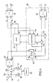
- FIG. 4 shows an exemplary embodiment of the predistortion unit 12.
- the distortions introduced by the amplifier 20 being assumed to be of the AM-AM and AM-PM type, the predistortion is applied in polar coordinates ⁇ , ⁇ and not in Cartesian coordinates I, Q.
- Three arithmetic units 40, 42, 44 are thus provided for respectively converting polar coordinates ⁇ m, m ⁇ the input signal m, converting polar coordinates ⁇ r, r ⁇ the demodulated signal r, and converting Cartesian coordinates of I, Q of the signal predistorted d calculated in polar coordinates ⁇ d, ⁇ d.
- the module ⁇ m of the input signal serves as an address pointer in a random access memory (RAM) 46 where a predistortion table is stored associating with each quantized value of ⁇ m a value of the module ⁇ d of the predistorted signal, and a phase shift value ⁇ to apply to pre-distort the signal.
- the addressing in the memory 46 can be carried out using log 2 K most significant bits of ⁇ m , for example the 5 most significant bits for a table.
- predistortion at K 32 inputs, the stored values ⁇ d , ⁇ can be quantized over 12 bits.
- a summator 48 adds the phase shift ⁇ to the phase ⁇ m of the input signal to produce the phase ⁇ d of the predistorted signal.
- the values contained in the predistortion table are calculated adaptively.
- the complex input signal m is not that delivered by the filters 34, but an adaptation signal particular.
- These adaptation periods are dedicated to linearization of the amplifier and not the transmission of a useful signal.
- adaptation periods can be planned initial corresponding to time intervals of 238 bits (either 952 complex samples or ⁇ 6.6 ms) dedicated to the convergence of the predistortion algorithm and, at the beginning of each transmission time interval, one period 32-bit adaptation (i.e. 128 complex samples or ⁇ 0.89 ms) dedicated to the cooling of the table predistortion.
- the demodulated signal r collected during the adaptation periods is compared with the adaptation signal to update the predistortion table.
- the adaptation signal expressed in polar coordinates ⁇ 0 , ⁇ 0 is delayed by a filter 50 by a preset time to compensate for the delay that the signal r undergoes when crossing the radio channel.
- the delayed signal m ' can thus be compared, by means of subtractors 52, 54, to the demodulated signal r which corresponds to it.
- the reference 58 designates the numerical means used for updating the predistortion table, namely the arithmetic unit 42, the filter 50, the subtractors 52, 54 and the adaptation unit 56.
- the reference 60 designates an ideal quadrature modulator with two multipliers 62, 64 respectively modulating the cos ⁇ t wave by the phase I 'component present at the input, and the -sin ⁇ t wave by the quadrature component Q', and a summator 66 delivering the modulated signal from the outputs of multipliers 62, 64 (of course, the modulation can also be carried out by passing through one or more intermediate frequencies).
- a balance defect results in the fact that the components I and Q undergo different gains in the modulator, which is represented by the multipliers 72 and 74 respectively applying gains 1 + a and 1 - a components in phase and in quadrature (a ⁇ 0 creates a balance defect).
- a quadrature defect would correspond to the fact that the two waves coming from the local oscillator would not be exactly in quadrature.
- a quadrature fault corresponds to a non-zero angle ⁇
- Q ' I. 1 + a .sin ⁇ + Q. 1 - a .cos ⁇ at the input of an ideal modulator 60.
- the module is deformed depending on the phase to input (PM-AM distortion), and the phase at the output depends from the phase to the input in a non-linear way (PM-PM distortion).
- PM-AM distortion phase to input
- PM-PM distortion phase at the output depends from the phase to the input in a non-linear way
- balance and quadrature faults are relatively small (a and ⁇ small), so that the PM-AM and PM-PM distortions cause only a small spectrum disturbance. If these distortions can remain acceptable with regard to broadening the spectrum that they cause directly outside the periods of adaptation, the inventors have found that they degraded performance, further causing convergence of the predistortion table towards values inadequate.
- the predistortion unit 12 introduces a certain fluctuation ⁇ into the phase ⁇ d of the predistorted signal applied to the modulator 16 when the phase ⁇ 0 of the adaptation signal is constant.
- this fluctuation remains of small amplitude since it corresponds approximately to the phase distortions due to the non-linearities of the amplifier 20, which are typically less than 10 °. Consequently, this fluctuation ⁇ does not disturb the convergence too much, in any case much less than if we let the phase ⁇ 0 vary with an amplitude of the order of ⁇ .
- phase fluctuation ⁇ is moreover compensated by the non-linearity of the amplifier 20 in the input signal r 'of the demodulator 26, so that the PM-AM and PM-PM distortions induced by the demodulator remain approximately constant during adaptation and do not disturb convergence.
- Figure 6 shows the spectrum of an amplified radio signal obtained (apart from adaptation periods) using an adaptation signal constant phase (curve C) and an adaptation signal to variable phase of the same nature as the input signal m generated outside the adaptation periods (curve D).
- Curve C an adaptation signal constant phase
- curve D an adaptation signal to variable phase of the same nature as the input signal m generated outside the adaptation periods
- the modulo ⁇ constant phase adaptation signal is generated using a memory 80 of the PROM type in which the successive samples of a function are read at the rate F s x 0 (t).
- Two multipliers 82, 84 multiply the output x 0 of memory 80 by constants c 0 and s 0 to respectively produce the components in phase I 0 and in quadrature Q 0 of the adaptation signal.
- Two switches 86, 88 are controlled by the transmission controller of the terminal in order to address the components I m , Q m coming from the digital signal source 10 outside the adaptation periods at the input of the arithmetic unit 40. position 0), and the components I 0 , Q 0 of the adaptation signal during the adaptation periods (position 1).
- the values of the function x 0 (t) stored in the memory 80 are chosen so as to present a distribution capable of exploring the desired dynamic range of the amplifier 20.
- the matching signal exhibits both constant phase and narrow band properties, the advantages of which have been presented above.
- a convenient way of achieving this consists in providing an adaptation signal whose real and imaginary parts are proportional to the same sinusoidal waveform of frequency f 0 substantially less than a quarter of the bit rate of the binary information source 30.
- the spectrum of the adaptation signal is then reduced to two lines spaced by 2f 0 .
- f 0 4.5 kHz.
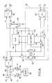
- the variant embodiment of the unit of predistortion 12 shown in Figure 8 differs from that of FIG. 4 in that the phase kept constant modulo ⁇ is not that of the adaptation signal, but that of the predistorted adaptation signal.
- the phase being then constant (modulo ⁇ ) at the input of modulator 16, the convergence of the adaptation algorithm is not disturbed by balance and quadrature faults of the demodulator (relations (1) and (2)), independently of the predistortions of phase ⁇ contained in the predistortion table.
- the AM-PM distortion due to the non-linearities of the amplifier 20 causes a fluctuation of the order of ⁇ (generally weak) at the input of the demodulator 26.
- a switch 90 is added in order to transmit to the adder 48 the phase predistortion ⁇ read in the memory 46 only outside the adaptation periods (position 0). In the adaptation periods, the switch 90 addresses a zero value to the adder 48 (position 1), which ensures that the phase of the predistorted signal corresponds to the constant phase modulo ⁇ delivered by the arithmetic unit 40.
- a subtractor calculates the difference between the phase ⁇ m delivered by the arithmetic unit 40 and the phase predistortion ⁇ read in the memory 46. This difference represents the phase ⁇ 0 of the adaptation signal, and is supplied to the updating means 58 so that after the ad hoc delay, it is compared with the phase ⁇ r of the demodulated signal.
- FIG. 9 shows an advantageous alternative embodiment 158 of the updating means 58 of a predistortion unit according to FIG. 4 or FIG. 8.
- Two buffer memories 100, 200 are provided for storing N successive complex samples of the signal adaptation and the demodulated signal in the adaptation periods.
- the number N is typically chosen equal to the number of samples at the frequency F s of the adaptation signal in the adaptation period.
- the memory 100 receives the polar coordinates ⁇ 0 , ⁇ 0 of the adaptation signal, while the memory 200 receives the Cartesian coordinates I r , Q r of the demodulated signal r.
- the processing operations for updating the predistortion table are carried out after the reception of the two blocks of N samples of the adaptation signal and of the demodulated signal.
- the first of these treatments, operated by the unit 151, consists in correcting a zero offset that the demodulated signal r can have.
- the adaptation signal being at zero mean, it is normally the same for the demodulated signal. However, faults of the modulator 16 and / or of the demodulator 26 can cause an offset of zero (offset) in the demodulated signal.
- I r (i) and Q r (i) denote the i-th stored samples of the in-phase and quadrature components of the demodulated complex signal r
- I s (i) and Q s (i) denote the i-th samples of the in-phase and quadrature components of a corrected demodulated signal s that the correction unit 151 supplies to the arithmetic unit 142.
- the unit 142 produces the module ⁇ s and the phase ⁇ s of the corrected demodulated signal s.
- c d denotes a damping coefficient between 0 and 1
- L denotes a block length for estimating the delay (L ⁇ N, typically L ⁇ 100)
- ⁇ s (i) denotes the i-th sample of the module of the corrected demodulated signal
- ⁇ m ' (i) denotes the i-th sample of the module of the delayed adaptation signal.
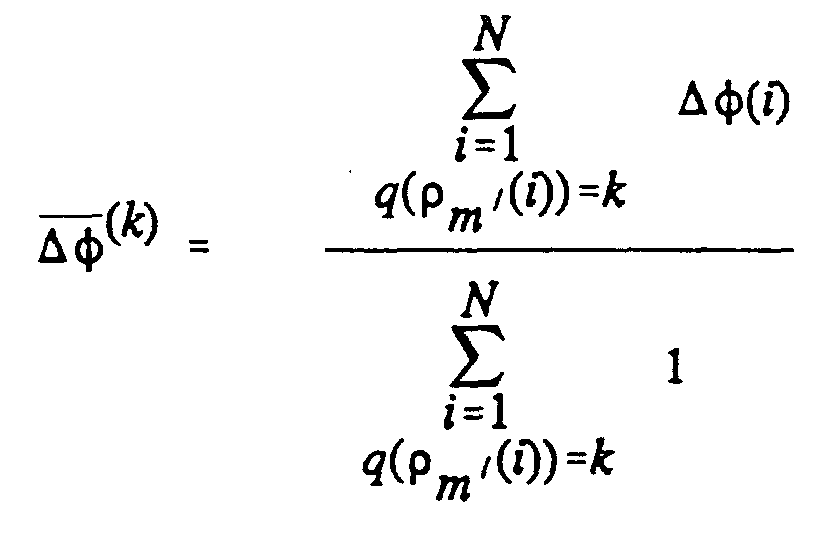
- unit 155 calculates the means ⁇ (k) and ⁇ (k) deviations ⁇ (i) and ⁇ (i) delivered by the subtractors 152, 154 for which the modulus ⁇ m ' of the adaptation signal is quantified by the index k:
- the values stored at the K addresses of the predistortion table are thus updated at the end of the processing of a block of N samples.
- the taking into account of average values ⁇ (k) and ⁇ (k) in relations (5) and (6) allows, compared to the use of relations (1) and (2) without averaging, to reduce errors due to faults in the modulator and / or the demodulator (balance or quadrature) and inter-sample interference, and also reduce the influence of noise present in the demodulated signal.
- the averaging also allows the predistortion algorithm to converge faster.
- Block processing also has the advantages of measuring and eliminating the zero offset of the demodulated signal (unit 151), and of allowing a fine estimate of the delay D to be applied to the adaptation signal.
Landscapes
- Engineering & Computer Science (AREA)
- Physics & Mathematics (AREA)
- Nonlinear Science (AREA)
- Power Engineering (AREA)
- Computer Networks & Wireless Communication (AREA)
- Signal Processing (AREA)
- Amplifiers (AREA)
- Transmitters (AREA)
- Digital Transmission Methods That Use Modulated Carrier Waves (AREA)
Description
- la figure 1 est un schéma synoptique d'un émetteur radio adapté à la mise en oeuvre de la présente invention ;
- la figure 2 est un schéma synoptique d'une source de signal numérique de l'émetteur de la figure 1 ;
- la figure 3 est un graphique montrant l'effet des non-linéarités d'un amplificateur sur le spectre d'un signal radio ;
- la figure 4 est un schéma synoptique d'une unité de prédistorsion de l'émetteur de la figure 1 ;
- la figure 5 est un schéma de principe d'un modulateur radio en quadrature ;
- la figure 6 est un graphique montrant l'amélioration procurée par l'utilisation d'un signal d'adaptation à phase constante sur le spectre du signal linéarisé ;
- la figure 7 est un graphique montrant le spectre du signal émis pendant les phases d'adaptation lorsqu'on utilise un signal d'adaptation à bande étroite ;
- la figure 8 montre une variante de réalisation d'une unité de prédistorsion ; et
- la figure 9 est un schéma synoptique de moyens de mise à jour d'une table de prédistorsion.
| a2i | a2i+1 | i+1-i |
| 0 | 0 | +π/4 |
| 0 | 1 | +3π/4 |
| 1 | 0 | -π/4 |
| 1 | 1 | -3π/4 |


Claims (8)
- Procédé pour corriger des non-linéarités d'un amplificateur (20) recevant un signal radio (d') et produisant un signal radio amplifié représentatif d'un signal numérique complexe d'entrée (m), dans lequel on mémorise une table de prédistorsion associant une valeur d'un signal numérique complexe prédistordu à chaque valeur du signal numérique complexe d'entrée, et on module le signal complexe prédistordu (d) pour obtenir le signal radio adressé à l'amplificateur, le procédé comportant au moins une période d'adaptation dans laquelle on démodule une fraction (r') du signal radio amplifié pour obtenir un signal complexe démodulé (r) qu'on compare au signal complexe d'entrée auquel est associé le signal complexe prédistordu modulé dans ladite période d'adaptation pour mettre à jour la table de prédistorsion, caractérisé en ce que le signal complexe d'entrée ou le signal complexe prédistordu possède une phase constante modulo π dans la période d'adaptation.
- Procédé selon la revendication 1, caractérisé en ce que le signal complexe d'entrée a un spectre plus étroit dans la période d'adaptation qu'en dehors de la période d'adaptation.
- Procédé selon la revendication 1 ou 2, caractérisé en ce que, dans la période d'adaptation, le signal complexe d'entrée a des parties réelle et imaginaire proportionnelles à une même forme d'onde sinusoïdale.
- Procédé selon l'une quelconque des revendications 1 à 3, caractérisé en ce que, dans la période d'adaptation, le signal complexe d'entrée ou le signal complexe prédistordu a des parties réelle et imaginaire identiques.
- Emetteur radio, comprenant : une source de signal numérique (10) générant un signal numérique complexe d'entrée (m) ; des moyens de prédistorsion (12) comportant une table de prédistorsion associant une valeur d'un signal numérique complexe prédistordu à chaque valeur du signal numérique complexe d'entrée ; des moyens de modulation (16) produisant un signal radio (d') à partir du signal complexe prédistordu (d) ; un amplificateur de puissance (20) pour amplifier le signal radio et l'appliquer à une antenne d'émission (22) ; et des moyens de démodulation (26) produisant un signal complexe démodulé (r) à partir d'une fraction (r') du signal radio amplifié, dans lequel les moyens de prédistorsion (12) sont agencés pour mettre à jour la table de prédistorsion sur la base d'une comparaison entre le signal complexe démodulé produit par les moyens de démodulation dans au moins une période d'adaptation et le signal complexe d'entrée auquel est associé le signal complexe prédistordu produit dans ladite période d'adaptation par les moyens de prédistorsion, caractérisé en ce que les moyens de prédistorsion (12) sont agencés pour utiliser dans la période d'adaptation un signal complexe d'entrée ayant une phase constante modulo π, ou pour générer dans la période d'adaptation un signal complexe prédistordu ayant une phase constante modulo π.
- Emetteur radio selon la revendication 5, caractérisé en ce que le signal complexe d'entrée a un spectre plus étroit dans la période d'adaptation qu'en dehors de la période d'adaptation.
- Emetteur radio selon la revendication 5 ou 6, caractérisé en ce que, dans la période d'adaptation, le signal complexe d'entrée a des parties réelle et imaginaire proportionnelles à une même forme d'onde sinusoïdale.
- Emetteur radio selon l'une quelconque des revendications 5 à 7, caractérisé en ce que, dans la période d'adaptation, le signal complexe d'entrée ou le signal complexe prédistordu a des parties réelle et imaginaire identiques.
Applications Claiming Priority (2)
| Application Number | Priority Date | Filing Date | Title |
|---|---|---|---|
| FR9603619A FR2746563B1 (fr) | 1996-03-22 | 1996-03-22 | Procede pour corriger des non-linearites d'un amplificateur, et emetteur radio mettant en oeuvre un tel procede |
| FR9603619 | 1996-03-22 |
Publications (2)
| Publication Number | Publication Date |
|---|---|
| EP0797293A1 EP0797293A1 (fr) | 1997-09-24 |
| EP0797293B1 true EP0797293B1 (fr) | 2002-01-16 |
Family
ID=9490463
Family Applications (1)
| Application Number | Title | Priority Date | Filing Date |
|---|---|---|---|
| EP97400613A Expired - Lifetime EP0797293B1 (fr) | 1996-03-22 | 1997-03-19 | Procédé pour corriger des non-linéarités d'un amplificateur et émetteur radio mettant en oeuvre un tel procédé |
Country Status (9)
| Country | Link |
|---|---|
| US (1) | US5905760A (fr) |
| EP (1) | EP0797293B1 (fr) |
| JP (1) | JPH1013160A (fr) |
| AT (1) | ATE212160T1 (fr) |
| AU (1) | AU1637197A (fr) |
| CA (1) | CA2200660A1 (fr) |
| DE (1) | DE69709560T2 (fr) |
| FR (1) | FR2746563B1 (fr) |
| TW (1) | TW328669B (fr) |
Families Citing this family (50)
| Publication number | Priority date | Publication date | Assignee | Title |
|---|---|---|---|---|
| US6549242B1 (en) * | 1997-04-04 | 2003-04-15 | Harris Corporation | Combining adjacent TV channels for transmission by a common antenna |
| US6208686B1 (en) * | 1997-07-18 | 2001-03-27 | Innova Corporation | System and method for dynamic amplitude adjustment of modulating signal in frequency modulated transceivers |
| US6125266A (en) * | 1997-12-31 | 2000-09-26 | Nokia Mobile Phones Limited | Dual band architectures for mobile stations having transmitter linearization feedback |
| US6239657B1 (en) * | 1998-03-27 | 2001-05-29 | Rohde & Schwarz Gmbh & Co. Kg | Method and device for measuring the distortion of a high-frequency power amplifier and method and means for automatically equalizing a high-frequency power amplifier |
| JP3360029B2 (ja) * | 1998-07-13 | 2002-12-24 | 松下電器産業株式会社 | 歪補償用アドレス発生器,歪補償回路および送信歪補償付き送信機 |
| KR100279948B1 (ko) * | 1998-07-21 | 2001-02-01 | 윤종용 | 선형화된 전력 증폭 장치 및 방법 |
| KR100326176B1 (ko) * | 1998-08-06 | 2002-04-17 | 윤종용 | 이동통신시스템의전력증폭장치및방법 |
| GB2345599A (en) * | 1998-12-23 | 2000-07-12 | Nokia Mobile Phones Ltd | A baseband predistorter for a transmitter with combined downconversion and demodulation in the feedback path |
| US6242975B1 (en) * | 1999-05-25 | 2001-06-05 | Conexant Systems, Inc. | Envelope peak and trough limiting to improve amplifier efficiency and distortion characteristics |
| US6798843B1 (en) | 1999-07-13 | 2004-09-28 | Pmc-Sierra, Inc. | Wideband digital predistortion linearizer for nonlinear amplifiers |
| US6356146B1 (en) | 1999-07-13 | 2002-03-12 | Pmc-Sierra, Inc. | Amplifier measurement and modeling processes for use in generating predistortion parameters |
| US6697436B1 (en) | 1999-07-13 | 2004-02-24 | Pmc-Sierra, Inc. | Transmission antenna array system with predistortion |
| US6587514B1 (en) | 1999-07-13 | 2003-07-01 | Pmc-Sierra, Inc. | Digital predistortion methods for wideband amplifiers |
| US6342810B1 (en) | 1999-07-13 | 2002-01-29 | Pmc-Sierra, Inc. | Predistortion amplifier system with separately controllable amplifiers |
| US6693974B2 (en) | 1999-08-05 | 2004-02-17 | Samsung Electronics Co., Ltd. | Adaptive digital pre-distortion circuit using adjacent channel power profile and method of operation |
| AU2069001A (en) * | 1999-12-28 | 2001-07-09 | Motorola, Inc. | Locally-adapted fractionally-spaced linear predistorter |
| US6266517B1 (en) * | 1999-12-30 | 2001-07-24 | Motorola, Inc. | Method and apparatus for correcting distortion in a transmitter |
| US6973138B1 (en) | 2000-01-26 | 2005-12-06 | Pmc-Sierra, Inc. | Advanced adaptive pre-distortion in a radio frequency transmitter |
| US6741662B1 (en) * | 2000-04-17 | 2004-05-25 | Intel Corporation | Transmitter linearization using fast predistortion |
| US6785342B1 (en) * | 2000-11-06 | 2004-08-31 | Wideband Semiconductors, Inc. | Nonlinear pre-distortion modulator and long loop control |
| GB2370435A (en) * | 2000-12-22 | 2002-06-26 | Nokia Mobile Phones Ltd | A polar loop transmitter for a mobile phone |
| GB2376583B (en) * | 2001-06-15 | 2005-01-05 | Wireless Systems Int Ltd | Time alignment of signals |
| US7409004B2 (en) * | 2001-06-19 | 2008-08-05 | Matsushita Electric Industrial Co., Ltd. | Hybrid polar modulator differential phase Cartesian feedback correction circuit for power amplifier linearization |
| FR2835120B1 (fr) * | 2002-01-21 | 2006-10-20 | Evolium Sas | Procede et dispositif de preparation de signaux destines a etre compares pour etablir une pre-distorsion sur l'entree d'un amplificateur |
| US6812786B2 (en) | 2002-04-11 | 2004-11-02 | Andrew Corporation | Zero-bias bypass switching circuit using mismatched 90 degrees hybrid |
| US6700439B2 (en) | 2002-04-11 | 2004-03-02 | Andrew Corporation | Zero-bias bypass switch |
| US9065537B2 (en) * | 2002-09-03 | 2015-06-23 | Broadcom Corporation | Method and system for calibrating a multi-mode, multi-standard transmitter and receiver |
| US7715836B2 (en) * | 2002-09-03 | 2010-05-11 | Broadcom Corporation | Direct-conversion transceiver enabling digital calibration |
| US7340007B2 (en) * | 2003-09-16 | 2008-03-04 | M/A-Com, Inc. | Apparatus, methods and articles of manufacture for pre-emphasis filtering of a modulated signal |
| US7254195B2 (en) * | 2003-08-25 | 2007-08-07 | M/A-Com, Inc. | Apparatus, methods and articles of manufacture for dynamic differential delay correction |
| US7298854B2 (en) * | 2002-12-04 | 2007-11-20 | M/A-Com, Inc. | Apparatus, methods and articles of manufacture for noise reduction in electromagnetic signal processing |
| US7421037B2 (en) * | 2003-11-20 | 2008-09-02 | Nokia Corporation | Reconfigurable transmitter with direct digital to RF modulator |
| US7426372B2 (en) * | 2005-03-31 | 2008-09-16 | M/A-Com Eurotec B.V. | Piecewise linearizer circuit for radio frequency amplification |
| US7307570B2 (en) * | 2005-07-20 | 2007-12-11 | M/A-Com, Inc. | Method and apparatus to emulate a filter |
| US7436339B2 (en) * | 2005-07-20 | 2008-10-14 | M/A-Com, Inc. | Method and apparatus to emulate a filter using digital elements |
| US7599418B2 (en) * | 2006-02-16 | 2009-10-06 | Pine Valley Investments, Inc. | Method and apparatus for a frequency hopper |
| JP4172805B2 (ja) | 2006-07-12 | 2008-10-29 | 株式会社東芝 | 通信装置、直交誤差補償の設定値算出方法および直交誤差補償プログラム |
| DE102006038614A1 (de) | 2006-08-17 | 2008-02-21 | Norddeutsche Mischwerke Gmbh & Co. Kg | Verfahren zur Wiederverwendung von Ausbauasphalten und Herstellung von Asphaltmischgut |
| US8050783B2 (en) * | 2007-03-12 | 2011-11-01 | Pine Valley Investments, Inc. | System and method for pre-distorting a device input |
| US8009765B2 (en) * | 2007-03-13 | 2011-08-30 | Pine Valley Investments, Inc. | Digital polar transmitter |
| US7869543B2 (en) * | 2007-03-13 | 2011-01-11 | Pine Valley Investments, Inc. | System and method for synchronization, power control, calibration, and modulation in communication transmitters |
| JP5121691B2 (ja) * | 2008-12-22 | 2013-01-16 | 株式会社東芝 | 歪補償器、送信機、歪補償方法 |
| US8358680B2 (en) * | 2008-12-23 | 2013-01-22 | Apple Inc. | Reducing power levels associated with two or more signals using peak reduction distortion that is derived from a combined signal |
| JP5244698B2 (ja) * | 2009-05-18 | 2013-07-24 | アイコム株式会社 | 送信電力制御装置及び送信電力制御方法 |
| JP5146404B2 (ja) * | 2009-05-21 | 2013-02-20 | 富士通株式会社 | 歪補償装置 |
| US8498591B1 (en) * | 2009-08-21 | 2013-07-30 | Marvell International Ltd. | Digital Predistortion for nonlinear RF power amplifiers |
| EP2378727A1 (fr) * | 2010-04-14 | 2011-10-19 | Texas Instruments Limited | Égalisation de canaux utilisant un traitement de signal numérique spécifique à l'application dans des systèmes de transmission numérique haute vitesse |
| US8699620B1 (en) | 2010-04-16 | 2014-04-15 | Marvell International Ltd. | Digital Predistortion for nonlinear RF power amplifiers |
| DE102013101771A1 (de) * | 2013-02-22 | 2014-08-28 | Intel Mobile Communications GmbH | Sendeanordnung und Verfahren zum Analysieren eines verstärkten Sendesignals |
| US9160586B1 (en) | 2013-07-24 | 2015-10-13 | Marvell International Ltd. | Method and apparatus for estimating and compensating for in-phase and quadrature (IQ) mismatch in a receiver of a wireless communication device |
Family Cites Families (11)
| Publication number | Priority date | Publication date | Assignee | Title |
|---|---|---|---|---|
| JPH0771118B2 (ja) * | 1989-12-27 | 1995-07-31 | 三菱電機株式会社 | 変調装置 |
| FR2652969A1 (fr) * | 1989-10-06 | 1991-04-12 | Philips Electronique Lab | Dispositif de predistorsion pour systeme de transmission numerique. |
| US5066923A (en) * | 1990-10-31 | 1991-11-19 | Motorola, Inc. | Linear transmitter training method and apparatus |
| US5111155A (en) * | 1991-03-04 | 1992-05-05 | Motorola, Inc. | Distortion compensation means and method |
| GB2265269B (en) * | 1992-03-02 | 1995-08-30 | Motorola Ltd | Radio transmitter with linearization training sequence |
| GB2272589B (en) * | 1992-11-16 | 1995-11-29 | Linear Modulation Tech | Automatic calibration of the quadrature balance within a cartesian amplifier |
| US5420536A (en) * | 1993-03-16 | 1995-05-30 | Victoria University Of Technology | Linearized power amplifier |
| FR2707127A1 (fr) * | 1993-06-29 | 1995-01-06 | Philips Laboratoire Electroniq | Système de transmission numérique à prédisposition. |
| GB2283629B (en) * | 1993-10-26 | 1997-08-27 | Motorola Ltd | Radio communications apparatus |
| IT1265271B1 (it) * | 1993-12-14 | 1996-10-31 | Alcatel Italia | Sistema di predistorsione in banda base per la linearizzazione adattativa di amplificatori di potenza |
| US5650758A (en) * | 1995-11-28 | 1997-07-22 | Radio Frequency Systems, Inc. | Pipelined digital predistorter for a wideband amplifier |
-
1996
- 1996-03-22 FR FR9603619A patent/FR2746563B1/fr not_active Expired - Fee Related
-
1997
- 1997-03-19 AU AU16371/97A patent/AU1637197A/en not_active Abandoned
- 1997-03-19 DE DE69709560T patent/DE69709560T2/de not_active Expired - Fee Related
- 1997-03-19 EP EP97400613A patent/EP0797293B1/fr not_active Expired - Lifetime
- 1997-03-19 AT AT97400613T patent/ATE212160T1/de not_active IP Right Cessation
- 1997-03-20 US US08/821,381 patent/US5905760A/en not_active Expired - Lifetime
- 1997-03-21 CA CA002200660A patent/CA2200660A1/fr not_active Abandoned
- 1997-03-24 TW TW086103713A patent/TW328669B/zh active
- 1997-03-24 JP JP9069942A patent/JPH1013160A/ja active Pending
Also Published As
| Publication number | Publication date |
|---|---|
| FR2746563B1 (fr) | 1998-06-05 |
| US5905760A (en) | 1999-05-18 |
| AU1637197A (en) | 1997-09-25 |
| DE69709560T2 (de) | 2002-08-29 |
| DE69709560D1 (de) | 2002-02-21 |
| JPH1013160A (ja) | 1998-01-16 |
| ATE212160T1 (de) | 2002-02-15 |
| EP0797293A1 (fr) | 1997-09-24 |
| CA2200660A1 (fr) | 1997-09-22 |
| FR2746563A1 (fr) | 1997-09-26 |
| TW328669B (en) | 1998-03-21 |
Similar Documents
| Publication | Publication Date | Title |
|---|---|---|
| EP0797293B1 (fr) | Procédé pour corriger des non-linéarités d'un amplificateur et émetteur radio mettant en oeuvre un tel procédé | |
| EP0797294B1 (fr) | Procédé pour corriger des non-linéarités d'un amplificateur, et émetteur radio mettant en oeuvre un tel procédé | |
| EP0361608B1 (fr) | Circuit de prédistorsion adaptative | |
| EP0421533B1 (fr) | Dispositif de prédistorsion pour système de transmission numérique | |
| EP0387948B1 (fr) | Circuit de prédistorsion adaptative à mémoire | |
| EP0632624A1 (fr) | Système de transmission numérique à prédistorsion | |
| EP1887749B1 (fr) | Procédé de compensation numérique de non linéarités dans un système de communication et dispositif récepteur | |
| EP0380167A1 (fr) | "Circuit de prédistorsion adaptative" | |
| EP0421532A1 (fr) | Dispositif de prédistorsion pour système de transmission numérique | |
| EP1269707B1 (fr) | Dispositif de production d'un signal radiofrequence module en phase et en amplitude | |
| WO2019207476A1 (fr) | Systeme et procede de linearisation en bande de base pour un amplificateur de puissance radiofrequence de classe g | |
| US6996191B1 (en) | Efficient accurate controller for envelope feedforward power amplifiers | |
| EP2732592A1 (fr) | Procédé et module d'estimation de bias fréquentiel dans un système télécommunications numériques | |
| EP3292668B1 (fr) | Réduction du rapport puissance crête à puissance moyenne d'un signal multiporteuse | |
| EP2975815B1 (fr) | Procede de reduction du facteur de crete d'un signal large-bande | |
| EP1044543A1 (fr) | Modulation d'un signal numerique a spectre etroit et a enveloppe sensiblement constante | |
| EP2504963B1 (fr) | Systeme et procede d'emission reception d'un signal numerique sur voie radio | |
| EP0928062B1 (fr) | Procédé de correction de linéarité et correcteur de linéarité pour amplificateur de puissance et amplificateur equipé d'un tel correcteur | |
| EP2359472B1 (fr) | Dispositif et procede de traitement d'un signal, systeme d'emission radiofrequence comportant un tel dispositif | |
| EP1190498B1 (fr) | Procede et dispositif d'emission d'un signal radio dans un systeme de communication a acces multiple a repartition par codes | |
| EP0896456B1 (fr) | Mise en forme d'impulsions pour le réglage de variation en amplitude de signaux MDF | |
| WO2001065792A1 (fr) | Procede d'estimation d'un ecart de frequence radio sur la base de sequences de symboles predefinis, et recepteur mettant en oeuvre le procede | |
| WO2006114513A1 (fr) | Procede de transmission d'un signal module avec une forte dynamique d'amplitude, emetteur et recepteur correspondant | |
| FR2855001A1 (fr) | Procede de reception de deux signaux de correles transmis sur un unique canal et recepteur pour la mise en oeuvre dudit procede | |
| WO2014188143A1 (fr) | Procede de transmission d'un signal multi porteuse avec reduction du papr du signal émis |
Legal Events
| Date | Code | Title | Description |
|---|---|---|---|
| PUAI | Public reference made under article 153(3) epc to a published international application that has entered the european phase |
Free format text: ORIGINAL CODE: 0009012 |
|
| AK | Designated contracting states |
Kind code of ref document: A1 Designated state(s): AT BE CH DE DK ES FI GB GR IE IT LI LU MC NL PT SE |
|
| 17P | Request for examination filed |
Effective date: 19971021 |
|
| RAP1 | Party data changed (applicant data changed or rights of an application transferred) |
Owner name: MATRA NORTEL COMMUNICATIONS |
|
| GRAG | Despatch of communication of intention to grant |
Free format text: ORIGINAL CODE: EPIDOS AGRA |
|
| 17Q | First examination report despatched |
Effective date: 20010507 |
|
| GRAG | Despatch of communication of intention to grant |
Free format text: ORIGINAL CODE: EPIDOS AGRA |
|
| GRAH | Despatch of communication of intention to grant a patent |
Free format text: ORIGINAL CODE: EPIDOS IGRA |
|
| GRAH | Despatch of communication of intention to grant a patent |
Free format text: ORIGINAL CODE: EPIDOS IGRA |
|
| GRAA | (expected) grant |
Free format text: ORIGINAL CODE: 0009210 |
|
| REG | Reference to a national code |
Ref country code: GB Ref legal event code: IF02 |
|
| AK | Designated contracting states |
Kind code of ref document: B1 Designated state(s): AT BE CH DE DK ES FI GB GR IE IT LI LU MC NL PT SE |
|
| PG25 | Lapsed in a contracting state [announced via postgrant information from national office to epo] |
Ref country code: NL Free format text: LAPSE BECAUSE OF FAILURE TO SUBMIT A TRANSLATION OF THE DESCRIPTION OR TO PAY THE FEE WITHIN THE PRESCRIBED TIME-LIMIT Effective date: 20020116 Ref country code: IT Free format text: LAPSE BECAUSE OF FAILURE TO SUBMIT A TRANSLATION OF THE DESCRIPTION OR TO PAY THE FEE WITHIN THE PRESCRIBED TIME-LIMIT;WARNING: LAPSES OF ITALIAN PATENTS WITH EFFECTIVE DATE BEFORE 2007 MAY HAVE OCCURRED AT ANY TIME BEFORE 2007. THE CORRECT EFFECTIVE DATE MAY BE DIFFERENT FROM THE ONE RECORDED. Effective date: 20020116 Ref country code: GR Free format text: LAPSE BECAUSE OF FAILURE TO SUBMIT A TRANSLATION OF THE DESCRIPTION OR TO PAY THE FEE WITHIN THE PRESCRIBED TIME-LIMIT Effective date: 20020116 Ref country code: FI Free format text: LAPSE BECAUSE OF FAILURE TO SUBMIT A TRANSLATION OF THE DESCRIPTION OR TO PAY THE FEE WITHIN THE PRESCRIBED TIME-LIMIT Effective date: 20020116 Ref country code: AT Free format text: LAPSE BECAUSE OF FAILURE TO SUBMIT A TRANSLATION OF THE DESCRIPTION OR TO PAY THE FEE WITHIN THE PRESCRIBED TIME-LIMIT Effective date: 20020116 |
|
| REF | Corresponds to: |
Ref document number: 212160 Country of ref document: AT Date of ref document: 20020215 Kind code of ref document: T |
|
| REG | Reference to a national code |
Ref country code: CH Ref legal event code: EP |
|
| REG | Reference to a national code |
Ref country code: IE Ref legal event code: FG4D Free format text: FRENCH |
|
| REF | Corresponds to: |
Ref document number: 69709560 Country of ref document: DE Date of ref document: 20020221 |
|
| PG25 | Lapsed in a contracting state [announced via postgrant information from national office to epo] |
Ref country code: MC Free format text: LAPSE BECAUSE OF NON-PAYMENT OF DUE FEES Effective date: 20020319 Ref country code: LU Free format text: LAPSE BECAUSE OF NON-PAYMENT OF DUE FEES Effective date: 20020319 |
|
| PG25 | Lapsed in a contracting state [announced via postgrant information from national office to epo] |
Ref country code: LI Free format text: LAPSE BECAUSE OF NON-PAYMENT OF DUE FEES Effective date: 20020331 Ref country code: CH Free format text: LAPSE BECAUSE OF NON-PAYMENT OF DUE FEES Effective date: 20020331 Ref country code: BE Free format text: LAPSE BECAUSE OF NON-PAYMENT OF DUE FEES Effective date: 20020331 |
|
| PG25 | Lapsed in a contracting state [announced via postgrant information from national office to epo] |
Ref country code: SE Free format text: LAPSE BECAUSE OF FAILURE TO SUBMIT A TRANSLATION OF THE DESCRIPTION OR TO PAY THE FEE WITHIN THE PRESCRIBED TIME-LIMIT Effective date: 20020416 Ref country code: PT Free format text: LAPSE BECAUSE OF FAILURE TO SUBMIT A TRANSLATION OF THE DESCRIPTION OR TO PAY THE FEE WITHIN THE PRESCRIBED TIME-LIMIT Effective date: 20020416 Ref country code: DK Free format text: LAPSE BECAUSE OF FAILURE TO SUBMIT A TRANSLATION OF THE DESCRIPTION OR TO PAY THE FEE WITHIN THE PRESCRIBED TIME-LIMIT Effective date: 20020416 |
|
| GBT | Gb: translation of ep patent filed (gb section 77(6)(a)/1977) |
Effective date: 20020417 |
|
| NLV1 | Nl: lapsed or annulled due to failure to fulfill the requirements of art. 29p and 29m of the patents act | ||
| RAP2 | Party data changed (patent owner data changed or rights of a patent transferred) |
Owner name: NORTEL NETWORKS FRANCE |
|
| PG25 | Lapsed in a contracting state [announced via postgrant information from national office to epo] |
Ref country code: ES Free format text: LAPSE BECAUSE OF FAILURE TO SUBMIT A TRANSLATION OF THE DESCRIPTION OR TO PAY THE FEE WITHIN THE PRESCRIBED TIME-LIMIT Effective date: 20020730 |
|
| BERE | Be: lapsed |
Owner name: *MATRA NORTEL COMMUNICATIONS Effective date: 20020331 |
|
| REG | Reference to a national code |
Ref country code: CH Ref legal event code: PL |
|
| PLBE | No opposition filed within time limit |
Free format text: ORIGINAL CODE: 0009261 |
|
| STAA | Information on the status of an ep patent application or granted ep patent |
Free format text: STATUS: NO OPPOSITION FILED WITHIN TIME LIMIT |
|
| 26N | No opposition filed | ||
| PGFP | Annual fee paid to national office [announced via postgrant information from national office to epo] |
Ref country code: IE Payment date: 20030304 Year of fee payment: 7 |
|
| PG25 | Lapsed in a contracting state [announced via postgrant information from national office to epo] |
Ref country code: IE Free format text: LAPSE BECAUSE OF NON-PAYMENT OF DUE FEES Effective date: 20040319 |
|
| REG | Reference to a national code |
Ref country code: IE Ref legal event code: MM4A |
|
| PGFP | Annual fee paid to national office [announced via postgrant information from national office to epo] |
Ref country code: DE Payment date: 20070312 Year of fee payment: 11 |
|
| PG25 | Lapsed in a contracting state [announced via postgrant information from national office to epo] |
Ref country code: DE Free format text: LAPSE BECAUSE OF NON-PAYMENT OF DUE FEES Effective date: 20081001 |
|
| PGFP | Annual fee paid to national office [announced via postgrant information from national office to epo] |
Ref country code: GB Payment date: 20120227 Year of fee payment: 16 |
|
| GBPC | Gb: european patent ceased through non-payment of renewal fee |
Effective date: 20130319 |
|
| PG25 | Lapsed in a contracting state [announced via postgrant information from national office to epo] |
Ref country code: GB Free format text: LAPSE BECAUSE OF NON-PAYMENT OF DUE FEES Effective date: 20130319 |