EP0796141B1 - Einrichtung zur abkühlung und herstellung von granulat aus geschmolzenen produkten - Google Patents
Einrichtung zur abkühlung und herstellung von granulat aus geschmolzenen produkten Download PDFInfo
- Publication number
- EP0796141B1 EP0796141B1 EP95914579A EP95914579A EP0796141B1 EP 0796141 B1 EP0796141 B1 EP 0796141B1 EP 95914579 A EP95914579 A EP 95914579A EP 95914579 A EP95914579 A EP 95914579A EP 0796141 B1 EP0796141 B1 EP 0796141B1
- Authority
- EP
- European Patent Office
- Prior art keywords
- support
- cooling
- product
- disk
- shaped
- Prior art date
- Legal status (The legal status is an assumption and is not a legal conclusion. Google has not performed a legal analysis and makes no representation as to the accuracy of the status listed.)
- Expired - Lifetime
Links
Images

Classifications
-
- F—MECHANICAL ENGINEERING; LIGHTING; HEATING; WEAPONS; BLASTING
- F27—FURNACES; KILNS; OVENS; RETORTS
- F27D—DETAILS OR ACCESSORIES OF FURNACES, KILNS, OVENS OR RETORTS, IN SO FAR AS THEY ARE OF KINDS OCCURRING IN MORE THAN ONE KIND OF FURNACE
- F27D99/00—Subject matter not provided for in other groups of this subclass
-
- B—PERFORMING OPERATIONS; TRANSPORTING
- B01—PHYSICAL OR CHEMICAL PROCESSES OR APPARATUS IN GENERAL
- B01J—CHEMICAL OR PHYSICAL PROCESSES, e.g. CATALYSIS OR COLLOID CHEMISTRY; THEIR RELEVANT APPARATUS
- B01J2/00—Processes or devices for granulating materials, e.g. fertilisers in general; Rendering particulate materials free flowing in general, e.g. making them hydrophobic
- B01J2/14—Processes or devices for granulating materials, e.g. fertilisers in general; Rendering particulate materials free flowing in general, e.g. making them hydrophobic in rotating dishes or pans
-
- B—PERFORMING OPERATIONS; TRANSPORTING
- B01—PHYSICAL OR CHEMICAL PROCESSES OR APPARATUS IN GENERAL
- B01J—CHEMICAL OR PHYSICAL PROCESSES, e.g. CATALYSIS OR COLLOID CHEMISTRY; THEIR RELEVANT APPARATUS
- B01J2/00—Processes or devices for granulating materials, e.g. fertilisers in general; Rendering particulate materials free flowing in general, e.g. making them hydrophobic
- B01J2/24—Obtaining flakes by scraping a solid layer from a surface
-
- B—PERFORMING OPERATIONS; TRANSPORTING
- B22—CASTING; POWDER METALLURGY
- B22F—WORKING METALLIC POWDER; MANUFACTURE OF ARTICLES FROM METALLIC POWDER; MAKING METALLIC POWDER; APPARATUS OR DEVICES SPECIALLY ADAPTED FOR METALLIC POWDER
- B22F9/00—Making metallic powder or suspensions thereof
- B22F9/02—Making metallic powder or suspensions thereof using physical processes
- B22F9/06—Making metallic powder or suspensions thereof using physical processes starting from liquid material
- B22F9/08—Making metallic powder or suspensions thereof using physical processes starting from liquid material by casting, e.g. through sieves or in water, by atomising or spraying
- B22F9/10—Making metallic powder or suspensions thereof using physical processes starting from liquid material by casting, e.g. through sieves or in water, by atomising or spraying using centrifugal force
-
- F—MECHANICAL ENGINEERING; LIGHTING; HEATING; WEAPONS; BLASTING
- F27—FURNACES; KILNS; OVENS; RETORTS
- F27D—DETAILS OR ACCESSORIES OF FURNACES, KILNS, OVENS OR RETORTS, IN SO FAR AS THEY ARE OF KINDS OCCURRING IN MORE THAN ONE KIND OF FURNACE
- F27D9/00—Cooling of furnaces or of charges therein
Definitions
- the invention relates to an apparatus for cooling and processing a molten product into a granulate product, said apparatus comprising:
- Such an apparatus is known from US-A-4,500,349 and is intended for producing a salt-coated metal granulate.
- the means for depositing the molten product provide this product on the support in a thin layer. After the product has solidified, it is removed from the support with a scraper, and the solidified product is broken and crumbled to obtain the desired granulate form. This may lead to dust formation, which may necessitate the provision of an enveloping case.
- the support is cooled at the upper and lower sides by means of a fluid passage over the product and the support in gaseous form. It has also been proposed to cool the lower side of the support by means of a liquid to be jetted against it. In a number of cases, direct contact between product and coolant will not be allowed or will necessitate the use of an expensive inert gas. A liquid coolant will be able to evaporate and thus contact the product, which involves limitations to the products to be processed.
- DE-B-1 005 533 discloses an apparatus for the production of granulates from a molten material, said apparatus comprising an inclined disk-shaped element with cooling liquid channels closed in themselves and connected to feed and discharge mess for cooling liquid wtihout connection to the environment.
- the object of the invention is to improve an apparatus of the type described in the opening paragraph in such a manner that with a compact apparatus any product can be processed with a minimum of dust formation problems and with good cooling possibilities without the risk of contact between processed product and coolant.
- the cooling means comprise per disk-shaped element two interlocking, spiral-shaped cooling liquid channels closed in themselves that form part of the disk-shaped element, each spiral-shaped channel having an outer end and an inner end, and one spiral-shaped channel having an inlet for cooling liquid located adjacent its outer end and an outlet for cooling liquid located adjacent its inner end, whereas for the other spiral-shaped channel this is the other way round, with feed and discharge means for the cooling liquid extending centrally through the disk-shaped element, siad channels being connected to said feed and discharge means without connection to the environment.
- the advantages of a horizontal supporting face and a completely closed cooling system are combined by opting for a rotating horizontal displacement, the disk-shaped support being provided with internal cooling channels, i.e. a closed cooling system instead of spray nozzles.
- the disk-shaped design of the support also means a relatively compact construction that, partly due to the closed cooling system, can readily be provided with a casing, if desired, for instance because the solidification of the molten product involves formation of gases that should be kept from the environment, or for instance because an oxygen-sensitivity of the product requires operating in an inert atmosphere.
- the interlocking configuration of the cooling channels the continuous flow-through of the cooling channels can be realized in a relatively simple manner.
- the inlets as well as the outlets of the two channels connect to an annular channel in the vertical shaft.
- cooling channels in the support can be realized in many known manners.
- the support is composed of a disk-shaped supporting platform and a thin plate attached locally to the lower side thereof, which plate, after attaching, is bulged by pressurizing by means of a fluid the space between the supporting platform and the thin plate in the regions between the local attachments, while the thin plate is preferably attached to the supporting platform through laser welding.
- the above-mentioned spiral shape of the cooling channels can be realized in a relatively simple manner.
- the means for depositing the molten product on the support comprise a dispenser adapted to dispense the molten product batchwise or dropwise. If the support is designed as an annular element, then, in accordance with a further embodiment of the invention, the dispenser is preferably designed so as to be capable of dispensing the molten product in sectors.
- the application of a disk-shaped element as support has the advantage of a compact constructional form.
- the support consists of a number of disk-shaped elements, vertically arranged one above the other, each comprising cooling channels, disperser means and means for removing the solidified product in granulate form.
- a relatively large treating surface can be realized in a relatively small space, which has the further advantage that, if so desired, the support can be surrounded by a casing shutting off this support from the environment, which casing has a fairly small size.
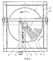
- the apparatus shown in Fig. 1 comprises a support 1 having cooling channels 2, a dispenser 3 and a scraping device 4.
- the support 1 is mounted on a hollow shaft 5, wherein a second hollow shaft 6 extends concentrically.
- the assembly of the shafts 5 and 6 and the support 1 is accommodated in a fixedly arranged encasing 8 so as to be rotatable by means of a driving gear 7.
- the hollow shaft 5 further carries the dispenser 3 mounted so as to be pivotable to and fro through a specific path around the shaft 5 by driving means not further shown.
- the rotatable, hollow shaft 6 is connected with a fixedly disposed coolant supply 9, while the annular space between the jointly rotatable shafts 5 and 6 communicates, via a coupling, with a fixedly disposed coolant drain 10. Coolant fed via the hollow shaft 6 is passed to the cooling channels 2 by means of an annular channel and a feed line 11 or 26 connecting thereto, and returned, via a discharge line 12 or 18, to an annular channel communicating with the annular hollow space between the shafts 5 and 6.
- the dispenser 3 comprises a dispensing member 13 in the form of a sector of a circle.
- the dispensing member 13 comprises a large number of dispensing openings 14, enabling a sector of the support 1 to be supplied, in one operation, with a molten product to be processed, deposited batchwise in a particular pattern.
- the scraping device 4 comprises a blade carrier 15, connected with a carrying tube 17 by ears 16.
- One extremity of the carrying tube 17 is bearing-mounted in a rectangular frame 19 located outside the fixedly disposed encasing 8, which frame 19 is left out in Fig. 1, while the other extremity finds support in a shaft 20, which is in turn supported by the frame 19 again.
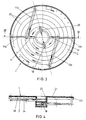
- Figs 3 and 4 show the support 1 with cooling channels 2.
- the support 1 is composed of an annular element 21 provided with a hub part 22 at its central opening and with a collar part 23 at its outer edge.
- a thin plate 24 is attached by means of laser welds 25 in such a pattern that the regions located between the weld seams have a double spiral-shaped configuration, with the ends of the two spirals located opposite each other.
- the regions between the laser welds are inflated under pressure by means of a fluid to form a double spiral-shaped cooling channel 2 due to the bulging of the thin plate 24 between the laser welds 25.
- the feed line 11 divides into a part 11a and a part 11b.
- the part 11a extends to the outer starting region of one spiral-shaped channel 2, while the part 11b further on terminates in the same channel 2, connecting to the discharge line 18 near its inner end.
- the other spiral-shaped channel is fed near its inner end by the feed line 26, while the discharge takes place through the line parts 12a and 12b, meeting in the discharge line 12.
- the coolant flows in opposite directions in the two channels, which, partly in view of the disposition of the supply and the drain and the material thickness of the annular element 21, ensures a maximally even temperature distribution over the support, so that all product deposited on the annular element, dropwise or batchwise, is cooled down to the same extent.
- the support 1 is first brought to the desired temperature by means of the cooling system.
- the dispenser 3 pivotable to and fro, the product to be processed is deposited in liquid form on the top surface of the continuously rotating support 1, where the cooling action of the support provides that the product solidifies, which product is then removed from the support 1 by the scraping device 4 and ends up in a receiving device not further shown.
- annular elements within the casing 8, several annular elements can be disposed, each having its cooling, dispenser and scraper. Further, both the configuration of the cooling channels and the number thereof can be modified as required, while the cooling channels can also be realized in another manner than described.
- the dispenser and the scraper can be constructed in any other suitable manner. In this connection, one may for instance think of casting or metal-removing operations and connecting two or more parts detachably or undetachably. Further, if required, means may be present for creating an inert atmosphere within the casing 8 or exhaust means adapted to exhaust vapors and gases that may have been formed during the processing of the product.
Landscapes
- Chemical & Material Sciences (AREA)
- Engineering & Computer Science (AREA)
- Mechanical Engineering (AREA)
- General Engineering & Computer Science (AREA)
- Organic Chemistry (AREA)
- Chemical Kinetics & Catalysis (AREA)
- Physical Or Chemical Processes And Apparatus (AREA)
- Processing And Handling Of Plastics And Other Materials For Molding In General (AREA)
- Glanulating (AREA)
- Fertilizers (AREA)
- Formation And Processing Of Food Products (AREA)
- Agricultural Chemicals And Associated Chemicals (AREA)
- Vaporization, Distillation, Condensation, Sublimation, And Cold Traps (AREA)
- Feeding, Discharge, Calcimining, Fusing, And Gas-Generation Devices (AREA)
Claims (8)
- Vorrichtung zur Abkühlung und Verarbeitung eines geschmolzenen Produkts in ein granulatförmiges Produkt, umfassend:eine Abstützung, die aus mindestens einem im wesentlichen horizontalen, scheibenförmigen Element besteht, das zur Drehung um eine im wesentlichen vertikale Welle hergerichtet ist,Einrichtungen zum Aufbringen des geschmolzenen Produkts auf jedes scheibenförmige Element der Abstützung,Kühlungseinrichtungen zur Abkühlung der Abstützung, undEinrichtungen zum Entfernen des in Granulatform verfestigten Produkts von der Abstützung, dadurch gekennzeichnet, daß die Kühlungseinrichtungen je scheibenförmigem Element zwei ineinandergreifende, spiralförmige, in sich geschlossene Kühlflüssigkeitskanäle aufweisen, die ein Teil des scheibenförmigem Elements bilden, wobei jeder spiralförmige Kanal ein äußeres und ein inneres Ende hat, und ein spiralförmiger Kanal einen benachbart seinem äußeren Ende gelegenen Kühlflüssigkeitseinlaß und einen benachbart seinem inneren Ende gelegenen Kühlflüssigkeitsauslaß aufweist, wohingegen dies bei dem anderen spiralförmigen Kanal umgekehrt ist, und sich Zufuhr- und Abfuhreinrichtungen für die Kühlflüssigkeit mittig durch das scheibenförmige Element erstrecken, wobei die Kanäle ohne Verbindung mit der Umgebung mit den Zufuhr- und Abfuhreinrichtungen verbunden sind.
- Vorrichtung nach Anspruch 1,
dadurch gekennzeichnet, daß die Einlässe sowie die Auslässe der beiden Kanäle mit einem Ringkanal in der vertikalen Welle verbunden sind. - Vorrichtung nach Anspruch 1 oder 2,
dadurch gekennzeichnet, daß die Abstützung aus einer scheibenförmigen Trägerplattform und einer an deren Unterseite örtlich befestigten, dünnen Platte zusammengesetzt ist, wobei die Platte nach der Befestigung ausgebaucht wird, indem der Zwischenraum zwischen der Trägerplattform und der dünnen Platte in den Bereichen zwischen den örtlichen Befestigungen mittels eines Fluids unter Druck gesetzt wird. - Vorrichtung nach Anspruch 3,
dadurch gekennzeichnet, daß die dünne Platte an der Trägerplattform durch Laserschweißung befestigt ist. - Vorrichtung nach einem der vorstehenden Ansprüche,
dadurch gekennzeichnet, daß die Einrichtungen zum Aufbringen des geschmolzenen Produkts auf die Abstützung einen Verteiler aufweisen, der hergerichtet ist, um das geschmolzene Produkt chargenweise oder tröpfchenweise abzugeben. - Vorrichtung nach Anspruch 5,
dadurch gekennzeichnet, daß die Abstützung ein ringförmiges Element aufweist und der Verteiler hergerichtet ist, um das geschmolzene Produkt in Sektoren abzugeben. - Vorrichtung nach einem der vorstehenden Ansprüche,
dadurch gekennzeichnet, daß die Abstützung aus einer Anzahl von scheibenförmigen Elementen besteht, die vertikal übereinander angeordnet sind, wobei jedes Kühlungskanäle, Verteilereinrichtungen und Einrichtungen zum Entfernen des in Granulatform verfestigten Produkts aufweist. - Vorrichtung nach einem der vorstehenden Ansprüche,
dadurch gekennzeichnet, daß die Abstützung durch ein Gehäuse umgeben ist, das sie von der Umgebung abschließt.
Applications Claiming Priority (3)
| Application Number | Priority Date | Filing Date | Title |
|---|---|---|---|
| NL9400618 | 1994-04-18 | ||
| NL9400618A NL9400618A (nl) | 1994-04-18 | 1994-04-18 | Inrichting voor het koelen en verwerken van een gesmolten produkt tot een granulaatprodukt. |
| PCT/NL1995/000138 WO1995028226A1 (en) | 1994-04-18 | 1995-04-18 | An apparatus for cooling and processing a molten product into a granulate product |
Publications (2)
| Publication Number | Publication Date |
|---|---|
| EP0796141A1 EP0796141A1 (de) | 1997-09-24 |
| EP0796141B1 true EP0796141B1 (de) | 1998-07-01 |
Family
ID=19864083
Family Applications (1)
| Application Number | Title | Priority Date | Filing Date |
|---|---|---|---|
| EP95914579A Expired - Lifetime EP0796141B1 (de) | 1994-04-18 | 1995-04-18 | Einrichtung zur abkühlung und herstellung von granulat aus geschmolzenen produkten |
Country Status (9)
| Country | Link |
|---|---|
| US (1) | US5772187A (de) |
| EP (1) | EP0796141B1 (de) |
| JP (1) | JPH10502294A (de) |
| AT (1) | ATE167815T1 (de) |
| DE (1) | DE69503257T2 (de) |
| DK (1) | DK0796141T3 (de) |
| ES (1) | ES2120195T3 (de) |
| NL (1) | NL9400618A (de) |
| WO (1) | WO1995028226A1 (de) |
Families Citing this family (6)
| Publication number | Priority date | Publication date | Assignee | Title |
|---|---|---|---|---|
| ES2246238T3 (es) | 1999-06-07 | 2006-02-16 | Altana Pharma Ag | Nueva preparacion y forma de administracion que comprende un inhibidor de las bombas de protones labil en medio acido. |
| US6284279B1 (en) | 1999-12-03 | 2001-09-04 | Avecia, Inc. | Phenothiazine in prill form and method for making the same |
| DE10032137B4 (de) * | 2000-07-01 | 2009-04-02 | Allessachemie Gmbh | Verfahren zur Herstellung von Phenothiazin-Granulat mit verbesserten Eigenschaften |
| FR2885544B1 (fr) * | 2005-05-13 | 2009-01-16 | Fai Production Soc Par Actions | Procede et installation de transformation d'un metal a l'etat liquide en un metal a l'etat solide et fragmente |
| JP5193560B2 (ja) * | 2007-10-19 | 2013-05-08 | 三菱マテリアルテクノ株式会社 | テーブル型フレーク製造装置 |
| JP5510349B2 (ja) * | 2011-01-31 | 2014-06-04 | 住友金属鉱山株式会社 | フレーク製造機およびフレーク製造方法 |
Family Cites Families (8)
| Publication number | Priority date | Publication date | Assignee | Title |
|---|---|---|---|---|
| BE547259A (de) * | 1955-04-26 | |||
| US2910744A (en) * | 1955-12-23 | 1959-11-03 | Marvaland Inc | Apparatus for producing metal filaments |
| US3642053A (en) * | 1969-12-09 | 1972-02-15 | Ppg Industries Inc | Method of preparing sodium-lead alloy flakes |
| US4500349A (en) * | 1981-12-24 | 1985-02-19 | The Dow Chemical Company | Production of round salt coated metal granules |
| CH662752A5 (de) * | 1984-05-19 | 1987-10-30 | Glatt Maschinen & Apparatebau | Verfahren zum behandeln eines teilchenfoermigen gutes und einrichtung zur durchfuehrung des verfahrens. |
| JPS6342728A (ja) * | 1986-08-07 | 1988-02-23 | Hosokawa Micron Kk | 粉粒体処理方法及び粉粒体処理装置 |
| CH671351A5 (de) * | 1987-04-10 | 1989-08-31 | Battelle Memorial Institute | |
| JPH0622667B2 (ja) * | 1989-07-04 | 1994-03-30 | 不二パウダル株式会社 | 混合・造粒機能を備えた粉粒体処理機 |
-
1994
- 1994-04-18 NL NL9400618A patent/NL9400618A/nl not_active Application Discontinuation
-
1995
- 1995-04-18 EP EP95914579A patent/EP0796141B1/de not_active Expired - Lifetime
- 1995-04-18 ES ES95914579T patent/ES2120195T3/es not_active Expired - Lifetime
- 1995-04-18 JP JP7526878A patent/JPH10502294A/ja active Pending
- 1995-04-18 AT AT95914579T patent/ATE167815T1/de not_active IP Right Cessation
- 1995-04-18 WO PCT/NL1995/000138 patent/WO1995028226A1/en not_active Ceased
- 1995-04-18 DE DE69503257T patent/DE69503257T2/de not_active Expired - Fee Related
- 1995-04-18 US US08/727,410 patent/US5772187A/en not_active Expired - Lifetime
- 1995-04-18 DK DK95914579T patent/DK0796141T3/da active
Also Published As
| Publication number | Publication date |
|---|---|
| ES2120195T3 (es) | 1998-10-16 |
| NL9400618A (nl) | 1995-12-01 |
| EP0796141A1 (de) | 1997-09-24 |
| WO1995028226A1 (en) | 1995-10-26 |
| DK0796141T3 (da) | 1998-11-16 |
| ATE167815T1 (de) | 1998-07-15 |
| DE69503257D1 (de) | 1998-08-06 |
| JPH10502294A (ja) | 1998-03-03 |
| US5772187A (en) | 1998-06-30 |
| DE69503257T2 (de) | 1998-11-05 |
Similar Documents
| Publication | Publication Date | Title |
|---|---|---|
| EP0796141B1 (de) | Einrichtung zur abkühlung und herstellung von granulat aus geschmolzenen produkten | |
| JP4200189B2 (ja) | パネル式スプレー冷却炉ルーフ | |
| EP1243316A3 (de) | Prillduse für Granuliervorrichtung | |
| CN109290535B (zh) | 非晶带材连续生产设备 | |
| US4245972A (en) | Granulating apparatus | |
| EP0078272A1 (de) | Vorrichtung zum versprühen von metall oder anderem material | |
| US6203761B1 (en) | Fluidized bed apparatus having spray chamber with pivotal slats | |
| US4217082A (en) | Spin cup means for the production of metal powder | |
| CN103764320B (zh) | 炉渣粒化设备 | |
| CA1120677A (en) | Apparatus for granulating melts of plastics material | |
| KR101018897B1 (ko) | 금속 용융물을 연속으로 캐스팅하기 위한 장치 | |
| JP2523806B2 (ja) | 連続鋳造機、及びその方法 | |
| JPH0376718A (ja) | ポリマーの成形装置 | |
| JPH0317206A (ja) | 急冷凝固金属粉末製造装置 | |
| CN103781575B (zh) | 渣粒化设备 | |
| EP0592539A1 (de) | Verfahren und vorrichtung zum kontinuierlichen giessen von metallbändern | |
| JPH0114964B2 (de) | ||
| GB2500039A (en) | Rotary slag granulator with an annular metal disc and central cylinder containing plug of refractory material | |
| US4231227A (en) | Prill tower rake | |
| KR100590810B1 (ko) | 고속 주조용 다중분무성형장치 | |
| GB2500038A (en) | Rotary slag atomising granulator with metal disk and cooling system | |
| JPH0623743A (ja) | 低粘度樹脂の造粒装置 | |
| JPH0674446B2 (ja) | 急冷凝固金属粉末製造装置 | |
| SU1710113A1 (ru) | Устройство дл гранулировани расплавов | |
| SU1611434A1 (ru) | Устройство дл гранулировани |
Legal Events
| Date | Code | Title | Description |
|---|---|---|---|
| PUAI | Public reference made under article 153(3) epc to a published international application that has entered the european phase |
Free format text: ORIGINAL CODE: 0009012 |
|
| 17P | Request for examination filed |
Effective date: 19961011 |
|
| AK | Designated contracting states |
Kind code of ref document: A1 Designated state(s): AT BE CH DE DK ES FR GB GR IE IT LI LU NL PT SE |
|
| GRAG | Despatch of communication of intention to grant |
Free format text: ORIGINAL CODE: EPIDOS AGRA |
|
| 17Q | First examination report despatched |
Effective date: 19971028 |
|
| GRAG | Despatch of communication of intention to grant |
Free format text: ORIGINAL CODE: EPIDOS AGRA |
|
| GRAH | Despatch of communication of intention to grant a patent |
Free format text: ORIGINAL CODE: EPIDOS IGRA |
|
| GRAH | Despatch of communication of intention to grant a patent |
Free format text: ORIGINAL CODE: EPIDOS IGRA |
|
| GRAA | (expected) grant |
Free format text: ORIGINAL CODE: 0009210 |
|
| AK | Designated contracting states |
Kind code of ref document: B1 Designated state(s): AT BE CH DE DK ES FR GB GR IE IT LI LU NL PT SE |
|
| REF | Corresponds to: |
Ref document number: 167815 Country of ref document: AT Date of ref document: 19980715 Kind code of ref document: T |
|
| REG | Reference to a national code |
Ref country code: CH Ref legal event code: EP |
|
| REG | Reference to a national code |
Ref country code: CH Ref legal event code: NV Representative=s name: R. A. EGLI & CO. PATENTANWAELTE |
|
| REF | Corresponds to: |
Ref document number: 69503257 Country of ref document: DE Date of ref document: 19980806 |
|
| ET | Fr: translation filed | ||
| REG | Reference to a national code |
Ref country code: IE Ref legal event code: FG4D |
|
| REG | Reference to a national code |
Ref country code: ES Ref legal event code: FG2A Ref document number: 2120195 Country of ref document: ES Kind code of ref document: T3 |
|
| REG | Reference to a national code |
Ref country code: DK Ref legal event code: T3 |
|
| REG | Reference to a national code |
Ref country code: PT Ref legal event code: SC4A Free format text: AVAILABILITY OF NATIONAL TRANSLATION Effective date: 19980813 |
|
| PLBE | No opposition filed within time limit |
Free format text: ORIGINAL CODE: 0009261 |
|
| STAA | Information on the status of an ep patent application or granted ep patent |
Free format text: STATUS: NO OPPOSITION FILED WITHIN TIME LIMIT |
|
| 26N | No opposition filed | ||
| REG | Reference to a national code |
Ref country code: GB Ref legal event code: IF02 |
|
| PGFP | Annual fee paid to national office [announced via postgrant information from national office to epo] |
Ref country code: PT Payment date: 20090320 Year of fee payment: 15 |
|
| PGFP | Annual fee paid to national office [announced via postgrant information from national office to epo] |
Ref country code: IE Payment date: 20090414 Year of fee payment: 15 Ref country code: ES Payment date: 20090430 Year of fee payment: 15 Ref country code: DK Payment date: 20090415 Year of fee payment: 15 |
|
| PGFP | Annual fee paid to national office [announced via postgrant information from national office to epo] |
Ref country code: SE Payment date: 20090427 Year of fee payment: 15 Ref country code: NL Payment date: 20090427 Year of fee payment: 15 Ref country code: LU Payment date: 20090414 Year of fee payment: 15 Ref country code: IT Payment date: 20090430 Year of fee payment: 15 Ref country code: FR Payment date: 20090403 Year of fee payment: 15 Ref country code: DE Payment date: 20090422 Year of fee payment: 15 Ref country code: AT Payment date: 20090429 Year of fee payment: 15 |
|
| PGFP | Annual fee paid to national office [announced via postgrant information from national office to epo] |
Ref country code: BE Payment date: 20090519 Year of fee payment: 15 |
|
| PGFP | Annual fee paid to national office [announced via postgrant information from national office to epo] |
Ref country code: GR Payment date: 20090402 Year of fee payment: 15 Ref country code: GB Payment date: 20090409 Year of fee payment: 15 Ref country code: CH Payment date: 20090723 Year of fee payment: 15 |
|
| BERE | Be: lapsed |
Owner name: *GOUDSCHE MACHINEFABRIEK B.V. Effective date: 20100430 |
|
| REG | Reference to a national code |
Ref country code: NL Ref legal event code: V1 Effective date: 20101101 |
|
| EUG | Se: european patent has lapsed | ||
| REG | Reference to a national code |
Ref country code: CH Ref legal event code: PL |
|
| REG | Reference to a national code |
Ref country code: DK Ref legal event code: EBP |
|
| GBPC | Gb: european patent ceased through non-payment of renewal fee |
Effective date: 20100418 |
|
| REG | Reference to a national code |
Ref country code: IE Ref legal event code: MM4A |
|
| REG | Reference to a national code |
Ref country code: FR Ref legal event code: ST Effective date: 20101230 |
|
| PG25 | Lapsed in a contracting state [announced via postgrant information from national office to epo] |
Ref country code: NL Free format text: LAPSE BECAUSE OF NON-PAYMENT OF DUE FEES Effective date: 20101101 Ref country code: IE Free format text: LAPSE BECAUSE OF NON-PAYMENT OF DUE FEES Effective date: 20100419 Ref country code: FR Free format text: LAPSE BECAUSE OF NON-PAYMENT OF DUE FEES Effective date: 20100430 Ref country code: AT Free format text: LAPSE BECAUSE OF NON-PAYMENT OF DUE FEES Effective date: 20100418 |
|
| PG25 | Lapsed in a contracting state [announced via postgrant information from national office to epo] |
Ref country code: PT Free format text: LAPSE BECAUSE OF NON-PAYMENT OF DUE FEES Effective date: 20101018 Ref country code: LI Free format text: LAPSE BECAUSE OF NON-PAYMENT OF DUE FEES Effective date: 20100430 Ref country code: DE Free format text: LAPSE BECAUSE OF NON-PAYMENT OF DUE FEES Effective date: 20101103 Ref country code: CH Free format text: LAPSE BECAUSE OF NON-PAYMENT OF DUE FEES Effective date: 20100430 |
|
| PG25 | Lapsed in a contracting state [announced via postgrant information from national office to epo] |
Ref country code: BE Free format text: LAPSE BECAUSE OF NON-PAYMENT OF DUE FEES Effective date: 20100430 Ref country code: GR Free format text: LAPSE BECAUSE OF NON-PAYMENT OF DUE FEES Effective date: 20101103 Ref country code: IT Free format text: LAPSE BECAUSE OF NON-PAYMENT OF DUE FEES Effective date: 20100418 Ref country code: GB Free format text: LAPSE BECAUSE OF NON-PAYMENT OF DUE FEES Effective date: 20100418 |
|
| PG25 | Lapsed in a contracting state [announced via postgrant information from national office to epo] |
Ref country code: DK Free format text: LAPSE BECAUSE OF NON-PAYMENT OF DUE FEES Effective date: 20100503 |
|
| REG | Reference to a national code |
Ref country code: ES Ref legal event code: FD2A Effective date: 20110718 |
|
| PG25 | Lapsed in a contracting state [announced via postgrant information from national office to epo] |
Ref country code: ES Free format text: LAPSE BECAUSE OF NON-PAYMENT OF DUE FEES Effective date: 20110706 |
|
| PG25 | Lapsed in a contracting state [announced via postgrant information from national office to epo] |
Ref country code: ES Free format text: LAPSE BECAUSE OF NON-PAYMENT OF DUE FEES Effective date: 20100419 |
|
| PG25 | Lapsed in a contracting state [announced via postgrant information from national office to epo] |
Ref country code: LU Free format text: LAPSE BECAUSE OF NON-PAYMENT OF DUE FEES Effective date: 20100418 Ref country code: SE Free format text: LAPSE BECAUSE OF NON-PAYMENT OF DUE FEES Effective date: 20100419 |