EP0795708B1 - Klemmschelle - Google Patents
Klemmschelle Download PDFInfo
- Publication number
- EP0795708B1 EP0795708B1 EP19960112410 EP96112410A EP0795708B1 EP 0795708 B1 EP0795708 B1 EP 0795708B1 EP 19960112410 EP19960112410 EP 19960112410 EP 96112410 A EP96112410 A EP 96112410A EP 0795708 B1 EP0795708 B1 EP 0795708B1
- Authority
- EP
- European Patent Office
- Prior art keywords
- webs
- grooves
- portions
- cross
- thickened
- Prior art date
- Legal status (The legal status is an assumption and is not a legal conclusion. Google has not performed a legal analysis and makes no representation as to the accuracy of the status listed.)
- Expired - Lifetime
Links
- 230000007423 decrease Effects 0.000 claims description 5
- 235000001674 Agaricus brunnescens Nutrition 0.000 claims description 2
- 238000010276 construction Methods 0.000 claims 1
- 238000000926 separation method Methods 0.000 claims 1
- 230000008719 thickening Effects 0.000 description 51
- 230000015572 biosynthetic process Effects 0.000 description 4
- 238000009434 installation Methods 0.000 description 3
- 238000006073 displacement reaction Methods 0.000 description 2
- 238000005259 measurement Methods 0.000 description 2
- 238000000034 method Methods 0.000 description 2
- 230000008878 coupling Effects 0.000 description 1
- 238000010168 coupling process Methods 0.000 description 1
- 238000005859 coupling reaction Methods 0.000 description 1
Images


Classifications
-
- F—MECHANICAL ENGINEERING; LIGHTING; HEATING; WEAPONS; BLASTING
- F16—ENGINEERING ELEMENTS AND UNITS; GENERAL MEASURES FOR PRODUCING AND MAINTAINING EFFECTIVE FUNCTIONING OF MACHINES OR INSTALLATIONS; THERMAL INSULATION IN GENERAL
- F16L—PIPES; JOINTS OR FITTINGS FOR PIPES; SUPPORTS FOR PIPES, CABLES OR PROTECTIVE TUBING; MEANS FOR THERMAL INSULATION IN GENERAL
- F16L3/00—Supports for pipes, cables or protective tubing, e.g. hangers, holders, clamps, cleats, clips, brackets
- F16L3/22—Supports for pipes, cables or protective tubing, e.g. hangers, holders, clamps, cleats, clips, brackets specially adapted for supporting a number of parallel pipes at intervals
- F16L3/222—Supports for pipes, cables or protective tubing, e.g. hangers, holders, clamps, cleats, clips, brackets specially adapted for supporting a number of parallel pipes at intervals having single supports directly connected together
-
- F—MECHANICAL ENGINEERING; LIGHTING; HEATING; WEAPONS; BLASTING
- F16—ENGINEERING ELEMENTS AND UNITS; GENERAL MEASURES FOR PRODUCING AND MAINTAINING EFFECTIVE FUNCTIONING OF MACHINES OR INSTALLATIONS; THERMAL INSULATION IN GENERAL
- F16L—PIPES; JOINTS OR FITTINGS FOR PIPES; SUPPORTS FOR PIPES, CABLES OR PROTECTIVE TUBING; MEANS FOR THERMAL INSULATION IN GENERAL
- F16L3/00—Supports for pipes, cables or protective tubing, e.g. hangers, holders, clamps, cleats, clips, brackets
- F16L3/08—Supports for pipes, cables or protective tubing, e.g. hangers, holders, clamps, cleats, clips, brackets substantially surrounding the pipe, cable or protective tubing
- F16L3/12—Supports for pipes, cables or protective tubing, e.g. hangers, holders, clamps, cleats, clips, brackets substantially surrounding the pipe, cable or protective tubing comprising a member substantially surrounding the pipe, cable or protective tubing
- F16L3/13—Supports for pipes, cables or protective tubing, e.g. hangers, holders, clamps, cleats, clips, brackets substantially surrounding the pipe, cable or protective tubing comprising a member substantially surrounding the pipe, cable or protective tubing and engaging it by snap action
Definitions
- the invention relates to a clamp see e.g. US-A-4 306 697 and EP-A-555550 in particular made of plastic, with a base part for stationary Arrangement of the clamp and a fork-like Clamping part with clamping arms or similar clamping elements for clamping a pipe or the like cylindrical long molded part, with the base part parallel to the pipe duct of the clamping part aligned side surfaces of clamps with similarly designed baying devices are formed, with baying means from parallel for pipe passage of the clamping part, from one side surface of the base part projecting webs with thickened ends and out in the other side surface of the base part formed with grooves accordingly of the thickening of the web there is an enlarged groove base.
- the base part is approximately cuboid.
- the longer side faces the base part are transverse to the direction of a clamped pipe or the like directed while the narrow base sides are parallel to it.
- the narrow base sides have the baying means, with a groove on one narrow side and on the other a projection is formed on the other narrow side.
- the groove is at its ends, which is made of the wide plinth surfaces emerge openly.
- the footbridge runs across the entire Width of the narrow base part.
- the groove is in the Groove provided with an extension during the Web has a thickening at its free end.
- the training allows several similar clamps to be arranged side by side and to each other connect by a parallel displacement of the neighboring clamps in such a way that the groove of a clamp to be attached to a web an already installed clamp parallel to the direction a clamped tube is pushed on.
- the long side surfaces of the Base part groove and web-like guide elements be designed to be pushed (transverse sliding) on an installation rail or the like enable.
- Parallel shift to each other for the purpose to connect the baying. But sometimes it's because a small installation space required, such Clamp across an existing clamp to arrange and introduce, then the coupling by moving the parts parallel to each other is possible.
- the invention proposes that on the side surface of the Base part several webs at a distance from each other, are parallel to each other, wherein the cross section of the web is different and the cross section the thickening analogous to the web cross-sections is formed differently, and that with the Grooved side surface of the base part correspondingly shaped grooves are, in the baying position of adjacent clamps all thickening of the webs in all Interact appropriately with extensions of the groove bases, but at least those for separating the clamps in line areas of thickened areas subject to tension and extensions are close to each other.
- the thickening and the corresponding grooves will be the manual connection of the Clamps relieved each other when this Clamps are fed across each other so that the side surfaces of the Pedestals are fed orthogonally to each other, for example when such clamps in Installation rails are guided, which cross to Direction of the pipes to be clamped arranged are.
- the lining up of the clamps is both through Threading and moving the adjacent clamps in the direction parallel to the course of a jammed Pipe or the like cylindrical long molded part as also by shifting two parallel to each other aligned clamps to each other.
- the thickenings taper towards the free end are shaped.
- a particularly preferred and suitable further education is seen in the fact that on both sides of the Base with webs with thickening and grooves Extensions alternately one above the other are trained.
- the arrangement and formation of the grooves with extensions and webs is made with thickenings so that their Cross-sectional dimension from the base surface of the base part towards the base surface carrying the clamping part decreases.
- the web is included Thickening that is in close proximity to the base of the Base part is arranged, the one with the largest Cross-sectional dimension and also the associated groove, while increasing distance from the base surface of the base part in the direction of the clamping arms of the Base part webs with a smaller cross-section, Thickenings with a smaller cross-section and accordingly also grooves and extensions with a smaller cross-section are trained.
- a possibly preferred training is in it seen that the webs with thickening and the grooves with extensions in cross section mushroom-like are trained.
- the thickenings the webs and the extensions of the grooves in cross section are shaped like a circular arc.
- the webs with thickenings are arranged so that between adjacent webs with thickened areas facing each other Grooves and thickening flanks corresponding grooves are shaped with extensions.
- each other neighboring webs with thickening and grooves Extensions are designed so that when lateral guidance Another clamp first in cross section largest thickened in the largest dimensioned grooves with extensions partially depressible are before the next smallest thickening in cross section engages in the associated groove.
- the larger ones in cross section Thickenings continue over the side alignment of the base part protrude than the smaller in cross section Thickening, so that when merging neighboring Clamps are initially larger in cross section dimensioned thickenings in the corresponding grooves partially intervene before the next larger thickening of a neighboring bridge into the correspondingly dimensioned one engages another groove and as a result then that or further thickenings with smaller cross-sections at the web ends in the corresponding grooves below intervention.
- a certain power distribution reached what for the assembly process is advantageous.
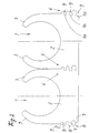
- clamps 1 are made of plastic shown, which is a base part 2 for fixed arrangement the clamp 1 and a fork-like clamping part with clamp arms 3 for clamping a pipe or the like.
- the base part 2 is in the essentially cuboid, the longer one Side face of the cuboid in the drawing in front and behind lies while the narrow side faces of the cuboid are directed orthogonally.
- the long Grooves 4 are formed on the side faces of the base part 2.
- the clamp 1 is with these grooves 4 on rails, for example plastic rails, can be slid across, which are profiled in a C-shape and those with their angled ends pointing towards each other engage corresponding grooves 4 of a clamp 1.
- the base part 4 On the base part 4 are parallel to the pipe bushing (parallel to the perpendicular to the drawing level according to Figure 1 for example) directed side surfaces Baying means 5, 6 for baying clamps 1 arranged with similarly designed baying means.
- the baying means 5, 6 consist of parallel to Pipe bushing of the clamping part, from a Side surface of the base part 2 protruding webs 7 with thickened ends 8 and on the other side surface of the base part formed grooves 9 with accordingly the web thickening extended groove base 10.
- Im Embodiment are on both side surfaces of the Base part 2 in sequence of grooves 9 and webs 7 with Thickenings 8 or extensions 10 are provided.
- the Bridge cross section different and the cross section the thickening 8 at the web ends analogous to the web cross sections is designed differently.
- the groove width corresponding to the Web measurement decreases and its extension 10 also decreases according to the thickening dimension.
- the stringing of such clamps 1 can both by Threading and moving the adjacent clamps 1 in the direction parallel to the course of a jammed Tube or the like take place as well as by transverse displacement of two aligned parallel to each other Clamps towards each other.
- the Mouths of the grooves 9 are shaped as well how the thickenings 8 towards their free end are tapered to provide an introducer when connecting the baying devices.
- both are Side surfaces of the base 2 each with webs 7 Thickenings 8 and grooves 9 with extensions 10 alternately trained one above the other.
- the arrangement and Formation of the grooves 9 with extensions 10 and webs 7 with thickenings 8 is made so that their cross-sectional dimension from the base surface (in the drawing figure 1 and 2 below) of the base part 2 to which the Clamping part bearing base surface decreases.
- the webs 7 with thickenings 8 and the grooves 9 with Extensions 10 are in the embodiment according to Figure 1 formed like a mushroom head.
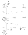
- the Embodiment according to Figures 2 to 8 are Thickenings 8 of the webs 7 and the extensions 10 of the grooves 9 shaped like a circular arc in cross section.
- the Web 7 with thickenings 8 are arranged so that between adjacent webs 7 with 8 thickening the mutually facing web flanks and Corresponding grooves 9 with corresponding thickening flanks Extensions 10 are shaped.
Landscapes
- Engineering & Computer Science (AREA)
- General Engineering & Computer Science (AREA)
- Mechanical Engineering (AREA)
- Clamps And Clips (AREA)
- Supports For Pipes And Cables (AREA)
- Hand Tools For Fitting Together And Separating, Or Other Hand Tools (AREA)
Description
Es zeigt:
- Fig. 1
- eine erste Ausführungsform von Klemmschellen in Ansicht;
- Fig. 2
- eine Variante in gleicher Ansicht;
- Fig. 3 bis 8
- Detaildarstellungen der Variante gemäß Figur 2 in unterschiedlicher Montageposition.
Claims (9)
- Klemmschelle, insbesondere aus Kunststoff, mit einem Sockelteil zur ortsfesten Anordnung der Klemmschelle und einem gabelähnlichen Klemmteil mit Klemmarmen oder dergleichen Klemmelementen zum Einklemmen eines Rohres oder eines ähnlichen zylindrischen Langformteiles, wobei am Sockelteil an den parallel zur Rohrdurchführung des Klemmteils gerichteten Seitenflächen Anreihmittel zum Anreihen von Klemmschellen mit gleichartig ausgebildeten Anreihmitteln ausgebildet sind, wobei die Anreihmittel aus parallel zur Rohrdurchführung des Klemmteils verlaufenden, von einer Seitenfläche des Sockelteils abragenden Stegen mit verdickten Enden und aus in der anderen Seitenfläche des Sockelteils ausgebildeten Nuten mit entsprechend der Stegverdickung erweitertem Nutgrund bestehen, dadurch gekennzeichnet, daß an der mit Stegen (7) versehenen Seitenfläche des Sockelteils (2) mehrere Stege (7) mit Abstand übereinander, parallel zueinander verlaufend ausgebildet sind, wobei der Stegquerschnitt unterschiedlich und der Querschnitt der Verdickungen (8) analog den Stegquerschnitten unterschiedlich ausgebildet ist, und daß an der mit Nuten (9) versehenen Seitenfläche des Sockelteils (2) entsprechend unterschiedlich geformte Nuten (9) ausgebildet sind, wobei in der Anreihposition benachbarter Klemmschellen (1) sämtliche Verdickungen (8) der Stege (7) in sämtlichen Erweiterungen (10) der Nutgründe passend eingreifen, mindestens aber die zum Trennen der angereihten Klemmschellen (1) auf Zug belasteten Flächen (11) von Verdickungen (8) und Erweiterungen (10) aneinander anliegen.
- Klemmschelle nach Anspruch 1, dadurch gekennzeichnet, daß die Nutmündungen sich erweiternd geformt sind.
- Klemmschelle nach Anspruch 1 oder 2, dadurch gekennzeichnet, daß die Verdickungen (8) sich zum freien Ende hin verjüngend geformt sind.
- Klemmschelle nach einem der Ansprüche 1 bis 3, dadurch gekennzeichnet, daß an beiden Seitenflächen des Sockels (2) jeweils Stege (7) mit Verdickungen (8) und Nuten (9) mit Erweiterungen (10) jeweils abwechselnd übereinander ausgebildet sind.
- Klemmschelle nach einem der Ansprüche 1 bis 4, dadurch gekennzeichnet, daß die Anordnung und Ausbildung der Nuten (9) mit Erweiterungen (10) und Stege (7) mit Verdickungen (8) so vorgenommen ist, daß deren Querschnittsabmessung von der Basisfläche des Sockelteils (2) zu der das Klemmteil tragenden Sockelfläche hin abnimmt.
- Klemmschelle nach einem der Ansprüche 1 bis 5, dadurch gekennzeichnet, daß die Stege (7) mit Verdickungen (8) und die Nuten (9) mit Erweiterungen (10) im Querschnitt pilzkopfartig ausgebildet sind.
- Klemmschelle nach einem der Ansprüche 1 bis 5, dadurch gekennzeichnet, daß die Verdickungen (8) der Stege (7) und die Erweiterungen (10) der Nuten (9) im Querschnitt kreisbogenartig geformt sind.
- Klemmschelle nach einem der Ansprüche 1 bis 7, dadurch gekennzeichnet, daß die Stege (7) mit Verdickungen (8) so angeordnet sind, daß zwischen benachbarten Stegen (7) mit Verdickungen (8) durch die einander zugewandten Stegflanken und Verdickungsflanken entsprechende Nuten (9) mit Erweiterungen (10) geformt sind.
- Klemmschelle nach einem der Ansprüche 1 bis 8, dadurch gekennzeichnet, daß die einander benachbarten Stege (7) mit Verdickungen (8) und Nuten (9) mit Erweiterungen (10) so ausgebildet sind, daß beim Querzuführen einer weiteren Klemmschelle (1) zunächst die im Querschnitt am größten bemessenen Nuten (9) mit Erweiterungen (10) teilweise eindrückbar sind, bevor die in Querschnitt nächst kleinere Verdickung (8) in die zugehörige Nut (9) eingreift.
Applications Claiming Priority (2)
| Application Number | Priority Date | Filing Date | Title |
|---|---|---|---|
| DE19609440A DE19609440C1 (de) | 1995-11-01 | 1996-03-11 | Klemmschelle |
| DE19609440 | 1996-03-11 |
Publications (3)
| Publication Number | Publication Date |
|---|---|
| EP0795708A2 EP0795708A2 (de) | 1997-09-17 |
| EP0795708A3 EP0795708A3 (de) | 1999-06-09 |
| EP0795708B1 true EP0795708B1 (de) | 2001-04-18 |
Family
ID=7787902
Family Applications (1)
| Application Number | Title | Priority Date | Filing Date |
|---|---|---|---|
| EP19960112410 Expired - Lifetime EP0795708B1 (de) | 1996-03-11 | 1996-08-01 | Klemmschelle |
Country Status (3)
| Country | Link |
|---|---|
| EP (1) | EP0795708B1 (de) |
| ES (1) | ES2157375T3 (de) |
| PT (1) | PT795708E (de) |
Families Citing this family (2)
| Publication number | Priority date | Publication date | Assignee | Title |
|---|---|---|---|---|
| EP1746321A1 (de) | 2005-07-22 | 2007-01-24 | IMET S.r.l. | Befestigungseinrichtung für zylindrische Elemente, insbesondere Rohrleitungen und Kabel |
| NL2022976B1 (en) * | 2019-04-18 | 2020-10-26 | Hemmink B V | Saddle clamp |
Family Cites Families (3)
| Publication number | Priority date | Publication date | Assignee | Title |
|---|---|---|---|---|
| US4306697A (en) * | 1980-06-16 | 1981-12-22 | Mathews Lyle H | Conduit spacer system |
| DE9201892U1 (de) * | 1992-02-14 | 1992-04-02 | Hermann Kleinhuis GmbH & Co KG, 5880 Lüdenscheid | Rohrschnappschelle für Elektroinstallationsrohre |
| DE9314862U1 (de) * | 1993-09-30 | 1994-01-20 | Reiku GmbH, 51674 Wiehl | Haltersystem für Rohre o.dgl. |
-
1996
- 1996-08-01 EP EP19960112410 patent/EP0795708B1/de not_active Expired - Lifetime
- 1996-08-01 PT PT96112410T patent/PT795708E/pt unknown
- 1996-08-01 ES ES96112410T patent/ES2157375T3/es not_active Expired - Lifetime
Also Published As
| Publication number | Publication date |
|---|---|
| EP0795708A2 (de) | 1997-09-17 |
| EP0795708A3 (de) | 1999-06-09 |
| ES2157375T3 (es) | 2001-08-16 |
| PT795708E (pt) | 2001-07-31 |
Similar Documents
| Publication | Publication Date | Title |
|---|---|---|
| DE2647235C2 (de) | Distanzhalter für durch Schutzrohre hindurchgeführte Rohre | |
| DE2431679A1 (de) | Rohrleitungsverbinder in elementbauweise | |
| WO2010145744A1 (de) | Profilstabverbindungssystem | |
| DE3516448C1 (de) | Energieführungskette | |
| DE4121433C1 (de) | ||
| DE19820651B4 (de) | Leitungsführungsanordnung mit einer zugentlastenden Befestigung wenigstens einer in der Leitungsführungsanordnung geführten Leitung | |
| DE3838957C2 (de) | ||
| EP0308958A2 (de) | Energieführungskette | |
| WO2019007546A1 (de) | Kabelführungsmittel zur anordnung an einem profilstab | |
| DE2504476B2 (de) | Verbindungsglied zum Verbinden von zwei senkrecht zueinander verlaufenden Profilstaben | |
| DE19609440C1 (de) | Klemmschelle | |
| EP0795708B1 (de) | Klemmschelle | |
| DE102019101180A1 (de) | Halter | |
| EP1229282B1 (de) | Adapter zur Klemmschellemontage | |
| DE4312340C2 (de) | Dübel | |
| EP1516129B1 (de) | Linearwälzlager | |
| DE19719013C2 (de) | Mit einem Wandhalter versehenes, im Querschnitt U-förmiges Halteprofil für eine Trennwand | |
| DE2907850C2 (de) | Rohrschelle | |
| DE19615144C2 (de) | Verbindung eines Sockels eines Kabelverteilerschrankes mit dessen Aufbau | |
| EP0693638A1 (de) | Schleppkette zur Aufnahme mindestens eines Leitungsgliedes sowie Arbeitsverfahren zum Einlegen desselben in die Schleppkette | |
| DE19817427A1 (de) | Klemmverbinder | |
| DE9415686U1 (de) | Lösbare Schnappverbindung | |
| DE3734875C2 (de) | ||
| DE3338841A1 (de) | Fahrschiene fuer einschienenhaengebahn | |
| DE4303935A1 (de) | Kreuzverbinder |
Legal Events
| Date | Code | Title | Description |
|---|---|---|---|
| PUAI | Public reference made under article 153(3) epc to a published international application that has entered the european phase |
Free format text: ORIGINAL CODE: 0009012 |
|
| AK | Designated contracting states |
Kind code of ref document: A2 Designated state(s): BE ES IT LU NL PT |
|
| PUAL | Search report despatched |
Free format text: ORIGINAL CODE: 0009013 |
|
| AK | Designated contracting states |
Kind code of ref document: A3 Designated state(s): BE ES IT LU NL PT |
|
| 17P | Request for examination filed |
Effective date: 19990617 |
|
| RAP1 | Party data changed (applicant data changed or rights of an application transferred) |
Owner name: OBO BETTERMANN GMBH & CO. KG. |
|
| GRAG | Despatch of communication of intention to grant |
Free format text: ORIGINAL CODE: EPIDOS AGRA |
|
| GRAG | Despatch of communication of intention to grant |
Free format text: ORIGINAL CODE: EPIDOS AGRA |
|
| GRAH | Despatch of communication of intention to grant a patent |
Free format text: ORIGINAL CODE: EPIDOS IGRA |
|
| 17Q | First examination report despatched |
Effective date: 20001012 |
|
| GRAH | Despatch of communication of intention to grant a patent |
Free format text: ORIGINAL CODE: EPIDOS IGRA |
|
| GRAA | (expected) grant |
Free format text: ORIGINAL CODE: 0009210 |
|
| AK | Designated contracting states |
Kind code of ref document: B1 Designated state(s): BE ES IT LU NL PT |
|
| ITF | It: translation for a ep patent filed | ||
| REG | Reference to a national code |
Ref country code: PT Ref legal event code: SC4A Free format text: AVAILABILITY OF NATIONAL TRANSLATION Effective date: 20010424 |
|
| PG25 | Lapsed in a contracting state [announced via postgrant information from national office to epo] |
Ref country code: LU Free format text: LAPSE BECAUSE OF EXPIRATION OF PROTECTION Effective date: 20010801 |
|
| REG | Reference to a national code |
Ref country code: ES Ref legal event code: FG2A Ref document number: 2157375 Country of ref document: ES Kind code of ref document: T3 |
|
| PLBE | No opposition filed within time limit |
Free format text: ORIGINAL CODE: 0009261 |
|
| STAA | Information on the status of an ep patent application or granted ep patent |
Free format text: STATUS: NO OPPOSITION FILED WITHIN TIME LIMIT |
|
| 26N | No opposition filed | ||
| PGFP | Annual fee paid to national office [announced via postgrant information from national office to epo] |
Ref country code: NL Payment date: 20140820 Year of fee payment: 19 |
|
| PGFP | Annual fee paid to national office [announced via postgrant information from national office to epo] |
Ref country code: ES Payment date: 20140826 Year of fee payment: 19 |
|
| PGFP | Annual fee paid to national office [announced via postgrant information from national office to epo] |
Ref country code: PT Payment date: 20140203 Year of fee payment: 19 Ref country code: IT Payment date: 20140828 Year of fee payment: 19 |
|
| PGFP | Annual fee paid to national office [announced via postgrant information from national office to epo] |
Ref country code: BE Payment date: 20140820 Year of fee payment: 19 |
|
| REG | Reference to a national code |
Ref country code: PT Ref legal event code: MM4A Free format text: LAPSE DUE TO NON-PAYMENT OF FEES Effective date: 20160201 |
|
| PG25 | Lapsed in a contracting state [announced via postgrant information from national office to epo] |
Ref country code: IT Free format text: LAPSE BECAUSE OF NON-PAYMENT OF DUE FEES Effective date: 20150801 |
|
| REG | Reference to a national code |
Ref country code: NL Ref legal event code: MM Effective date: 20150901 |
|
| PG25 | Lapsed in a contracting state [announced via postgrant information from national office to epo] |
Ref country code: PT Free format text: LAPSE BECAUSE OF NON-PAYMENT OF DUE FEES Effective date: 20160201 |
|
| PG25 | Lapsed in a contracting state [announced via postgrant information from national office to epo] |
Ref country code: NL Free format text: LAPSE BECAUSE OF NON-PAYMENT OF DUE FEES Effective date: 20150901 |
|
| REG | Reference to a national code |
Ref country code: ES Ref legal event code: FD2A Effective date: 20160927 |
|
| PG25 | Lapsed in a contracting state [announced via postgrant information from national office to epo] |
Ref country code: ES Free format text: LAPSE BECAUSE OF NON-PAYMENT OF DUE FEES Effective date: 20150802 Ref country code: PT Free format text: LAPSE BECAUSE OF EXPIRATION OF PROTECTION Effective date: 20160809 |
|
| PG25 | Lapsed in a contracting state [announced via postgrant information from national office to epo] |
Ref country code: BE Free format text: LAPSE BECAUSE OF NON-PAYMENT OF DUE FEES Effective date: 20150831 Ref country code: PT Free format text: LAPSE BECAUSE OF EXPIRATION OF PROTECTION Effective date: 20160208 |