EP0795708B1 - Pipe clamp - Google Patents
Pipe clamp Download PDFInfo
- Publication number
- EP0795708B1 EP0795708B1 EP19960112410 EP96112410A EP0795708B1 EP 0795708 B1 EP0795708 B1 EP 0795708B1 EP 19960112410 EP19960112410 EP 19960112410 EP 96112410 A EP96112410 A EP 96112410A EP 0795708 B1 EP0795708 B1 EP 0795708B1
- Authority
- EP
- European Patent Office
- Prior art keywords
- webs
- grooves
- portions
- cross
- thickened
- Prior art date
- Legal status (The legal status is an assumption and is not a legal conclusion. Google has not performed a legal analysis and makes no representation as to the accuracy of the status listed.)
- Expired - Lifetime
Links
Images


Classifications
-
- F—MECHANICAL ENGINEERING; LIGHTING; HEATING; WEAPONS; BLASTING
- F16—ENGINEERING ELEMENTS AND UNITS; GENERAL MEASURES FOR PRODUCING AND MAINTAINING EFFECTIVE FUNCTIONING OF MACHINES OR INSTALLATIONS; THERMAL INSULATION IN GENERAL
- F16L—PIPES; JOINTS OR FITTINGS FOR PIPES; SUPPORTS FOR PIPES, CABLES OR PROTECTIVE TUBING; MEANS FOR THERMAL INSULATION IN GENERAL
- F16L3/00—Supports for pipes, cables or protective tubing, e.g. hangers, holders, clamps, cleats, clips, brackets
- F16L3/22—Supports for pipes, cables or protective tubing, e.g. hangers, holders, clamps, cleats, clips, brackets specially adapted for supporting a number of parallel pipes at intervals
- F16L3/222—Supports for pipes, cables or protective tubing, e.g. hangers, holders, clamps, cleats, clips, brackets specially adapted for supporting a number of parallel pipes at intervals having single supports directly connected together
-
- F—MECHANICAL ENGINEERING; LIGHTING; HEATING; WEAPONS; BLASTING
- F16—ENGINEERING ELEMENTS AND UNITS; GENERAL MEASURES FOR PRODUCING AND MAINTAINING EFFECTIVE FUNCTIONING OF MACHINES OR INSTALLATIONS; THERMAL INSULATION IN GENERAL
- F16L—PIPES; JOINTS OR FITTINGS FOR PIPES; SUPPORTS FOR PIPES, CABLES OR PROTECTIVE TUBING; MEANS FOR THERMAL INSULATION IN GENERAL
- F16L3/00—Supports for pipes, cables or protective tubing, e.g. hangers, holders, clamps, cleats, clips, brackets
- F16L3/08—Supports for pipes, cables or protective tubing, e.g. hangers, holders, clamps, cleats, clips, brackets substantially surrounding the pipe, cable or protective tubing
- F16L3/12—Supports for pipes, cables or protective tubing, e.g. hangers, holders, clamps, cleats, clips, brackets substantially surrounding the pipe, cable or protective tubing comprising a member substantially surrounding the pipe, cable or protective tubing
- F16L3/13—Supports for pipes, cables or protective tubing, e.g. hangers, holders, clamps, cleats, clips, brackets substantially surrounding the pipe, cable or protective tubing comprising a member substantially surrounding the pipe, cable or protective tubing and engaging it by snap action
Definitions
- the invention relates to a clamp see e.g. US-A-4 306 697 and EP-A-555550 in particular made of plastic, with a base part for stationary Arrangement of the clamp and a fork-like Clamping part with clamping arms or similar clamping elements for clamping a pipe or the like cylindrical long molded part, with the base part parallel to the pipe duct of the clamping part aligned side surfaces of clamps with similarly designed baying devices are formed, with baying means from parallel for pipe passage of the clamping part, from one side surface of the base part projecting webs with thickened ends and out in the other side surface of the base part formed with grooves accordingly of the thickening of the web there is an enlarged groove base.
- the base part is approximately cuboid.
- the longer side faces the base part are transverse to the direction of a clamped pipe or the like directed while the narrow base sides are parallel to it.
- the narrow base sides have the baying means, with a groove on one narrow side and on the other a projection is formed on the other narrow side.
- the groove is at its ends, which is made of the wide plinth surfaces emerge openly.
- the footbridge runs across the entire Width of the narrow base part.
- the groove is in the Groove provided with an extension during the Web has a thickening at its free end.
- the training allows several similar clamps to be arranged side by side and to each other connect by a parallel displacement of the neighboring clamps in such a way that the groove of a clamp to be attached to a web an already installed clamp parallel to the direction a clamped tube is pushed on.
- the long side surfaces of the Base part groove and web-like guide elements be designed to be pushed (transverse sliding) on an installation rail or the like enable.
- Parallel shift to each other for the purpose to connect the baying. But sometimes it's because a small installation space required, such Clamp across an existing clamp to arrange and introduce, then the coupling by moving the parts parallel to each other is possible.
- the invention proposes that on the side surface of the Base part several webs at a distance from each other, are parallel to each other, wherein the cross section of the web is different and the cross section the thickening analogous to the web cross-sections is formed differently, and that with the Grooved side surface of the base part correspondingly shaped grooves are, in the baying position of adjacent clamps all thickening of the webs in all Interact appropriately with extensions of the groove bases, but at least those for separating the clamps in line areas of thickened areas subject to tension and extensions are close to each other.
- the thickening and the corresponding grooves will be the manual connection of the Clamps relieved each other when this Clamps are fed across each other so that the side surfaces of the Pedestals are fed orthogonally to each other, for example when such clamps in Installation rails are guided, which cross to Direction of the pipes to be clamped arranged are.
- the lining up of the clamps is both through Threading and moving the adjacent clamps in the direction parallel to the course of a jammed Pipe or the like cylindrical long molded part as also by shifting two parallel to each other aligned clamps to each other.
- the thickenings taper towards the free end are shaped.
- a particularly preferred and suitable further education is seen in the fact that on both sides of the Base with webs with thickening and grooves Extensions alternately one above the other are trained.
- the arrangement and formation of the grooves with extensions and webs is made with thickenings so that their Cross-sectional dimension from the base surface of the base part towards the base surface carrying the clamping part decreases.
- the web is included Thickening that is in close proximity to the base of the Base part is arranged, the one with the largest Cross-sectional dimension and also the associated groove, while increasing distance from the base surface of the base part in the direction of the clamping arms of the Base part webs with a smaller cross-section, Thickenings with a smaller cross-section and accordingly also grooves and extensions with a smaller cross-section are trained.
- a possibly preferred training is in it seen that the webs with thickening and the grooves with extensions in cross section mushroom-like are trained.
- the thickenings the webs and the extensions of the grooves in cross section are shaped like a circular arc.
- the webs with thickenings are arranged so that between adjacent webs with thickened areas facing each other Grooves and thickening flanks corresponding grooves are shaped with extensions.
- each other neighboring webs with thickening and grooves Extensions are designed so that when lateral guidance Another clamp first in cross section largest thickened in the largest dimensioned grooves with extensions partially depressible are before the next smallest thickening in cross section engages in the associated groove.
- the larger ones in cross section Thickenings continue over the side alignment of the base part protrude than the smaller in cross section Thickening, so that when merging neighboring Clamps are initially larger in cross section dimensioned thickenings in the corresponding grooves partially intervene before the next larger thickening of a neighboring bridge into the correspondingly dimensioned one engages another groove and as a result then that or further thickenings with smaller cross-sections at the web ends in the corresponding grooves below intervention.
- a certain power distribution reached what for the assembly process is advantageous.
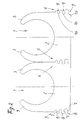
- clamps 1 are made of plastic shown, which is a base part 2 for fixed arrangement the clamp 1 and a fork-like clamping part with clamp arms 3 for clamping a pipe or the like.
- the base part 2 is in the essentially cuboid, the longer one Side face of the cuboid in the drawing in front and behind lies while the narrow side faces of the cuboid are directed orthogonally.
- the long Grooves 4 are formed on the side faces of the base part 2.
- the clamp 1 is with these grooves 4 on rails, for example plastic rails, can be slid across, which are profiled in a C-shape and those with their angled ends pointing towards each other engage corresponding grooves 4 of a clamp 1.
- the base part 4 On the base part 4 are parallel to the pipe bushing (parallel to the perpendicular to the drawing level according to Figure 1 for example) directed side surfaces Baying means 5, 6 for baying clamps 1 arranged with similarly designed baying means.
- the baying means 5, 6 consist of parallel to Pipe bushing of the clamping part, from a Side surface of the base part 2 protruding webs 7 with thickened ends 8 and on the other side surface of the base part formed grooves 9 with accordingly the web thickening extended groove base 10.
- Im Embodiment are on both side surfaces of the Base part 2 in sequence of grooves 9 and webs 7 with Thickenings 8 or extensions 10 are provided.
- the Bridge cross section different and the cross section the thickening 8 at the web ends analogous to the web cross sections is designed differently.
- the groove width corresponding to the Web measurement decreases and its extension 10 also decreases according to the thickening dimension.
- the stringing of such clamps 1 can both by Threading and moving the adjacent clamps 1 in the direction parallel to the course of a jammed Tube or the like take place as well as by transverse displacement of two aligned parallel to each other Clamps towards each other.
- the Mouths of the grooves 9 are shaped as well how the thickenings 8 towards their free end are tapered to provide an introducer when connecting the baying devices.
- both are Side surfaces of the base 2 each with webs 7 Thickenings 8 and grooves 9 with extensions 10 alternately trained one above the other.
- the arrangement and Formation of the grooves 9 with extensions 10 and webs 7 with thickenings 8 is made so that their cross-sectional dimension from the base surface (in the drawing figure 1 and 2 below) of the base part 2 to which the Clamping part bearing base surface decreases.
- the webs 7 with thickenings 8 and the grooves 9 with Extensions 10 are in the embodiment according to Figure 1 formed like a mushroom head.
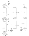
- the Embodiment according to Figures 2 to 8 are Thickenings 8 of the webs 7 and the extensions 10 of the grooves 9 shaped like a circular arc in cross section.
- the Web 7 with thickenings 8 are arranged so that between adjacent webs 7 with 8 thickening the mutually facing web flanks and Corresponding grooves 9 with corresponding thickening flanks Extensions 10 are shaped.
Description
Die Erfindung betrifft eine Klemmschelle siehe z.B. die US-A-4 306 697 und die EP-A-555550, insbesondere aus Kunststoff, mit einem Sockelteil zur ortsfesten Anordnung der Klemmschelle und einem gabelähnlichen Klemmteil mit Klemmarmen oder dergleichen Klemmelementen zum Einklemmen eines Rohres oder eines ähnlichen zylindrischen Langformteiles, wobei am Sockelteil an den parallel zur Rohrdurchführung des Klemmteils gerichteten Seitenflächen Anreihmittel zum Anreihen von Klemmschellen mit gleichartig ausgebildeten Anreihmitteln ausgebildet sind, wobei Anreihmittel aus parallel zur Rohrdurchführung des Klemmteiles verlaufenden, von einer Seitenfläche des Sockelteils abragenden Stegen mit verdickten Enden und aus in der anderen Seitenfläche des Sockelteils ausgebildeten Nuten mit entsprechend der Stegverdickung erweitertem Nutgrund bestehen.The invention relates to a clamp see e.g. US-A-4 306 697 and EP-A-555550 in particular made of plastic, with a base part for stationary Arrangement of the clamp and a fork-like Clamping part with clamping arms or similar clamping elements for clamping a pipe or the like cylindrical long molded part, with the base part parallel to the pipe duct of the clamping part aligned side surfaces of clamps with similarly designed baying devices are formed, with baying means from parallel for pipe passage of the clamping part, from one side surface of the base part projecting webs with thickened ends and out in the other side surface of the base part formed with grooves accordingly of the thickening of the web there is an enlarged groove base.
Bei einer derartigen Klemmschelle ist das Sockelteil etwa quaderförmig ausgebildet. Die längeren Seitenflächen des Sockelteils sind quer zur Verlaufsrichtung eines eingespannten Rohres oder dergleichen gerichtet, während die schmalen Sockelseiten parallel dazu gerichtet sind. Die schmalen Sockelseiten weisen die Anreihmittel auf, wobei in der einen Schmalseite eine Nut und an der anderen Schmalseite ein Vorsprung ausgebildet ist. Die Nut ist an ihren Enden, die aus den breiten Sockelflächen austreten offen. Der Steg verläuft über die gesamte Breite des schmalen Sockelteils. Die Nut ist dabei im Nutgrund mit einer Erweiterung versehen, während der Steg an seinem freien Ende eine Verdickung aufweist. Die Ausbildung gestattet es, mehrere gleichartige Klemmschellen nebeneinander anzuordnen und miteinander zu verbinden, indem eine Parallelverschiebung der benachbarten Klemmschellen in der Weise erfolgt, daß die Nut einer anzureihenden Klemmschelle auf einen Steg einer schon verlegten Klemmschelle parallel zur Verlaufsrichtung eines eingespannten Rohres aufgeschoben wird. Zusätzlich können noch an den langen Seitenflächen des Sockelteiles nut- und stegartige Führungselemente ausgebildet sein, die ein Aufschieben (Queraufschieben) auf eine Installationsschiene oder dergleichen ermöglichen. Bei derartigen bekannten Klemmschellen ist es lediglich möglich, diese Klemmschellen durch Parallelverschiebung zueinander miteinander zum Zwecke der Anreihung zu verbinden. Manchmal ist es aber wegen eines geringen Einbauraumes erforderlich, eine solche Schelle quer zu einer schon bestehenden Schelle anzuordnen und einzubringen, wobei dann die Ankopplung durch Parallelverschiebung der Teile zueinander nicht möglich ist. Dies ist insbesondere dann von Nachteil, wenn solche Klemmschellen in Schienen eingeschoben sind, die quer zur Verlaufrichtung der einzuklemmenden Rohre gerichtet sind. Weiterhin ist nachteilig, daß bei der angegebenen Ausführungsform lediglich die Verbindung mittels eines Klemmsteges erforderlich ist, der in die entsprechende Nut eingeschoben wir. Aus Sicherheitsgründen wäre es nützlich, wenn eine Mehrfachverbindung in der Anreihposition vorliegen würde.With such a clamp, the base part is approximately cuboid. The longer side faces the base part are transverse to the direction of a clamped pipe or the like directed while the narrow base sides are parallel to it. The narrow base sides have the baying means, with a groove on one narrow side and on the other a projection is formed on the other narrow side. The The groove is at its ends, which is made of the wide plinth surfaces emerge openly. The footbridge runs across the entire Width of the narrow base part. The groove is in the Groove provided with an extension during the Web has a thickening at its free end. The training allows several similar clamps to be arranged side by side and to each other connect by a parallel displacement of the neighboring clamps in such a way that the groove of a clamp to be attached to a web an already installed clamp parallel to the direction a clamped tube is pushed on. In addition, the long side surfaces of the Base part groove and web-like guide elements be designed to be pushed (transverse sliding) on an installation rail or the like enable. In such known clamps it is only possible to use these clamps Parallel shift to each other for the purpose to connect the baying. But sometimes it's because a small installation space required, such Clamp across an existing clamp to arrange and introduce, then the coupling by moving the parts parallel to each other is possible. This is particularly disadvantageous if such clamps are inserted in rails, the transverse to the direction of the pipes to be clamped are directed. Another disadvantage is that the specified embodiment only the connection is required by means of a clamping web, which in the we inserted the corresponding groove. Out For security reasons, it would be useful if a multiple connection would be in the baying position.
Ausgehend von diesem Stand der Technik liegt der Erfindung die Aufgabe zugrunde, eine Klemmschelle gattunsgemäßer Art zu schaffen, bei der eine sichere Verbindung zweier benachbarter Klemmschellen in der Anreihposition gebildet ist und bei der ein Anreihen sowohl in der Weise möglich ist, daß die Klemmschellen parallel zueinander verschoben und die Anreihmittel miteinander in Eingriff gebracht werden als auch die Klemmschellen quer zueinander verschoben werden können und die Anreihmittel dabei miteinander in Eingriff gebracht werden können.Based on this state of the art Invention the task of a clamp to create a generic type in which a safe Connection of two adjacent clamps in the Baying position is formed and a baying is possible both in that the clamps moved parallel to each other and the baying means be engaged with each other as well Clamps can be moved across each other and the baying means in engagement with each other can be brought.
Zur Lösung dieser Aufgabe schlägt die Erfindung vor, daß an der mit Stegen versehenen Seitenfläche des Sockelteils mehrere Stege mit Abstand übereinander, parallel zueinander verlaufend ausgebildet sind, wobei der Stegquerschnitt unterschiedlich und der Querschnitt der Verdickungen analog den Stegquerschnitten unterschiedlich ausgebildet ist, und daß an der mit Nuten versehenen Seitenfläche des Sockelteils entsprechend unterschiedlich geformte Nuten ausgebildet sind, wobei in der Anreihposition benachbarter Klemmschellen sämtliche Verdickungen der Stege in sämtlichen Erweiterungen der Nutgründe passend eingreifen, mindestens aber die zum Trennen der angereihten Klemmschellen auf Zug belasteten Flächen von Verdickungen und Erweiterungen aneinander anliegen.To achieve this object, the invention proposes that on the side surface of the Base part several webs at a distance from each other, are parallel to each other, wherein the cross section of the web is different and the cross section the thickening analogous to the web cross-sections is formed differently, and that with the Grooved side surface of the base part correspondingly shaped grooves are, in the baying position of adjacent clamps all thickening of the webs in all Interact appropriately with extensions of the groove bases, but at least those for separating the clamps in line areas of thickened areas subject to tension and extensions are close to each other.
Durch die Mehrfachanordnung von Stegen mit Verdickungen und Nuten mit Erweiterungen ist eine hohe Lagesicherheit in der Anreihposition gewährleistet, da nicht nur ein einziges Anreihmittel sondern mehrere Anreihmittel gleichzeitig zur Fixierung in der Sollposition zur Verfügung stehen. Durch die unterschiedliche Abmessung der Stegquerschnitte, der Verdickungen und der entsprechenden Nuten wird die manuelle Verbindung der Klemmschellen miteinander erleichtert, wenn diese Klemmschellen einander quer zugeführt werden, so daß die mit Nuten und Stegen versehenen Seitenflächen des Sockels orthogonal einander zugeführt werden, beispielsweise dann, wenn solche Klemmschellen in Installationsschienen geführt sind, die quer zur Verlaufsrichtung der einzuklemmenden Rohre angeordnet sind. Es wird nämlich durch die unterschiedliche Stegabmessung und Verdickungsabmessung sowie die unterschiedliche Nutabmessung erreicht, daß die einzelnen Anreihmittel mit unterschiedlichem Kraftaufwand ineinander gedrängt werden können, so daß beim Andrücken einer solchen Klemmschelle an eine schon installierte Klemmschelle trotz der Mehrfachanordnung der Anreihmittel nur ein mäßiger Kraftaufwand erforderlich ist. Insbesondere durch die im Querschnitt unterschiedlich bemessenen Verdickungen ist es leichter möglich, die im Querschnitt gering bemessenen Verdickungen beim Einschieben in die entsprechenden Nuten elastisch zu verformen bzw. auch die Nut elastisch zu verformen, als bei den im Querschnitt dicker bemessenen Verdickungen der Fall ist, so daß trotz der Mehrfachanordnung der Anreihmittel eine relativ geringe Kraft zu manuellem Verbinden der Anreihmittel erforderlich ist.Due to the multiple arrangement of bars with thickening and grooves with extensions is a high level of positional security guaranteed in the baying position, since not only one single baying device but several baying devices at the same time for fixing in the target position To be available. Due to the different dimensions the web cross-sections, the thickening and the corresponding grooves will be the manual connection of the Clamps relieved each other when this Clamps are fed across each other so that the side surfaces of the Pedestals are fed orthogonally to each other, for example when such clamps in Installation rails are guided, which cross to Direction of the pipes to be clamped arranged are. It is because of the different Web measurement and thickening dimension as well as the different groove dimensions achieved that the individual Baying equipment with different effort can be pushed together so that when pressed such a clamp to an already installed one Clamp despite the multiple arrangement of the baying means only moderate effort is required. Especially due to the different in cross section dimensioned thickening it is easier to do that small thickening in cross section at Insert elastically into the corresponding grooves deform or also elastically deform the groove, than for the thickenings with a thicker cross section the case is, so that despite the multiple arrangement of Baying means a relatively low force to manual Connecting the baying means is required.
Zudem ist das Anreihen der Klemmschellen sowohl durch Einfädeln und Verschieben der benachbarten Klemmschellen in Richtung parallel zum Verlauf eines eingeklemmten Rohres oder dergleichen zylindrischen Langformteil als auch durch Querverschiebung von zwei parallel zueinander ausgerichteten Klemmschellen zueinander hin erfolgt.In addition, the lining up of the clamps is both through Threading and moving the adjacent clamps in the direction parallel to the course of a jammed Pipe or the like cylindrical long molded part as also by shifting two parallel to each other aligned clamps to each other.
Um das manuelle Eindrücken beim Queranreihen zu erleichtern ist zudem vorgesehen, daß die Nutmündungen sich erweiternd geformt sind.In order to manually push in the lateral rows facilitate is also provided that the groove mouths are expanding.
Aus dem gleichen Grunde ist bevorzugt vorgesehen, daß die Verdickungen sich zum freien Ende hin verjüngend geformt sind.For the same reason, it is preferably provided that the thickenings taper towards the free end are shaped.
Eine besonders bevorzugte und geeignete Weiterbildung wird darin gesehen, daß an beiden Seitenflächen des Sockels jeweils Stege mit Verdickungen und Nuten mit Erweiterungen jeweils abwechselnd übereinander ausgebildet sind.A particularly preferred and suitable further education is seen in the fact that on both sides of the Base with webs with thickening and grooves Extensions alternately one above the other are trained.
Hierdurch wird eine besonders haltbare Fixierung der Teile aneinander bewirkt und zudem bei geringem Platzbedarf am Sockelteil die Anordnung von mehreren Anreihmitteln ermöglicht.As a result, a particularly durable fixation of the Parts brought together and also takes up little space the arrangement of several baying devices on the base part enables.
Weiterhin ist bevorzugt vorgesehen, daß die Anordnung und Ausbildung der Nuten mit Erweiterungen und Stege mit Verdickungen so vorgenommen ist, daß deren Querschnittsabmessung von der Basisfläche des Sockelteils zu der das Klemmteil tragenden Sockelfläche hin abnimmt.Furthermore, it is preferably provided that the arrangement and formation of the grooves with extensions and webs is made with thickenings so that their Cross-sectional dimension from the base surface of the base part towards the base surface carrying the clamping part decreases.
Bei dieser Ausbildung ist beispielsweise der Steg mit Verdickungen, der in unmittelbarer Nähe der Basis des Sockelteils angeordnet ist, derjenige mit der größten Querschnittsabmessung und ebenso die dazugehörige Nut, während mit zunehmendem Abstand von der Basisfläche des Sockelteils in Richtung auf die Klemmarme des Sockelteils Stege mit geringerem Querschnitt, Verdickungen mit geringerem Querschnitt und entsprechend auch Nuten und Erweiterung mit geringerem Querschnitt ausgebildet sind. Dies ist insbesondere bei der Montage solcher Klemmschellen an quer zur Rohrverlaufrichtung oder dergleichen gerichteten Schlitzschienen vorteilhaft, weil die Klemmschellen in der Nähe des Sockelteiles durch die entsprechenden Schienen geführt sind, so daß beim Querverbinden und Zusammenstecken der Klemmschellen in diesem Bereich ein höherer Kraftaufwand aufbringbar ist, ohne daß die Neigung besteht, daß die Klemmschellen sich gegeneinander verschieben, während mit Abstand von der Basisfläche und gleichzeitigem entsprechend größerem Abstand von der Eingriffsstelle der Schiene der Kraftaufwand zum Verbinden der Anreihmittel geringer wird.In this training, for example, the web is included Thickening that is in close proximity to the base of the Base part is arranged, the one with the largest Cross-sectional dimension and also the associated groove, while increasing distance from the base surface of the base part in the direction of the clamping arms of the Base part webs with a smaller cross-section, Thickenings with a smaller cross-section and accordingly also grooves and extensions with a smaller cross-section are trained. This is especially true during assembly such clamps on transverse to the pipe direction or the like directed slot rails advantageous, because the clamps near the base part are guided through the corresponding rails, so that when connecting and plugging the clamps together a higher effort can be applied in this area is without the tendency that the clamps move against each other while at a distance from the base area and at the same time accordingly greater distance from the point of engagement of the rail the effort required to connect the baying means is lower becomes.
Eine unter Umständen bevorzugte Ausbildung wird darin gesehen, daß die Stege mit Verdickungen und die Nuten mit Erweiterungen im Querschnitt pilzkopfartig ausgebildet sind.A possibly preferred training is in it seen that the webs with thickening and the grooves with extensions in cross section mushroom-like are trained.
Hierdurch wird das Zusammenstecken der Klemmschellen weiterhin gefördert, wobei ein unbeabsichtiges Ausrasten der in Eingriff befindlichen Stegverdickungen und Nuterweiterungen wegen der pilzkopfartigen Ausbildung von Verdickungen und Nuterweiterungen auszuschließen ist, da durch die vorzugsweise rechtwinklig zur Zuführrichtung der Klemmschellen Anreihmittel ausgerichteten Hinterschnittflächen der pilzkopfartigen Ausbildung eine nahezu unlösbare Rastverbindung gebildet ist.This will put the clamps together continued to be promoted, with an unintentional freaking out the engaging web thickenings and groove extensions because of the mushroom-like formation of Thickening and widening of the groove must be excluded because by preferably at right angles to the feed direction aligned with the clamps Undercut surfaces of the mushroom-like formation an almost undetachable locking connection is formed.
Alternativ kann auch bevorzugt sein, daß die Verdickungen der Stege und die Erweiterungen der Nuten im Querschnitt kreisbogenartig geformt sind.Alternatively, it can also be preferred that the thickenings the webs and the extensions of the grooves in cross section are shaped like a circular arc.
Um auf geringem Raum (bei geringer Höhe des Sockelteils) möglichst viele Anreihmittel unterbringen zu können, ist zudem vorgesehen, daß die Stege mit Verdickungen so angeordnet sind, daß zwischen benachbarten Stegen mit Verdickungen durch die einander zugewandten Stegflanken und Verdickungsflanken entsprechende Nuten mit Erweiterungen geformt sind.In a small space (with a low height of the base part) to be able to accommodate as many baying aids as possible, it is also provided that the webs with thickenings are arranged so that between adjacent webs with thickened areas facing each other Grooves and thickening flanks corresponding grooves are shaped with extensions.
Um die Montage beim Zusammenführen der durch Querbewegung zueinander zu verbindenden Anreihmittel noch zu erleichtern ist zudem vorgesehen, daß die einander benachbarten Stege mit Verdickungen und Nuten mit Erweiterungen so ausgebildet sind, daß beim Querzuführen einer weiteren Klemmschelle zunächst die im Querschnitt am größten bemessenen Verdickungen in die am größten bemessenen Nuten mit Erweiterungen teilweise eindrückbar sind bevor die im Querschnitt nächst kleinere Verdickung in die zugehörige Nut eingreift.To assemble when merging by transverse movement to be connected to each other It is also envisaged that each other neighboring webs with thickening and grooves Extensions are designed so that when lateral guidance Another clamp first in cross section largest thickened in the largest dimensioned grooves with extensions partially depressible are before the next smallest thickening in cross section engages in the associated groove.
Beispielsweise können die im Querschnitt größeren Verdickungen weiter über die Seitenflucht des Sockelteils vorragen als die im Querschnitt geringer bemessenen Verdickungen, so daß beim Zusammenführen benachbarter Klemmschellen zunächst die im Querschnitt größer bemessenen Verdickungen in die entsprechenden Nuten teilweise eingreifen, bevor die nächst größere Verdickung eines benachbarten Steges in die entsprechend bemessene weitere Nut eingreift und infolge dann das oder die weiteren im Querschnitt geringer bemessenen Verdickungen an den Stegenden in die entsprechenden Nuten nachfolgend eingreifen. Auf diese Weise wird bei der Montage eine gewisse Kraftverteilung erreicht, was für den Montagevorgang vorteilhaft ist. For example, the larger ones in cross section Thickenings continue over the side alignment of the base part protrude than the smaller in cross section Thickening, so that when merging neighboring Clamps are initially larger in cross section dimensioned thickenings in the corresponding grooves partially intervene before the next larger thickening of a neighboring bridge into the correspondingly dimensioned one engages another groove and as a result then that or further thickenings with smaller cross-sections at the web ends in the corresponding grooves below intervention. In this way, a certain power distribution reached what for the assembly process is advantageous.
Ausführungsbeispiele der Erfindung sind in der Zeichnung
gezeigt und im folgenden näher beschrieben.
Es zeigt:
- Fig. 1
- eine erste Ausführungsform von Klemmschellen in Ansicht;
- Fig. 2
- eine Variante in gleicher Ansicht;
- Fig. 3 bis 8
- Detaildarstellungen der Variante gemäß
Figur 2 in unterschiedlicher Montageposition.
It shows:
- Fig. 1
- a first embodiment of clamps in view;
- Fig. 2
- a variant in the same view;
- 3 to 8
- Detailed representations of the variant according to Figure 2 in different mounting position.
In den Zeichnungen sind Klemmschellen 1 aus Kunststoff
gezeigt, die ein Sockelteil 2 zur ortsfesten Anordnung
der Klemmschelle 1 und ein gabelähnliches Klemmteil
mit Klemmarmen 3 zum Einklemmen eines Rohres oder
dergleichen aufweisen. Das Sockelteil 2 ist im
wesentlichen quaderförmig ausgebildet, wobei die längere
Seitenfläche des Quaders in der Zeichnung vorn und hinten
liegt, während die schmalen Seitenflächen des Quaders
orthogonal dazu gerichtet sind. In den langen
Seitenflächen des Sockelteils 2 sind Nuten 4 ausgebildet.
Die Klemmschelle 1 ist mit diesen Nuten 4 auf Schienen,
beispielsweise Kunststoffschienen, quer aufschiebbar,
die C-förmig profiliert sind und die mit ihren
abgewinkelten zueinander weisenden Enden in die
entsprechenden Nuten 4 einer Klemmschelle 1 eingreifen.In the drawings,
Am Sockelteil 4 sind an den parallel zur Rohrdurchführung
(parallel zur Lotrechten auf die Zeichnungsebene gemäß
Figur 1 beispielsweise) gerichteten Seitenflächen
Anreihmittel 5, 6 zum Anreihen von Klemmschellen 1
mit gleichartig ausgebildeten Anreihmitteln angeordnet.
Die Anreihmittel 5, 6 bestehen aus parallel zur
Rohrdurchführung des Klemmteils verlaufenden, von einer
Seitenfläche des Sockelteils 2 abragenden Stegen 7 mit
verdickten Enden 8 und auf der anderen Seitenfläche
des Sockelteils ausgebildeten Nuten 9 mit entsprechend
der Stegverdickung erweitertem Nutgrund 10. Im
Ausführungsbeispiel sind an beiden Seitenflächen des
Sockelteils 2 in Abfolge Nuten 9 und Stege 7 mit
Verdickungen 8 bzw. Erweiterungen 10 vorgesehen. An
der mit Stegen 7 versehenen Seitenfläche des Sockelteils
2 sind mehrere Stege 7 mit Abstand übereinander, parallel
zueinander verlaufend ausgebildet, wobei der
Stegquerschnitt unterschiedlich und der Querschnitt
der Verdickungen 8 an den Stegenden analog den Stegquerschnitten
unterschiedlich ausgebildet ist. An der
mit den Nuten 9 versehenen Seitenfläche des Sockelteils
2 sind entsprechend unterschiedlich geformte Nuten
ausgebildet, deren Nutweite entsprechend der
Stegabmessung abnimmt und deren Erweiterung 10 ebenfalls
entsprechend der Verdickungsabmessung abnimmt.On the
In der Anreihposition, die beispielsweise in Figur 1
und 2 gezeigt ist, sind sämtliche Verdickungen 8 der
Stege 7 in sämtlichen Erweiterungen 10 der Nutgründe
der Nuten 9 passend eingefügt. Insbesondere bei der
Ausführungsform gemäß Figur 1 sind die zum Trennen der
angereihten Klemmschellen 1 auf Zug belasteten Flächen 11
der Verdickungen 8 und der Erweiterungen 10 in der
Anreihposition aneinander anliegend, während zwischen
dem freien Ende der Verdickung und dem Nutgrund in der
Erweiterung 10 ein gewisses Spiel vorhanden ist.In the baying position, for example in FIG. 1
and FIG. 2, all of the
Das Anreihen solcher Klemmschellen 1 kann sowohl durch
Einfädeln und Verschieben der benachbarten Klemmschellen
1 in Richtung parallel zum Verlauf eines eingeklemmten
Rohres oder dergleichen erfolgen als auch durch Querverschiebung
von zwei parallel zueinander ausgerichteten
Klemmschellen zueinander hin. Vorzugsweise sind die
Mündungen der Nuten 9 sich erweiternd geformt ebenso
wie die Verdickungen 8 sich zu ihrem freien Ende hin
verjüngend geformt sind, um auf diese Weise eine Einführhilfe
beim Verbinden der Anreihmittel zu erreichen.The stringing of
Bei den dargestellten Ausführungsformen sind an beiden
Seitenflächen des Sockels 2 jeweils Stege 7 mit
Verdickungen 8 und Nuten 9 mit Erweiterungen 10
abwechseln übereinander ausgebildet. Die Anordnung und
Ausbildung der Nuten 9 mit Erweiterungen 10 und Stege
7 mit Verdickungen 8 ist so vorgenommen, daß deren Querschnittsabmessung
von der Basisfläche (in Zeichnungsfigur
1 und 2 unten) des Sockelteils 2 zu der das
Klemmteil tragenden Sockelfläche hin abnimmt.In the illustrated embodiments, both are
Side surfaces of the
Die Stege 7 mit Verdickungen 8 und die Nuten 9 mit
Erweiterungen 10 sind bei der Ausführungsformg gemäß
Figur 1 pilzkopfartig ausgebildet. Bei der
Ausführungsform gemäß Figur 2 bis 8 sind die
Verdickungen 8 der Stege 7 und die Erweiterungen 10
der Nuten 9 im Querschnitt kreisbogenartig geformt.
Um eine räumlich äußerst enge Anordnung von möglichst
vielen Stegen und Nuten zu ermöglichen und somit die
zur Verfügung stehende Fläche des Sockelteil 2 möglichst
vollständig zu nutzen, ist zudem vorgesehen, daß die
Stege 7 mit Verdickungen 8 so angeordnet sind, daß
zwischen benachbarten Stegen 7 mit Verdickungen 8 durch
die einander zugewandten Stegflanken und
Verdickungsflanken entsprechende Nuten 9 mit
Erweiterungen 10 geformt sind.The
Bei der Ausführungsform gemäß Figur 2 bis 8 sind die
einander benachbarten Stege 7 mit Verdickungen 8 und
Nuten 9 mit Erweiterungen 10 so ausgebildet, daß beim
Querzuführen einer weiteren Klemmschelle 1 zu einer
vorhandenen Klemmschelle 1 zunächst die im Querschnitt
am größten bemessenen Verdickungen 8 in die am größten
bemessenen Nuten 9 mit Erweiterungen 10 teilweise
eindrückbar sind, bevor die im Querschnitt nächst
kleinere Verdickung 8 in die zugehörige Nut 9 eingreift.
Der entsprechende Bewegungsablauf bei dem Querzuführen
von zwei Klemmschellen ist anhand der Figuren 3 bis
8 erläutert. In Figur 3 ist zunächst beispielsweise
die links dargestellt Klemmschelle 1 schon fest
installiert, während die rechts dargestellte Klemmschelle
1 dieser quer zugeführt wird. Gemäß Figur 4 erfolgt
bei einer Annäherung der beiden Klemmschellen 7
zueinander zunächst ein Eingriff der im Querschnitt
am größten bemessenen Verdickung 8 (jeweils an der
Klemmschelle unten) in die im Querschnitt am größten
bemessene Nut 9 mit entsprechender Verdickung 10. Dies
ist aus Figur 4 ersichtlich. Bei weiterem Annähern der
Klemmschellen 1 erfolgt dann ein Eingriff der nächst
größeren Verdickung 8 in die entsprechende Nut 9, so
daß gemäß Figur 5 zunächst die unteren beiden
Anreihmittel miteinander in Kontakt sind. Gemäß Figur
6 erfolgt bei weiterer Annäherung der Klemmschellen
1 aneinander dann auch ein Eingriff der nächstfolgenden
geringer bemessenen Verdickung 8 in die entsprechende
Nut 9, bis gemäß Figur 7 alle Verdickungen 8 in die
entsprechenden Nuten 9 eingreifen. In der Sollposition,
die in Figur 8 gezeigt ist, sitzen dann die Verdickungen
8 in den entsprechenden Erweiterungen 10 der Nuten 11
passend ein.In the embodiment according to Figures 2 to 8 are the
mutually
Auf diese Weise wird eine Kraftverteilung beim Zuführen
der Klemmschellen 1 erreicht, so daß der Montagevorgang
noch zunehmend erleichtert wird.In this way, a force distribution when feeding
the
Claims (9)
- A clamp strap, in particular made from plastic material, having a base part for the fixed arrangement of the clamp strap and a fork-like clamping part with clamping arms or similar clamping elements for clamping a pipe or a similar cylindrical oblong part, attachment means for the attachment of clamp straps having attachment means of a similar design being constructed at the base part at the side faces directed parallel to the tubular feedthrough of the clamping part, the attachment means consisting of webs, with thickened ends, which extend parallel to the tubular feedthrough of the clamping part and project from one side face of the base part, and of grooves, with groove bases widened to correspond with the thickened portion of the web, which are constructed in the other side face of the base part,
characterised in that on the side face of the base part (2) provided with webs (7), several webs (7) are constructed so that they are spaced one above the other and extend parallel to one another, the cross section the webs varying and the cross section of the thickened portions (8) varying similarly to the web cross sections,
and in that on the side face of the base part (2) provided with grooves (9), grooves (9) having different shapes are correspondingly constructed, in the attached position of adjacent clamp straps (1) all thickened portions (8) of the webs (7) engaging tightly in all widened portions (10) of the groove bases, but at least the faces (11) of thickened portions (8) and widened portions (10), which are under tension for the separation of the attached clamp straps (1), abut one another. - A clamp strap according to Claim 1,
characterised in that the groove openings are shaped so that they widen. - A clamp strap according to Claim 1 or 2,
characterised in that the thickened portions (8) are shaped so that they taper towards the free end. - A clamp strap according to one of Claims 1 to 3,
characterised in that at both side faces of the base (2), webs (7) having thickened portions (8) and grooves (9) having widened portions (19) respectively are constructed alternately one above the other. - A clamp strap according to one of Claims 1 to 4,
characterised in that the arrangement and construction of the grooves (9) with widened portions (10) and webs (7) with thickened portions (8) is performed so that their cross-sectional dimension decreases from the bottom face of the base part (2) to the base face bearing the clamping part. - A clamp strap according to one of Claims 1 to 5,
characterised in that the webs (7) having thickened portions (8) and the grooves (9) having widened portions (10) are constructed with a cross section in the manner of a mushroom head. - A clamp strap according to one of Claims 1 to 5,
characterised in that the thickened portions (8) of the webs (7) and the widened portions (10) of the grooves (9) are shaped so that they have a circular arc cross-section. - A clamp strap according to one of Claims 1 to 7,
characterised in that the webs (7) having thickened portions (8) are disposed so that, between adjacent webs (7) having thickened portions (8), corresponding grooves (9) having widened portions (10) are formed by the faces of the webs and faces of the thickened portions that face one another. - A clamp strap according to one of Claims 1 to 8,
characterised in that the mutually adjacent webs (7) having thickened portions (8) and grooves (9) having widened portions (10) are constructed so that, during the transversal supply of another clamp strap (1), first of all the grooves (9), having widened portions (10), which have the largest cross section can be partly forced in before the thickened portion (8) having the next smaller cross section engages in the associated groove (9).
Applications Claiming Priority (2)
| Application Number | Priority Date | Filing Date | Title |
|---|---|---|---|
| DE19609440 | 1996-03-11 | ||
| DE19609440A DE19609440C1 (en) | 1995-11-01 | 1996-03-11 | Plastics collar band for pipes |
Publications (3)
| Publication Number | Publication Date |
|---|---|
| EP0795708A2 EP0795708A2 (en) | 1997-09-17 |
| EP0795708A3 EP0795708A3 (en) | 1999-06-09 |
| EP0795708B1 true EP0795708B1 (en) | 2001-04-18 |
Family
ID=7787902
Family Applications (1)
| Application Number | Title | Priority Date | Filing Date |
|---|---|---|---|
| EP19960112410 Expired - Lifetime EP0795708B1 (en) | 1996-03-11 | 1996-08-01 | Pipe clamp |
Country Status (3)
| Country | Link |
|---|---|
| EP (1) | EP0795708B1 (en) |
| ES (1) | ES2157375T3 (en) |
| PT (1) | PT795708E (en) |
Families Citing this family (2)
| Publication number | Priority date | Publication date | Assignee | Title |
|---|---|---|---|---|
| EP1746321A1 (en) | 2005-07-22 | 2007-01-24 | IMET S.r.l. | Fastening device for cylindrical bodies, especially tubes and cables |
| NL2022976B1 (en) * | 2019-04-18 | 2020-10-26 | Hemmink B V | Saddle clamp |
Family Cites Families (3)
| Publication number | Priority date | Publication date | Assignee | Title |
|---|---|---|---|---|
| US4306697A (en) * | 1980-06-16 | 1981-12-22 | Mathews Lyle H | Conduit spacer system |
| DE9201892U1 (en) * | 1992-02-14 | 1992-04-02 | Hermann Kleinhuis Gmbh & Co Kg, 5880 Luedenscheid, De | |
| DE9314862U1 (en) * | 1993-09-30 | 1994-01-20 | Reiku Gmbh | Holder system for pipes or the like |
-
1996
- 1996-08-01 ES ES96112410T patent/ES2157375T3/en not_active Expired - Lifetime
- 1996-08-01 PT PT96112410T patent/PT795708E/en unknown
- 1996-08-01 EP EP19960112410 patent/EP0795708B1/en not_active Expired - Lifetime
Also Published As
| Publication number | Publication date |
|---|---|
| PT795708E (en) | 2001-07-31 |
| EP0795708A2 (en) | 1997-09-17 |
| ES2157375T3 (en) | 2001-08-16 |
| EP0795708A3 (en) | 1999-06-09 |
Similar Documents
| Publication | Publication Date | Title |
|---|---|---|
| DE2647235C2 (en) | Spacer for pipes passed through protective pipes | |
| EP0449910B1 (en) | Quick-action connecting device | |
| EP2142823A1 (en) | Side wall segment for a cable guide device, cable guide device having a side wall segment, and method for producing the side wall segment | |
| DE4434202A1 (en) | Cable lead-through strip | |
| DE2431679A1 (en) | PIPE CONNECTOR IN ELEMENTAL DESIGN | |
| WO2010145744A1 (en) | Profile bar connection system | |
| DE3516448C1 (en) | Energy-guidance chain | |
| DE4121433C1 (en) | ||
| DE19820651B4 (en) | Cable guide assembly with a zugentlastenden attachment of at least one guided in the wiring guide line | |
| EP3649711A1 (en) | Cable guiding means for arrangement on a profiled bar | |
| DE3838957C2 (en) | ||
| DE2504476B2 (en) | Connecting link for connecting two profile bars running perpendicular to one another | |
| DE19609440C1 (en) | Plastics collar band for pipes | |
| EP0795708B1 (en) | Pipe clamp | |
| DE3903950C2 (en) | ||
| DE102019101180A1 (en) | holder | |
| EP1229282B1 (en) | Adaptor for the mounting of clamping collar | |
| DE4312340C2 (en) | Dowels | |
| EP1516129B1 (en) | Linear roller bearing | |
| DE19719013C2 (en) | With a wall bracket, cross-sectionally U-shaped holding profile for a partition | |
| EP0693638A1 (en) | Chain for carrying an energy line and method of introducing the line in the chain | |
| DE19615144C2 (en) | Connection of a base of a cable distribution cabinet with its structure | |
| DE2907850C2 (en) | Pipe clamp | |
| DE3734875C2 (en) | ||
| DE19817427A1 (en) | Gripping connector for releasable connection between hollow sections |
Legal Events
| Date | Code | Title | Description |
|---|---|---|---|
| PUAI | Public reference made under article 153(3) epc to a published international application that has entered the european phase |
Free format text: ORIGINAL CODE: 0009012 |
|
| AK | Designated contracting states |
Kind code of ref document: A2 Designated state(s): BE ES IT LU NL PT |
|
| PUAL | Search report despatched |
Free format text: ORIGINAL CODE: 0009013 |
|
| AK | Designated contracting states |
Kind code of ref document: A3 Designated state(s): BE ES IT LU NL PT |
|
| 17P | Request for examination filed |
Effective date: 19990617 |
|
| RAP1 | Party data changed (applicant data changed or rights of an application transferred) |
Owner name: OBO BETTERMANN GMBH & CO. KG. |
|
| GRAG | Despatch of communication of intention to grant |
Free format text: ORIGINAL CODE: EPIDOS AGRA |
|
| GRAG | Despatch of communication of intention to grant |
Free format text: ORIGINAL CODE: EPIDOS AGRA |
|
| GRAH | Despatch of communication of intention to grant a patent |
Free format text: ORIGINAL CODE: EPIDOS IGRA |
|
| 17Q | First examination report despatched |
Effective date: 20001012 |
|
| GRAH | Despatch of communication of intention to grant a patent |
Free format text: ORIGINAL CODE: EPIDOS IGRA |
|
| GRAA | (expected) grant |
Free format text: ORIGINAL CODE: 0009210 |
|
| AK | Designated contracting states |
Kind code of ref document: B1 Designated state(s): BE ES IT LU NL PT |
|
| ITF | It: translation for a ep patent filed |
Owner name: MODIANO & ASSOCIATI S.R.L. |
|
| REG | Reference to a national code |
Ref country code: PT Ref legal event code: SC4A Free format text: AVAILABILITY OF NATIONAL TRANSLATION Effective date: 20010424 |
|
| PG25 | Lapsed in a contracting state [announced via postgrant information from national office to epo] |
Ref country code: LU Free format text: LAPSE BECAUSE OF EXPIRATION OF PROTECTION Effective date: 20010801 |
|
| REG | Reference to a national code |
Ref country code: ES Ref legal event code: FG2A Ref document number: 2157375 Country of ref document: ES Kind code of ref document: T3 |
|
| PLBE | No opposition filed within time limit |
Free format text: ORIGINAL CODE: 0009261 |
|
| STAA | Information on the status of an ep patent application or granted ep patent |
Free format text: STATUS: NO OPPOSITION FILED WITHIN TIME LIMIT |
|
| 26N | No opposition filed | ||
| PGFP | Annual fee paid to national office [announced via postgrant information from national office to epo] |
Ref country code: NL Payment date: 20140820 Year of fee payment: 19 |
|
| PGFP | Annual fee paid to national office [announced via postgrant information from national office to epo] |
Ref country code: ES Payment date: 20140826 Year of fee payment: 19 |
|
| PGFP | Annual fee paid to national office [announced via postgrant information from national office to epo] |
Ref country code: PT Payment date: 20140203 Year of fee payment: 19 Ref country code: IT Payment date: 20140828 Year of fee payment: 19 |
|
| PGFP | Annual fee paid to national office [announced via postgrant information from national office to epo] |
Ref country code: BE Payment date: 20140820 Year of fee payment: 19 |
|
| REG | Reference to a national code |
Ref country code: PT Ref legal event code: MM4A Free format text: LAPSE DUE TO NON-PAYMENT OF FEES Effective date: 20160201 |
|
| PG25 | Lapsed in a contracting state [announced via postgrant information from national office to epo] |
Ref country code: IT Free format text: LAPSE BECAUSE OF NON-PAYMENT OF DUE FEES Effective date: 20150801 |
|
| REG | Reference to a national code |
Ref country code: NL Ref legal event code: MM Effective date: 20150901 |
|
| PG25 | Lapsed in a contracting state [announced via postgrant information from national office to epo] |
Ref country code: PT Free format text: LAPSE BECAUSE OF NON-PAYMENT OF DUE FEES Effective date: 20160201 |
|
| PG25 | Lapsed in a contracting state [announced via postgrant information from national office to epo] |
Ref country code: NL Free format text: LAPSE BECAUSE OF NON-PAYMENT OF DUE FEES Effective date: 20150901 |
|
| REG | Reference to a national code |
Ref country code: ES Ref legal event code: FD2A Effective date: 20160927 |
|
| PG25 | Lapsed in a contracting state [announced via postgrant information from national office to epo] |
Ref country code: ES Free format text: LAPSE BECAUSE OF NON-PAYMENT OF DUE FEES Effective date: 20150802 Ref country code: PT Free format text: LAPSE BECAUSE OF EXPIRATION OF PROTECTION Effective date: 20160809 |
|
| PG25 | Lapsed in a contracting state [announced via postgrant information from national office to epo] |
Ref country code: BE Free format text: LAPSE BECAUSE OF NON-PAYMENT OF DUE FEES Effective date: 20150831 Ref country code: PT Free format text: LAPSE BECAUSE OF EXPIRATION OF PROTECTION Effective date: 20160208 |