EP0795702B1 - Dichtung mit eingebetteter Ringfeder - Google Patents
Dichtung mit eingebetteter Ringfeder Download PDFInfo
- Publication number
- EP0795702B1 EP0795702B1 EP97301539A EP97301539A EP0795702B1 EP 0795702 B1 EP0795702 B1 EP 0795702B1 EP 97301539 A EP97301539 A EP 97301539A EP 97301539 A EP97301539 A EP 97301539A EP 0795702 B1 EP0795702 B1 EP 0795702B1
- Authority
- EP
- European Patent Office
- Prior art keywords
- seal
- spring
- lip body
- mold
- garter spring
- Prior art date
- Legal status (The legal status is an assumption and is not a legal conclusion. Google has not performed a legal analysis and makes no representation as to the accuracy of the status listed.)
- Expired - Lifetime
Links
- 230000036316 preload Effects 0.000 claims abstract description 12
- 239000012530 fluid Substances 0.000 claims abstract description 11
- 229920001971 elastomer Polymers 0.000 claims description 19
- 238000000034 method Methods 0.000 claims description 9
- 238000000465 moulding Methods 0.000 claims description 8
- 239000000806 elastomer Substances 0.000 claims description 7
- 238000005304 joining Methods 0.000 claims description 3
- 230000015572 biosynthetic process Effects 0.000 claims description 2
- 239000013536 elastomeric material Substances 0.000 claims 2
- 238000004519 manufacturing process Methods 0.000 description 5
- 230000000694 effects Effects 0.000 description 4
- 230000001965 increasing effect Effects 0.000 description 2
- 239000000463 material Substances 0.000 description 2
- 229910000831 Steel Inorganic materials 0.000 description 1
- 238000000429 assembly Methods 0.000 description 1
- 230000000712 assembly Effects 0.000 description 1
- 230000002708 enhancing effect Effects 0.000 description 1
- 238000003825 pressing Methods 0.000 description 1
- 230000000135 prohibitive effect Effects 0.000 description 1
- 230000000717 retained effect Effects 0.000 description 1
- 239000010959 steel Substances 0.000 description 1
Images


Classifications
-
- B—PERFORMING OPERATIONS; TRANSPORTING
- B29—WORKING OF PLASTICS; WORKING OF SUBSTANCES IN A PLASTIC STATE IN GENERAL
- B29C—SHAPING OR JOINING OF PLASTICS; SHAPING OF MATERIAL IN A PLASTIC STATE, NOT OTHERWISE PROVIDED FOR; AFTER-TREATMENT OF THE SHAPED PRODUCTS, e.g. REPAIRING
- B29C45/00—Injection moulding, i.e. forcing the required volume of moulding material through a nozzle into a closed mould; Apparatus therefor
- B29C45/14—Injection moulding, i.e. forcing the required volume of moulding material through a nozzle into a closed mould; Apparatus therefor incorporating preformed parts or layers, e.g. injection moulding around inserts or for coating articles
- B29C45/14065—Positioning or centering articles in the mould
-
- F—MECHANICAL ENGINEERING; LIGHTING; HEATING; WEAPONS; BLASTING
- F16—ENGINEERING ELEMENTS AND UNITS; GENERAL MEASURES FOR PRODUCING AND MAINTAINING EFFECTIVE FUNCTIONING OF MACHINES OR INSTALLATIONS; THERMAL INSULATION IN GENERAL
- F16J—PISTONS; CYLINDERS; SEALINGS
- F16J15/00—Sealings
- F16J15/16—Sealings between relatively-moving surfaces
- F16J15/32—Sealings between relatively-moving surfaces with elastic sealings, e.g. O-rings
- F16J15/3204—Sealings between relatively-moving surfaces with elastic sealings, e.g. O-rings with at least one lip
- F16J15/3208—Sealings between relatively-moving surfaces with elastic sealings, e.g. O-rings with at least one lip provided with tension elements, e.g. elastic rings
-
- F—MECHANICAL ENGINEERING; LIGHTING; HEATING; WEAPONS; BLASTING
- F16—ENGINEERING ELEMENTS AND UNITS; GENERAL MEASURES FOR PRODUCING AND MAINTAINING EFFECTIVE FUNCTIONING OF MACHINES OR INSTALLATIONS; THERMAL INSULATION IN GENERAL
- F16J—PISTONS; CYLINDERS; SEALINGS
- F16J15/00—Sealings
- F16J15/16—Sealings between relatively-moving surfaces
- F16J15/32—Sealings between relatively-moving surfaces with elastic sealings, e.g. O-rings
- F16J15/3204—Sealings between relatively-moving surfaces with elastic sealings, e.g. O-rings with at least one lip
- F16J15/3208—Sealings between relatively-moving surfaces with elastic sealings, e.g. O-rings with at least one lip provided with tension elements, e.g. elastic rings
- F16J15/3212—Sealings between relatively-moving surfaces with elastic sealings, e.g. O-rings with at least one lip provided with tension elements, e.g. elastic rings with metal springs
-
- F—MECHANICAL ENGINEERING; LIGHTING; HEATING; WEAPONS; BLASTING
- F16—ENGINEERING ELEMENTS AND UNITS; GENERAL MEASURES FOR PRODUCING AND MAINTAINING EFFECTIVE FUNCTIONING OF MACHINES OR INSTALLATIONS; THERMAL INSULATION IN GENERAL
- F16J—PISTONS; CYLINDERS; SEALINGS
- F16J15/00—Sealings
- F16J15/16—Sealings between relatively-moving surfaces
- F16J15/32—Sealings between relatively-moving surfaces with elastic sealings, e.g. O-rings
- F16J15/328—Manufacturing methods specially adapted for elastic sealings
-
- B—PERFORMING OPERATIONS; TRANSPORTING
- B29—WORKING OF PLASTICS; WORKING OF SUBSTANCES IN A PLASTIC STATE IN GENERAL
- B29L—INDEXING SCHEME ASSOCIATED WITH SUBCLASS B29C, RELATING TO PARTICULAR ARTICLES
- B29L2031/00—Other particular articles
- B29L2031/26—Sealing devices, e.g. packaging for pistons or pipe joints
-
- Y—GENERAL TAGGING OF NEW TECHNOLOGICAL DEVELOPMENTS; GENERAL TAGGING OF CROSS-SECTIONAL TECHNOLOGIES SPANNING OVER SEVERAL SECTIONS OF THE IPC; TECHNICAL SUBJECTS COVERED BY FORMER USPC CROSS-REFERENCE ART COLLECTIONS [XRACs] AND DIGESTS
- Y10—TECHNICAL SUBJECTS COVERED BY FORMER USPC
- Y10S—TECHNICAL SUBJECTS COVERED BY FORMER USPC CROSS-REFERENCE ART COLLECTIONS [XRACs] AND DIGESTS
- Y10S277/00—Seal for a joint or juncture
- Y10S277/924—Deformation, material removal, or molding for manufacture of seal
-
- Y—GENERAL TAGGING OF NEW TECHNOLOGICAL DEVELOPMENTS; GENERAL TAGGING OF CROSS-SECTIONAL TECHNOLOGIES SPANNING OVER SEVERAL SECTIONS OF THE IPC; TECHNICAL SUBJECTS COVERED BY FORMER USPC CROSS-REFERENCE ART COLLECTIONS [XRACs] AND DIGESTS
- Y10—TECHNICAL SUBJECTS COVERED BY FORMER USPC
- Y10S—TECHNICAL SUBJECTS COVERED BY FORMER USPC CROSS-REFERENCE ART COLLECTIONS [XRACs] AND DIGESTS
- Y10S425/00—Plastic article or earthenware shaping or treating: apparatus
- Y10S425/047—Seal ring
Definitions
- the present invention relates generally to improved fluid seal assemblies, methods and apparatus for manufacturing fluid seals.
- the methods and apparatus overcome problems with well-known prior art seals having so-called embedded garter springs within the lip body portions of fluid seals, i.e., a seal having a casing as well as an elastomeric seal lip body.
- a garter spring augments the radial load provided by the resiliency of the seal lip.
- the spring is positioned in a groove molded into the lip body. In certain seals, there has been difficulty with the garter springs "popping out” or separating from the remainder of the seal.
- the garter spring could be embedded within the seal body in order to make certain that it does not escape from its intended position.
- positioning a spring within the mold has led to erratic results in use.
- the springs have sometimes had a tendency to reposition themselves in reaction to the high forces created during molding.
- the fluent rubber may displace the garter spring from its intended position of use, resulting in a spring that is embedded eccentrically.
- the present invention differs from the prior art in the presence of plural spaced apart ribs alternated by pockets, as described in independent claim 1, caused by the fingers of the spring positioning means, as described in independent claim 5, and the spring positioning means maintaining the spring while filling the mould, as described in independent claim 11.
- the present invention it is possible to provide a spring positioner that will enable a designer to precisely position a garter spring in relation to the mold cavity. Thus, the spring will assume a desired position in the finished product.
- a properly positioned spring can be used to achieve the advantages of making what are in effect different sizes of seals in the same seal mold.
- the method and apparatus of the invention can provide seals which will fit a number of different applications without the expense of new mold manufacture.
- the invention includes providing a mold having one mold half that includes portions adapted to form one part of the seal lip body including the frustoconical air and oil side surfaces meeting to form a seal band and other portions adapted to position and support a garter spring, such portions including plural spaced apart fingers extending into the molding cavity.
- the invention provides a method of seal manufacture which includes prepositioning and tensioning a garter spring within the seal mold and thereafter filling the molding cavity with fluent, curable elastomer to form a seal with an at least partially embedded garter spring having desired properties of flexure and memory.
- Figs. 1-4 show a seal assembly generally designated 10 including a steel or like rigid casing portion generally designated 12, an axial flange 14, a radial flange 16, and an optional end curl 18 which may be made from a reduced thickness of casing material.
- the casing portion 12 is almost entirely surrounded by a body 20 of an elastomer.
- the body 20 includes an annular outside diameter cover 22 with an exterior mounting surface 24, and an annular, axial flange inner surface cover portion 26.
- the surfaces 24, 26 are joined by an axially inner end face surface 28.
- a circumferentially extending garter spring 38 is embedded with a seal lip body 30.
- the garter spring 38 is preferably an endless coil spring having a radially outermost surface which in part is covered by a thin web of rubber and which in other places is encased by rubber of relatively thick cross section.
- the seal lip body 30 is defined in part by a frustoconical oil side surface 32, and a frustoconical air side surface 34, meeting along a sharp edge to form a seal band 36 contacting an associated machine member such as a rotary shaft (not shown).
- the lip body 30 also includes a continuous radially outer surface 39, plural closely spaced apart, generally radial spring positioner entry surfaces 40, and plural closely spaced apart, axial spring positioner entry surfaces 42.
- the spring positioner entry surfaces 42, 44 create L-shaped pockets generally designated 46 in the lip body 30.
- Each pocket 46 is separated from an adjacent pocket 46 by a rib 48.
- the pockets 46 are open in axially facing relation to the oil side of the seal, and the ribs extend generally radially between the radially outer spring cover surface 40 and the beginning of the oil side surface 32, such ribs collectively forming the axially inner end face 50 of the lip body 30.
- “Axially inner” means towards the oil side or sealed region and "axially outer” means towards the air side or away from the sealed region.
- Figs. 8A shows that where the pockets 46 are formed, the rubber covering for the garter spring is minimal, i.e., there is a thin cover of rubber 60 over the axially innermost part of the garter spring 38, and an equally thin rubber cover 62 over the radially innermost portion of the spring 38.
- Fig. 9A shows that the coverings 60 and 62 comprise a more substantial, thicker mass of elastomer. This is because, here, there are ribs 48 extending between and joining the surfaces 32, 40. The coverings 60, 62 are thin where the pockets 46 are formed.
- Figs. 2-6 show that the seal lip body 30 defined by the surfaces 32, 34, 40, 50 is joined to the radially innermost portion 59 of the casing radial flange 16 by a flex section 64.
- the casing radial flange is also covered by a rubber outer end face cover 66 having notches 68 therein.
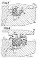
- Figs. 3 and 4 schematically illustrate a mold in which seals can be made by the inventive steps.
- Figs. 2 and 3 show a mold assembly 100, including an upper insert portion 102, a lower or core portion 104, and an outer ring portion 106. When completely closed (Fig. 3), the parts of the mold assembly 100 form a cavity in which the seal is molded by surrounding the casing 12 with an elastomer 20.
- a lower mold core 104 includes an annular end face forming surface 108 having circumferentially spaced apart bosses 110 that will form the notches 68 in the outer end face cover 66 of the seal.
- the lower mold core 104 also includes an angled, inclined surface 112, part of which will form one surface of the flex section 46.
- a surface 114 forms the air side 34 of the seal, and another frustoconical surface 116 forms a part of the oil side 32 of the lip body 30. These surfaces meet at a sharp seal band-forming notch 118.
- the ring portion 106 of the mold 100 includes a radially outermost contoured surface portion 120 which will form an exterior seal mounting surface 24.
- the top insert 102 includes an annular surface 122 adapted to form the axially inner end face surface 28 of the seal and a large land 124, the radially inner portion 126 of which forms the radially outer spring cover surface 39 in the finished seal.
- Figs. 2 and 4 show a spring positioner 128 made up of plural spaced apart, generally L-shaped fingers 130, each of which includes a radial leg 132 and an axial leg 134 for contacting and supporting the facing portions of the garter spring 38.
- Each leg 132, 134 of the finger 130 is about equal in length to the diameter of the coil in the spring 38.
- legs 132, 134 of each finger 130 were about 0.230 to about 0.250 inches in length, with the fingers being about 0.10 inches wide (circumferential) and the ribs being about an equal width. Thus, for every circumferential inch of seal size, there might be approximately five pockets and five ribs.
- annular, entirely flat surface 136 is present. Where the fingers 130 forming the radial portions of the lip body 30 are present, there will be notches 46 in the finished seal, and where the fingers 130 are absent, there will be ribs 48 in the finished product. In a large diameter seal, (23 inches O.D.), there will be several hundred ribs and pockets approximately 0.100 inches wide.
- a garter spring 38 is assembled from coil spring stock cut to the proper length and joined so as to form an endless hoop spring that is positioned over the fingers 130 in the mold 100, held there by its own resiliency.
- the mold halves 102, 104 are then closed with the spring 38 so positioned and the fluent rubber is forced into the molding cavity defined by the mold surfaces just described.
- the finished seal thus contains a rubber outside diameter and a spring which is covered entirely or almost entirely by rubber.
- the contour of the spring may be seen through the thin residual web of material.
- Ribs 48 cover other parts of the spring.
- an experimental seal like that of Fig. 10 was made with no embedded garter spring. In the seal tooling, the lip-forming surfaces of the cavity had an inside diameter of 3.000 inches. In the free state, a seal made in this mold and having no spring shrunk 0.071", to 2.929" (I.D.). Subsequently, an otherwise identical seal was made using a mold such as that shown in Figs. 2 and 11.
- a garter spring 38 was formed into a continuous loop, its assembled inside diameter ("A.I.D.") was measured and the spring was positioned and retained under spring tension on the axial legs 134 of the fingers 130. Additional seals were made using garter springs 38 of assembled inside diameters differing by each other by 0.020". All springs exerted some tension or preload on the mold fingers.
- Tests showed that considerable variations in radial load could be attained.
- Test shafts were made with an I.D. of 3.00 inches. Additional test shafts were also made, each larger than the other by 0.020 inches.
- Some seals developed a radial load of less than 1 ounce per inch of shaft circumference while others displayed values in excess of 32 ounces per inch of shaft circumference.
- the variation in as-molded inner diameters with and without springs aggregated almost 0.070 inches in a 3 inch diameter seal.
- seals of the same size are called upon to provide different radial loads, the degree of preload may be varied.
- An embedded spring provides both resistance to outward deformation and resistance to rubber shrinkage.
- a single mold can utilize springs of different assembled inner diameters to control the out-of-the-mold shrinkage.
- An identical mold using springs of three different assembled inner diameters (A.I.D.) varied the size of the seal I.D. as it came from the mold, creating initial size differences and different molded interferences with an associated shaft. Using the invention, the behavior of the seal can be determined in advance.
- Some mold spring positioners comprised individual fingers 130, formed into a ring.
- Fig. 12 shows that individual pins 130b may be used as fingers, with each pin including a cylindrical shank 131b and a flattened portion 133b facing radially outward for engagement with a garter spring 38b.
- the mold insert 102b includes an opening 135b for the shank 131b.
- the flattened surface 133b and the radial surface 137b form counterparts 134B, 136b to the legs of the positioner in the other embodiments.
- a reverse draft or slant may be used on certain finger surfaces (Fig. 10).
- the innermost tip 135 of the leg 134a is of slightly larger diameter than the surface 151a. This will retain the spring in place during seal formation but the amount of reverse draft or undercut will not impede removing the fingers from the seal when it is taken from the mold.
- the entire spring-engaging surface of the finger 130 in Fig. 8 may be slightly inclined rather than being constructed as shown.
- Fig. 8 shows a preferred method of making the fingers 130.
- the mold is initially constructed with a continuous ridge or land extending into the molding cavity. After the land is formed, a plurality of radial cuts are made flush with an end face surface of the mold, converting a single continuous land into a plurality of individual fingers.
- steps are not necessary, as this involves simply placing a series of holes in a mold end face and pressing the shanks of the pins that support the spring into the openings that are arranged in a circular locus.
Landscapes
- Engineering & Computer Science (AREA)
- General Engineering & Computer Science (AREA)
- Mechanical Engineering (AREA)
- Manufacturing & Machinery (AREA)
- Sealing With Elastic Sealing Lips (AREA)
- Gasket Seals (AREA)
- Sealing Devices (AREA)
- Diaphragms And Bellows (AREA)
Claims (11)
- Fluiddichtungsbaugruppe, die kombiniert umfasst: eine Gehäuseeinheit (12) mit axialen und radialen Flanschen (14; 16) und einen elastomeren Lippenkörperteil (30) mit kegelstumpfartigen, axial nach außen gerichteten Luft- und axial nach innen gerichteten Ölseitenflächen (34; 32), die an einem Innendurchmesserteil zusammentreffen, um so ein Fluiddichtungsband (36) zu bilden, das in Gebrauch eine zugehörige Welle berührt, eine durchgehende, sich am Umfang erstreckende Ringbandfeder (38) eingebettet in dem genannten Lippenkörper (30), eine axial innere Oberfläche des genannten Lippenkörpers (30) teilweise begrenzt durch mehrere voneinander beabstandete Rippen (48), wobei der Rest durch Taschen (46) mit dicht angrenzend an die radial und axial innersten Teile der genannten Ringbandfeder (38) liegenden Teilen begrenzt wird, wobei der genannte Lippenkörperteil (30) mit einem radial inneren Teil (59) des genannten radialen Gehäuseflanschs (16) durch einen flexiblen Halsabschnitt (64) mit dünnem radialen Querschnitt verbunden ist, wobei die genannte Ringbandfeder (38) im freien Zustand der genannten Dichtung eine radial nach innen gerichtete Vorspannungskraft ausübt, um so radialer Ausdehnung der genannten Dichtung zu widerstehen, und das den genannten Lippenkörper (30) aufweisende elastomere Material radial nach innen auf die genannte Feder (38) einwirkt, um die genannte Feder (38) unter eine radiale zusammendrückende Spannung zu setzen, wobei die genannte Feder (38) auch Abmessungsschrumpfen des genannten Dichtungsbands widersteht.
- Fluiddichtungsbaugruppe nach Anspruch 1, bei der der genannte axiale Gehäuseflansch (14) durch eine zylindrische Gummiausbildung bedeckt ist, die eine radial nach außen gerichtete zylindrische Anbringungsfläche bereitstellt.
- Fluiddichtungsbaugruppe nach Anspruch 1 oder 2, bei der die genannten Taschen (46) eine allgemein L-förmige Konfiguration haben.
- Fluiddichtungsbaugruppe nach einem der vorhergehenden Ansprüche, bei der das genannte gesamte Gehäuse im wesentlichen vollständig durch das den genannten Lippenkörperteil (30) aufweisende gleiche elastomere Material umschlossen ist.
- Dichtungsbildungsformbaugruppe, die kombiniert umfasst: wenigstens zwei Dichtungsformteile (102, 104), die zwischen einem offenen und geschlossenen Teil zum Aufnehmen und Positionieren eines Dichtungsgehäuses darin bewegbar sind, wobei jeder der genannten Teile (102, 104) eine Anzahl ringförmiger Oberflächen aufweist und alle der genannten Oberflächen kombiniert werden, um einen Formhohlraum in der geschlossenen Position der genannten Form zu bilden, wobei die genannten Oberflächen diejenigen einschließen, die zum Bilden eines Dichtungslippenkörpers ausgelegt sind, welcher eine radial äußerste Lippenkörperoberfläche, teilweise radial nach innen gerichtete kegelstumpfartige axial nach außen gerichtete Luft- und axial nach innen gerichtete Ölseiteflächen, die zum Bilden eines Dichtungsbandes zusammentreffen, und einen flexiblen Halsabschnitt umfasst, der den genannten Lippenkörper mit dem genannten Gehäuse verbindet, wobei einer der genannten Formteile weiter eine Ringbandfeder-Positioniereinrichtung umfasst und die genannte Ringbandfeder-Positioniereinrichtung (128) eine Anzahl am Umfang dicht voneinander beabstandeter Finger (130) aufweist, die sich in dem den genannten Lippenkörper bildenden Teil in dem genannten Formhohlraum allgemein axial desselben erstrecken und eine Ringbandfeder innerhalb des genannten Hohlraums positionieren, wobei die genannten Finger (130) radial nach außen gerichtete Oberflächen zum Verhindern von radial nach innen gerichteter Bewegung der genannten Ringbandfeder aufweisen und sich wenigstens teilweise radial erstreckende Oberflächen für axiale Positionierung der genannten Ringbandfeder umfassen, wodurch, wenn die genannten Formhälften geschlossen sind, die genannte Ringbandfeder innerhalb des genannten Lippenkörpers positioniert ist und von den radial äußeren und axial inneren Oberflächen desselben beabstandet ist, wobei sich die genannten Finger (130) beim Öffnen der genannten Form aus dem genannten Hohlraum zurückziehen und eine Anzahl benachbart angeordneter, axial offener Taschen in dem Teil des Dichtungslippenkörpers bilden, der radial nach außen von dem genannten Dichtungsbandbereich liegt.
- Dichtungsbildungsformbaugruppe nach Anspruch 5, bei der die den genannten Formhohlraum begrenzenden genannten Oberflächen Oberflächen einschließen, die eine Außendurchmesser-Anbringungsfläche an der genannten Dichtung bilden.
- Dichtungsbildungsformbaugruppe nach Anspruch 5 oder 6, bei der die den genannten Hohlraum begrenzenden genannten Oberflächen Oberflächen einschließen, die das genannte Dichtungsgehäuse vollständig umschließen, wodurch alle Oberflächen desselben in dem zum Bilden des genannten Dichtungsendprodukts verwendeten Elastomer eingekapselt werden.
- Formbaugruppe nach einem der Ansprüche 5 bis 7, bei der die genannte Ringbandfeder-Positioniereinrichtung (128) eine große Anzahl dicht am Umfang beabstandeter, allgemein L-förmiger Finger umfasst, wobei jeder der genannten Finger eine axiale Federhaltefläche und eine sich radial erstreckende Federpositionierfläche aufweist.
- Formbaugruppe nach Anspruch 8, bei der die genannten Finger sich allgemein axial erstreckende federergreifende Oberflächen mit einer leicht umgekehrten Verstreckung dazu zum richtigen Lokalisieren der genannten Ringbandfeder einschließen.
- Dichtungsbildungsform nach einem der Ansprüche 5 bis 9, bei der die genannte Ringbandfeder-Positioniereinrichtung (128) eine Anzahl sich allgemein axial erstreckender Federpositionierstifte aufweist, wobei jeder der genannten Stifte sich axial und radial erstreckende Oberflächenteile umfasst, die zum Ergreifen eines Teils der genannten Ringbandfeder ausgelegt sind.
- Verfahren zum Bilden einer Fluiddichtung, wobei das genannte Verfahren die Schritte umfasst, relativ bewegbare Formteile mit Oberflächen zu bilden, die in ihrer geschlossenen Position den Umriss einer Öldichtung begrenzen, welche einen Dichtungslippenkörper mit kegelstumpfartigen axial nach außen gerichteten Luft- und axial nach innen gerichteten Ölseitenflächen, die entlang eines kreisförmigen Orts zusammentreffen, um ein Dichtungsband mit beabsichtigtem Kontakt mit einer zugehörigen Welle zu bilden, und zusätzliche Oberflächen umfasst, die einen radial äußersten ringförmigen Lippenkörperteil und einen flexiblen Halsteil begrenzen, der den genannten Lippenkörper mit dem Rest der genannten Dichtung verbindet, wobei das genannte Verfahren umfasst, eine am Umfang durchgehende Ringbandfeder vorzuspannen und anschließend über den radial nach außen gerichteten Oberflächen einer Anzahl am Umfang angeordneter, innerhalb des genannten Hohlraums liegender Finger und unter Aufrechterhaltung der Spannung auf der genannten Ringbandfeder zu positionieren, so dass die genannte Feder eine radial nach innen gerichtete Kraft auf die genannten Finger ausübt, die genannte Form mit einem flüssigen, aushärtbaren Elastomer zu füllen, während die genannte Feder an den genannten Fingern positioniert gehalten wird, das genannte Elastomer aushärten zu lassen und anschließend die genannten Finger von dem genannten Hohlraum zu entfernen, um mehrere voneinander beabstandete Taschen in einer axial inneren Oberfläche des genannten Dichtungslippenkörpers zu bilden, wobei die genannte Feder innerhalb des genannten Lippenkörpers positioniert ist und eine radial nach innen gerichtete Kraft ausübt, die darauf gerichtet ist, Vergrößerung des Durchmessers des genannten Dichtungsbands zu widerstehen.
Applications Claiming Priority (2)
| Application Number | Priority Date | Filing Date | Title |
|---|---|---|---|
| US613159 | 1984-05-23 | ||
| US08/613,159 US5730444A (en) | 1996-03-08 | 1996-03-08 | Seal with embedded garter spring |
Publications (2)
| Publication Number | Publication Date |
|---|---|
| EP0795702A1 EP0795702A1 (de) | 1997-09-17 |
| EP0795702B1 true EP0795702B1 (de) | 2002-05-22 |
Family
ID=24456116
Family Applications (1)
| Application Number | Title | Priority Date | Filing Date |
|---|---|---|---|
| EP97301539A Expired - Lifetime EP0795702B1 (de) | 1996-03-08 | 1997-03-07 | Dichtung mit eingebetteter Ringfeder |
Country Status (8)
| Country | Link |
|---|---|
| US (2) | US5730444A (de) |
| EP (1) | EP0795702B1 (de) |
| JP (1) | JPH1047493A (de) |
| AT (1) | ATE217944T1 (de) |
| AU (1) | AU722295B2 (de) |
| CA (1) | CA2199320C (de) |
| DE (1) | DE69712664T2 (de) |
| ES (1) | ES2176618T3 (de) |
Families Citing this family (39)
| Publication number | Priority date | Publication date | Assignee | Title |
|---|---|---|---|---|
| FR2790802B1 (fr) | 1999-03-10 | 2001-04-20 | Roulements Soc Nouvelle | Ensemble preassemble formant joint a etancheite magnetique et roulement ou palier incorporant un tel ensemble |
| US6398539B1 (en) * | 2000-08-15 | 2002-06-04 | Lawrence Equipment, Inc. | Pizza die with seal |
| US6651988B2 (en) | 2000-12-27 | 2003-11-25 | General Dynamics Advanced Information Systems, Inc. | Compact actuator with hydraulic seal |
| US7025357B2 (en) * | 2001-06-08 | 2006-04-11 | Freudenberg-Nok General Partnership | Shaft seal having lip supports |
| JP2003035373A (ja) * | 2001-07-23 | 2003-02-07 | Toyota Industries Corp | 軸封装置及び該軸封装置を備えた圧縮機、軸封方法 |
| JP2003343737A (ja) * | 2002-05-30 | 2003-12-03 | Mitsubishi Cable Ind Ltd | 回転軸シール |
| US6682079B2 (en) | 2002-05-31 | 2004-01-27 | Federal-Mogul World Wide, Inc. | Metal plate gasket |
| JP2004232689A (ja) * | 2003-01-29 | 2004-08-19 | Nok Corp | 密封装置 |
| US7004477B2 (en) * | 2003-05-21 | 2006-02-28 | Freudenberg-Nok General Partnership | Reduced load gasket |
| US8002287B2 (en) * | 2004-02-09 | 2011-08-23 | Freudenberg-Nok General Partnership | Hand assemblable fuel injector seal |
| US7798497B2 (en) * | 2007-03-19 | 2010-09-21 | Freudenberg-Nok General Partnership | Tight package sensor seal |
| US20050173869A1 (en) * | 2004-02-09 | 2005-08-11 | Freudenberg-Nok General Partnership | Spark plug tube seal |
| US20060163818A1 (en) * | 2005-01-24 | 2006-07-27 | Breen Bryan S | Shaft seal with memory metal retainer spring |
| US7331359B2 (en) * | 2005-04-19 | 2008-02-19 | Kohler Co. | Valve with bi-loading seal |
| ITMO20050130A1 (it) * | 2005-05-26 | 2006-11-27 | Tenute S R L | Guarnizione di tenuta e relativo metodo di realizzazione. |
| US7681295B2 (en) * | 2006-06-29 | 2010-03-23 | Skf Usa Inc. | Method of making improved large diameter seals |
| US20090108536A1 (en) * | 2007-10-31 | 2009-04-30 | Freudenberg-Nok General Partnership | Actuator Seal |
| JP6129640B2 (ja) * | 2013-05-15 | 2017-05-17 | 株式会社ミツトヨ | 防塵部材及び測定器 |
| JP6125898B2 (ja) * | 2013-05-15 | 2017-05-10 | 株式会社ミツトヨ | リニアエンコーダ |
| US9963395B2 (en) | 2013-12-11 | 2018-05-08 | Baker Hughes, A Ge Company, Llc | Methods of making carbon composites |
| US9325012B1 (en) | 2014-09-17 | 2016-04-26 | Baker Hughes Incorporated | Carbon composites |
| US10315922B2 (en) | 2014-09-29 | 2019-06-11 | Baker Hughes, A Ge Company, Llc | Carbon composites and methods of manufacture |
| US10480288B2 (en) | 2014-10-15 | 2019-11-19 | Baker Hughes, A Ge Company, Llc | Articles containing carbon composites and methods of manufacture |
| US9962903B2 (en) | 2014-11-13 | 2018-05-08 | Baker Hughes, A Ge Company, Llc | Reinforced composites, methods of manufacture, and articles therefrom |
| US9745451B2 (en) | 2014-11-17 | 2017-08-29 | Baker Hughes Incorporated | Swellable compositions, articles formed therefrom, and methods of manufacture thereof |
| US11097511B2 (en) | 2014-11-18 | 2021-08-24 | Baker Hughes, A Ge Company, Llc | Methods of forming polymer coatings on metallic substrates |
| US10300627B2 (en) | 2014-11-25 | 2019-05-28 | Baker Hughes, A Ge Company, Llc | Method of forming a flexible carbon composite self-lubricating seal |
| US9726300B2 (en) * | 2014-11-25 | 2017-08-08 | Baker Hughes Incorporated | Self-lubricating flexible carbon composite seal |
| US9714709B2 (en) | 2014-11-25 | 2017-07-25 | Baker Hughes Incorporated | Functionally graded articles and methods of manufacture |
| US9840887B2 (en) | 2015-05-13 | 2017-12-12 | Baker Hughes Incorporated | Wear-resistant and self-lubricant bore receptacle packoff tool |
| US10247311B2 (en) | 2015-06-03 | 2019-04-02 | Parker-Hannifin Corporation | Variable height backup assembly for articulating boots |
| CN105546119A (zh) * | 2016-02-02 | 2016-05-04 | 天紫环保投资控股有限公司 | 用于蒸汽弹射装置的高温高压的滑动密封结构 |
| US10125274B2 (en) | 2016-05-03 | 2018-11-13 | Baker Hughes, A Ge Company, Llc | Coatings containing carbon composite fillers and methods of manufacture |
| US10344559B2 (en) | 2016-05-26 | 2019-07-09 | Baker Hughes, A Ge Company, Llc | High temperature high pressure seal for downhole chemical injection applications |
| US11280042B2 (en) * | 2017-05-03 | 2022-03-22 | Nypro Inc. | Apparatus, system, and method of providing a liquid level monitor |
| US12442478B2 (en) | 2019-12-17 | 2025-10-14 | Team Industrial Services, Inc. | Pipe isolation device with seal |
| CN112936884B (zh) * | 2021-01-29 | 2022-08-23 | 重庆嘉涌电子有限公司 | Vr眼镜框加工用压合工装 |
| DE102022117919B4 (de) | 2022-07-18 | 2024-02-29 | Trelleborg Sealing Solutions Germany Gmbh | Radialwellendichtring, Radialwellendichtung und Radialwellendichtungsanordnung |
| US12571281B1 (en) | 2024-12-30 | 2026-03-10 | Halluburton Energy Services, Inc. | Garter spring assembly for sealing devices in well systems |
Family Cites Families (25)
| Publication number | Priority date | Publication date | Assignee | Title |
|---|---|---|---|---|
| US2249141A (en) * | 1936-04-14 | 1941-07-15 | Nat Oil Seal Co | Fluid seal |
| US2294589A (en) * | 1939-02-13 | 1942-09-01 | Carl C Waterbury | Method for making rubber articles |
| US2361348A (en) * | 1939-10-12 | 1944-10-24 | Spalding A G & Bros Inc | Process and apparatus for making balls |
| US2321340A (en) * | 1941-04-09 | 1943-06-08 | Carl C Waterbury | Rubber article and method of making same |
| US2581817A (en) * | 1946-07-02 | 1952-01-08 | Simmer Otto | Packing ring |
| US2949635A (en) * | 1957-02-26 | 1960-08-23 | Chicago Rawhide Mfg Co | Seal molding apparatus |
| US3095611A (en) * | 1960-01-12 | 1963-07-02 | John E Borah | Mold |
| US3162456A (en) * | 1961-03-03 | 1964-12-22 | Rex Chainbelt Inc | Seal with reinforced mounting |
| FR1358235A (fr) * | 1963-06-04 | 1964-04-10 | Federal Mogul Bower Bearings | Joint d'étanchéité pour arbres |
| US3246369A (en) * | 1964-03-09 | 1966-04-19 | Federal Mogul Corp | Mold for fluid seal |
| DE1223641B (de) * | 1964-04-08 | 1966-08-25 | Goetzewerke | Wellendichtring |
| US3405214A (en) * | 1965-04-08 | 1968-10-08 | Tri State Products Inc | Molding apparatus and process |
| US3561770A (en) * | 1968-10-07 | 1971-02-09 | Federal Mogul Corp | Shaft seal |
| US3733155A (en) * | 1970-01-06 | 1973-05-15 | Federal Mogul Corp | Apparatus for making an elastomeric annular seal with enclosed garter spring |
| US3666852A (en) * | 1970-01-06 | 1972-05-30 | Federal Mogul Corp | Method for making an elastomeric annular seal with enclosed garter spring |
| US3656227A (en) * | 1970-03-26 | 1972-04-18 | Gen Motors Corp | Method of making a mold for bidirectional hydrodynamic shaft seals |
| US3851037A (en) * | 1971-05-03 | 1974-11-26 | Federal Mogul Corp | Method for molding dual-lip shaft seals with a garter spring molded into the auxiliary lip |
| DE2628703C3 (de) * | 1976-06-25 | 1980-10-09 | Maschinen- Und Werkzeugbau Gmbh, 3563 Dautphetal | Anordnung und Verfahren zur Herstellung von Profilen, insbesondere für Fenster und Türen |
| DE2902531C2 (de) * | 1979-01-24 | 1984-05-10 | Kaco Gmbh + Co, 7100 Heilbronn | Radial-Wellendichtring |
| JPS56150659A (en) * | 1980-04-22 | 1981-11-21 | Akira Washida | Shaft-sealing element |
| SE8105825L (sv) * | 1981-10-02 | 1983-04-03 | Forsheda Gummifabrik Ab | Anordning vid form for framstelling av med forsterkningselement forsedda foremal av elastmaterial |
| JPS58187656A (ja) * | 1982-04-28 | 1983-11-01 | Honda Motor Co Ltd | オイルシ−ル |
| US5182032A (en) * | 1990-07-09 | 1993-01-26 | Paige Manufacturing Company Incorporated | Apparatus for plastic injection overmolding |
| US5213749A (en) * | 1991-07-31 | 1993-05-25 | Westinghouse Air Brake Company | Method of forming a rubber seal having a metallic insert |
| US5348314A (en) * | 1993-03-12 | 1994-09-20 | Dana Corporation | Seals with indicia and method of molding seals with indicia to allow inspection after trimming |
-
1996
- 1996-03-08 US US08/613,159 patent/US5730444A/en not_active Expired - Lifetime
-
1997
- 1997-03-06 AU AU15132/97A patent/AU722295B2/en not_active Ceased
- 1997-03-06 CA CA002199320A patent/CA2199320C/en not_active Expired - Lifetime
- 1997-03-07 AT AT97301539T patent/ATE217944T1/de active
- 1997-03-07 EP EP97301539A patent/EP0795702B1/de not_active Expired - Lifetime
- 1997-03-07 JP JP9070446A patent/JPH1047493A/ja not_active Withdrawn
- 1997-03-07 ES ES97301539T patent/ES2176618T3/es not_active Expired - Lifetime
- 1997-03-07 DE DE69712664T patent/DE69712664T2/de not_active Expired - Lifetime
- 1997-09-05 US US08/924,332 patent/US5928676A/en not_active Expired - Lifetime
Also Published As
| Publication number | Publication date |
|---|---|
| ATE217944T1 (de) | 2002-06-15 |
| ES2176618T3 (es) | 2002-12-01 |
| CA2199320C (en) | 2005-02-01 |
| US5730444A (en) | 1998-03-24 |
| JPH1047493A (ja) | 1998-02-20 |
| AU1513297A (en) | 1997-09-11 |
| CA2199320A1 (en) | 1997-09-08 |
| AU722295B2 (en) | 2000-07-27 |
| EP0795702A1 (de) | 1997-09-17 |
| DE69712664D1 (de) | 2002-06-27 |
| DE69712664T2 (de) | 2002-10-24 |
| US5928676A (en) | 1999-07-27 |
| MX9701747A (es) | 1998-03-31 |
Similar Documents
| Publication | Publication Date | Title |
|---|---|---|
| EP0795702A1 (de) | Dichtung mit eingebetteter Ringfeder | |
| US5759466A (en) | Method of making lip-type oil seals having improved sealing edge | |
| US4254960A (en) | Sealing device | |
| EP1924792B1 (de) | Radiale dichtung und herstellungsverfahren dafür | |
| US5853178A (en) | Bellowed seal | |
| FI83486B (fi) | Foerfarande foer framstaellning av ett speciellt i roerskarvar anvaendbart taetningsstycke och form foer framstaellning av taetningsstycket. | |
| US5884786A (en) | Preform and closure for blow molded articles | |
| US4580962A (en) | Seal mold and method | |
| US5492669A (en) | Tire mold and method of molding the tire | |
| US5911936A (en) | Process for producing radiator support | |
| GB2198387A (en) | Improved seal, seal mould and method | |
| EP0230120B1 (de) | Herstellung einer Kompaktdichtung | |
| KR960701330A (ko) | 밀봉 장치, 몰딩 공구 및 파이프(a sealing device, a mould element and a pipe) | |
| US20200400233A1 (en) | Dust proof sleeve | |
| US1854708A (en) | Packing and method of forming the same | |
| US3993420A (en) | Retainer assembly for mold plate | |
| US6623684B1 (en) | Method for molding a gasket for hard disc drive unit | |
| US5050298A (en) | Method of manufacturing a mechanically-bonded, monolithic sealing ring for stuffing box including axially central portion made of compressed flexible foamed graphite tape | |
| US5135240A (en) | Mechanically-bonded, monolithic sealing ring for stuffing box including axially central portion made of compressed flexible foamed graphite tape | |
| MXPA97001747A (en) | Improved seal with toroidal incrust spring | |
| JP2791857B2 (ja) | ベローズ製造用金型装置 | |
| JP2668135B2 (ja) | シール製造方法 | |
| US4589665A (en) | Fluorocarbon resin seal and method of making same | |
| JP3065376B2 (ja) | 型成形品およびその成形方法並びに成形型 | |
| US1657014A (en) | Method of making cushion-tire structures |
Legal Events
| Date | Code | Title | Description |
|---|---|---|---|
| PUAI | Public reference made under article 153(3) epc to a published international application that has entered the european phase |
Free format text: ORIGINAL CODE: 0009012 |
|
| AK | Designated contracting states |
Kind code of ref document: A1 Designated state(s): AT BE CH DE DK ES FI FR GB GR IE IT LI LU MC NL PT SE |
|
| 17P | Request for examination filed |
Effective date: 19980302 |
|
| GRAG | Despatch of communication of intention to grant |
Free format text: ORIGINAL CODE: EPIDOS AGRA |
|
| 17Q | First examination report despatched |
Effective date: 20010410 |
|
| GRAG | Despatch of communication of intention to grant |
Free format text: ORIGINAL CODE: EPIDOS AGRA |
|
| GRAG | Despatch of communication of intention to grant |
Free format text: ORIGINAL CODE: EPIDOS AGRA |
|
| GRAH | Despatch of communication of intention to grant a patent |
Free format text: ORIGINAL CODE: EPIDOS IGRA |
|
| GRAH | Despatch of communication of intention to grant a patent |
Free format text: ORIGINAL CODE: EPIDOS IGRA |
|
| GRAA | (expected) grant |
Free format text: ORIGINAL CODE: 0009210 |
|
| PG25 | Lapsed in a contracting state [announced via postgrant information from national office to epo] |
Ref country code: LI Free format text: LAPSE BECAUSE OF FAILURE TO SUBMIT A TRANSLATION OF THE DESCRIPTION OR TO PAY THE FEE WITHIN THE PRESCRIBED TIME-LIMIT Effective date: 20020522 Ref country code: GR Free format text: LAPSE BECAUSE OF FAILURE TO SUBMIT A TRANSLATION OF THE DESCRIPTION OR TO PAY THE FEE WITHIN THE PRESCRIBED TIME-LIMIT Effective date: 20020522 Ref country code: CH Free format text: LAPSE BECAUSE OF FAILURE TO SUBMIT A TRANSLATION OF THE DESCRIPTION OR TO PAY THE FEE WITHIN THE PRESCRIBED TIME-LIMIT Effective date: 20020522 |
|
| REF | Corresponds to: |
Ref document number: 217944 Country of ref document: AT Date of ref document: 20020615 Kind code of ref document: T |
|
| REG | Reference to a national code |
Ref country code: GB Ref legal event code: FG4D |
|
| REG | Reference to a national code |
Ref country code: CH Ref legal event code: EP |
|
| REG | Reference to a national code |
Ref country code: IE Ref legal event code: FG4D |
|
| REF | Corresponds to: |
Ref document number: 69712664 Country of ref document: DE Date of ref document: 20020627 |
|
| PG25 | Lapsed in a contracting state [announced via postgrant information from national office to epo] |
Ref country code: PT Free format text: LAPSE BECAUSE OF FAILURE TO SUBMIT A TRANSLATION OF THE DESCRIPTION OR TO PAY THE FEE WITHIN THE PRESCRIBED TIME-LIMIT Effective date: 20020822 Ref country code: DK Free format text: LAPSE BECAUSE OF FAILURE TO SUBMIT A TRANSLATION OF THE DESCRIPTION OR TO PAY THE FEE WITHIN THE PRESCRIBED TIME-LIMIT Effective date: 20020822 |
|
| ET | Fr: translation filed | ||
| REG | Reference to a national code |
Ref country code: CH Ref legal event code: PL |
|
| REG | Reference to a national code |
Ref country code: ES Ref legal event code: FG2A Ref document number: 2176618 Country of ref document: ES Kind code of ref document: T3 |
|
| PGFP | Annual fee paid to national office [announced via postgrant information from national office to epo] |
Ref country code: IE Payment date: 20030224 Year of fee payment: 7 |
|
| PGFP | Annual fee paid to national office [announced via postgrant information from national office to epo] |
Ref country code: MC Payment date: 20030225 Year of fee payment: 7 |
|
| PGFP | Annual fee paid to national office [announced via postgrant information from national office to epo] |
Ref country code: LU Payment date: 20030310 Year of fee payment: 7 |
|
| PLBE | No opposition filed within time limit |
Free format text: ORIGINAL CODE: 0009261 |
|
| STAA | Information on the status of an ep patent application or granted ep patent |
Free format text: STATUS: NO OPPOSITION FILED WITHIN TIME LIMIT |
|
| 26N | No opposition filed |
Effective date: 20030225 |
|
| PG25 | Lapsed in a contracting state [announced via postgrant information from national office to epo] |
Ref country code: LU Free format text: LAPSE BECAUSE OF NON-PAYMENT OF DUE FEES Effective date: 20040307 |
|
| PG25 | Lapsed in a contracting state [announced via postgrant information from national office to epo] |
Ref country code: IE Free format text: LAPSE BECAUSE OF NON-PAYMENT OF DUE FEES Effective date: 20040308 |
|
| PG25 | Lapsed in a contracting state [announced via postgrant information from national office to epo] |
Ref country code: MC Free format text: LAPSE BECAUSE OF NON-PAYMENT OF DUE FEES Effective date: 20040331 |
|
| REG | Reference to a national code |
Ref country code: IE Ref legal event code: MM4A |
|
| PGFP | Annual fee paid to national office [announced via postgrant information from national office to epo] |
Ref country code: ES Payment date: 20090325 Year of fee payment: 13 |
|
| PGFP | Annual fee paid to national office [announced via postgrant information from national office to epo] |
Ref country code: NL Payment date: 20090310 Year of fee payment: 13 Ref country code: FI Payment date: 20090216 Year of fee payment: 13 |
|
| PGFP | Annual fee paid to national office [announced via postgrant information from national office to epo] |
Ref country code: SE Payment date: 20090306 Year of fee payment: 13 |
|
| PGFP | Annual fee paid to national office [announced via postgrant information from national office to epo] |
Ref country code: FR Payment date: 20090306 Year of fee payment: 13 |
|
| REG | Reference to a national code |
Ref country code: NL Ref legal event code: V1 Effective date: 20101001 |
|
| EUG | Se: european patent has lapsed | ||
| PG25 | Lapsed in a contracting state [announced via postgrant information from national office to epo] |
Ref country code: FI Free format text: LAPSE BECAUSE OF NON-PAYMENT OF DUE FEES Effective date: 20100307 |
|
| REG | Reference to a national code |
Ref country code: FR Ref legal event code: ST Effective date: 20101130 |
|
| PG25 | Lapsed in a contracting state [announced via postgrant information from national office to epo] |
Ref country code: NL Free format text: LAPSE BECAUSE OF NON-PAYMENT OF DUE FEES Effective date: 20101001 Ref country code: FR Free format text: LAPSE BECAUSE OF NON-PAYMENT OF DUE FEES Effective date: 20100331 |
|
| REG | Reference to a national code |
Ref country code: ES Ref legal event code: FD2A Effective date: 20110419 |
|
| PGFP | Annual fee paid to national office [announced via postgrant information from national office to epo] |
Ref country code: AT Payment date: 20110221 Year of fee payment: 15 |
|
| PG25 | Lapsed in a contracting state [announced via postgrant information from national office to epo] |
Ref country code: ES Free format text: LAPSE BECAUSE OF NON-PAYMENT OF DUE FEES Effective date: 20110404 |
|
| PGFP | Annual fee paid to national office [announced via postgrant information from national office to epo] |
Ref country code: BE Payment date: 20110414 Year of fee payment: 15 |
|
| PG25 | Lapsed in a contracting state [announced via postgrant information from national office to epo] |
Ref country code: ES Free format text: LAPSE BECAUSE OF NON-PAYMENT OF DUE FEES Effective date: 20100308 |
|
| PGFP | Annual fee paid to national office [announced via postgrant information from national office to epo] |
Ref country code: IT Payment date: 20120323 Year of fee payment: 16 |
|
| PG25 | Lapsed in a contracting state [announced via postgrant information from national office to epo] |
Ref country code: SE Free format text: LAPSE BECAUSE OF NON-PAYMENT OF DUE FEES Effective date: 20100308 |
|
| BERE | Be: lapsed |
Owner name: *SKF USA INC. Effective date: 20120331 |
|
| REG | Reference to a national code |
Ref country code: AT Ref legal event code: MM01 Ref document number: 217944 Country of ref document: AT Kind code of ref document: T Effective date: 20120307 |
|
| PG25 | Lapsed in a contracting state [announced via postgrant information from national office to epo] |
Ref country code: AT Free format text: LAPSE BECAUSE OF NON-PAYMENT OF DUE FEES Effective date: 20120307 Ref country code: BE Free format text: LAPSE BECAUSE OF NON-PAYMENT OF DUE FEES Effective date: 20120331 |
|
| PGFP | Annual fee paid to national office [announced via postgrant information from national office to epo] |
Ref country code: GB Payment date: 20130225 Year of fee payment: 17 |
|
| PGFP | Annual fee paid to national office [announced via postgrant information from national office to epo] |
Ref country code: DE Payment date: 20130328 Year of fee payment: 17 |
|
| REG | Reference to a national code |
Ref country code: DE Ref legal event code: R119 Ref document number: 69712664 Country of ref document: DE |
|
| GBPC | Gb: european patent ceased through non-payment of renewal fee |
Effective date: 20140307 |
|
| REG | Reference to a national code |
Ref country code: DE Ref legal event code: R119 Ref document number: 69712664 Country of ref document: DE Effective date: 20141001 |
|
| PG25 | Lapsed in a contracting state [announced via postgrant information from national office to epo] |
Ref country code: DE Free format text: LAPSE BECAUSE OF NON-PAYMENT OF DUE FEES Effective date: 20141001 Ref country code: GB Free format text: LAPSE BECAUSE OF NON-PAYMENT OF DUE FEES Effective date: 20140307 |
|
| PG25 | Lapsed in a contracting state [announced via postgrant information from national office to epo] |
Ref country code: IT Free format text: LAPSE BECAUSE OF NON-PAYMENT OF DUE FEES Effective date: 20140307 |