EP0795413A1 - Drucker - Google Patents
Drucker Download PDFInfo
- Publication number
- EP0795413A1 EP0795413A1 EP97104290A EP97104290A EP0795413A1 EP 0795413 A1 EP0795413 A1 EP 0795413A1 EP 97104290 A EP97104290 A EP 97104290A EP 97104290 A EP97104290 A EP 97104290A EP 0795413 A1 EP0795413 A1 EP 0795413A1
- Authority
- EP
- European Patent Office
- Prior art keywords
- carriage
- printing medium
- printer apparatus
- sliding
- printing
- Prior art date
- Legal status (The legal status is an assumption and is not a legal conclusion. Google has not performed a legal analysis and makes no representation as to the accuracy of the status listed.)
- Granted
Links
Images


Classifications
-
- B—PERFORMING OPERATIONS; TRANSPORTING
- B41—PRINTING; LINING MACHINES; TYPEWRITERS; STAMPS
- B41J—TYPEWRITERS; SELECTIVE PRINTING MECHANISMS, i.e. MECHANISMS PRINTING OTHERWISE THAN FROM A FORME; CORRECTION OF TYPOGRAPHICAL ERRORS
- B41J25/00—Actions or mechanisms not otherwise provided for
- B41J25/304—Bodily-movable mechanisms for print heads or carriages movable towards or from paper surface
- B41J25/308—Bodily-movable mechanisms for print heads or carriages movable towards or from paper surface with print gap adjustment mechanisms
- B41J25/3082—Bodily-movable mechanisms for print heads or carriages movable towards or from paper surface with print gap adjustment mechanisms with print gap adjustment means on the print head carriage, e.g. for rotation around a guide bar or using a rotatable eccentric bearing
-
- B—PERFORMING OPERATIONS; TRANSPORTING
- B41—PRINTING; LINING MACHINES; TYPEWRITERS; STAMPS
- B41J—TYPEWRITERS; SELECTIVE PRINTING MECHANISMS, i.e. MECHANISMS PRINTING OTHERWISE THAN FROM A FORME; CORRECTION OF TYPOGRAPHICAL ERRORS
- B41J11/00—Devices or arrangements of selective printing mechanisms, e.g. ink-jet printers or thermal printers, for supporting or handling copy material in sheet or web form
- B41J11/0045—Guides for printing material
- B41J11/005—Guides in the printing zone, e.g. guides for preventing contact of conveyed sheets with printhead
Definitions
- the present invention relates to a printer apparatus of a construction wherein a carriage supporting member which extends in the reciprocal movement direction of the carriage supports at least a portion of the carriage, and particularly to a printer apparatus which is capable of achieving stable running of the aforementioned carriage.
- printer apparatuses Recently, in accordance with the development of personal computers and the like, there is more demand for printer apparatuses to be of high speed, high resolution, and low cost.
- the ink-jet method, wire dot method, and thermal transfer method are examples of printer apparatuses which are widely used and are of low cost.
- ink-jet type printers are more excellent than the other methods in terms of silence, high speed, a high degree of fine printing, color capabilities, and so forth, and the demand thereof is growing rapidly.
- This ink-jet printer apparatus does not press the printing medium directly against the printer head, but arranges the printing surface of the printing medium and the printer head so as to be facing another across a certain distance, and ejects ink droplets from the printer head to certain locations on the printing surface of the printing medium.
- a printer apparatus using such a method by means of maintaining the distance between the printer head and the printing medium at a proper distance (hereafter referred to as "head gap"), ink droplets having a constant dot diameter, concentration, and landing properties can be printed to the printing surface of the printing medium.
- Japanese Unexamined Patent Publication No. 3-239844 discloses an arrangement wherein the printing medium is pressed against a transporting roller located upstream from the platen by means of a medium pressing plate, and causing a carriage mounted with the printer head to perform scanning motion in accordance with this medium pressing plate, so that the head gap is automatically corrected in accordance with the change in thickness of the printing medium.
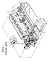
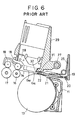
- Fig. 1 shows an example of such a known printer apparatus.
- a platen 1 which is in the form of a plate
- a rotationally driving transporting roller 2 directly underneath a platen 1, which is in the form of a plate, is a rotationally driving transporting roller 2, and the printing medium 5 is pressed against the transporting roller 2 by means of a medium pressing plate 3 which is aided by this transporting roller 2 and a pinch roller 4 which is rotatably attached unto this medium pressing plate 3, thus feeding the printing medium 5 out to the side of the platen 1.
- a carriage 8 mounted with a printer head 7, and is arranged such that the carriage 8 performs scanning motion with the printer head 7 following the guide shaft 6.
- the carriage 8 is in a state of the end thereof being pressed against the medium pressing plate 3 due to its own weight, and thus slides along the medium pressing plate 3.
- the spacing between the medium pressing plate 3 and the transporting roller 2 changes according to change in the thickness of the medium 5, and thus the head gap between the printing surface of the printing medium and the printer head 7 is constantly maintained the same, regardless of the thickness of the printing medium 5.
- An object of the present invention is to provide a printer apparatus wherein stable running of the carriage can be achieved even if there are irregularities in height in the sliding portion of the supporting member which slidably supports the carriage, this member being provided along the direction of motion of the carriage.
- Another object of the present invention is to provide a printer apparatus wherein there is no irregularity in carriage running precision even if there is an offset between the portion where the printing medium exists between the printing medium supporting member and the printing medium pressing member, and where printing medium does not exists between these members.
- a further object of the present invention is to provide a printer apparatus wherein, even in the case where the printing medium pressing member has been constructed so as to be easily flexible in the width direction of the printing medium in order to make the pressure from the printing medium pressing member to the printing medium uniform, the sliding portion of the carriage has been made so as to displace in accordance with the surface form of the printing medium pressing member, so that even of there is existence of fine undulations on the surface of the printing medium pressing member the amplitude thereof is reduced, and the shock of riding up on the offset portion generated on the surface of the printing medium pressing member based on the edge of the printing medium is weakened, thus allowing for the scanning precision of the carriage to be maintained favorably.
- a printer apparatus comprising: a carriage for reciprocally moving a printer head; a carriage supporting member which slidably supports the aforementioned carriage by means of a sliding supporting portion which slidably supports the aforementioned carriage and which guides the movement of the aforementioned carriage; and an displacement portion which is capable of displacement along the surface of the aforementioned sliding portion which a plane vertical to the direction of movement of the aforementioned carriage; thus achieving stable running of the carriage even if there are irregularities in height in the sliding portion of the supporting member which slidably supports the aforementioned carriage, this member being provided along the direction of motion of the carriage.
- a printer apparatus comprising: a printing medium supporting member which supports the printing medium; a printing medium pressing member which is provided across from and opposing this printing medium supporting member so as to be changeable in position and pressed toward the aforementioned printing medium supporting member so as to press the aforementioned printing medium against the printing medium supporting member; a carriage which scans in the width direction of the aforementioned printing medium maintained between the aforementioned printing medium supporting member the aforementioned printing medium pressing member, and which is provided movably in the direction opposing the aforementioned printing medium supporting member and pressed to the side of the aforementioned printing medium pressing member so as to have one end thereof pressed against the surface of the aforementioned printing medium pressing member to the opposite side of the aforementioned printing medium supporting member; and a sliding portion which is provided to the aforementioned one end of this carriage and is in contact slidably with the aforementioned surface of the aforementioned printing medium pressing member, and wherein both ends of the sliding portion are displaceable to said carriage in accordance
- Fig. 3 which schematically illustrates the construction of the principal members of an ink-jet printer apparatus according to the present embodiment
- Fig. 4 which illustrates the overall exterior view
- attached to casing 11 is a shaft 13a of the central portion, a plurality of round plates 14 which are integrally formed with this shaft 13a, and a transporting roller 13 upon the outer circumference of which are provided a plurality of rubber rollers 12, this transporting roller 13 being provided such that both ends are attached so as to be driven rotatably.
- the transporting roller 13 in the present embodiment is arranged so as to the reverse the direction of the printing paper 14 by 180° from the lower side of the casing 11 and transport the printing paper 14 to the upper side of the casing 11, or to transport the printing paper 14 from the rear side of the casing 11 toward the front side of the casing 11 in a generally horizontally maintained state.
- bi-level paper ejecting rollers 16 and 17 downstream from this transporting roller 13 are bi-level paper ejecting rollers 16 and 17, each having a plurality of rubber rollers 15 formed upon the outer circumference thereof, and each rotatably attached to the casing 11 so as to rotate synchronously with the rotation of the transporting roller 13.
- a plate-shaped platen (not shown) which guides the printing paper 14 being fed from the transporting roller 13 to the paper ejecting roller 16 side.
- a paper pressing plate 21 which is retained at a retaining portion 20 formed on the casing 11 by a catching portion 19 formed on the base edge portion, with the leading edge of the paper pressing plate 21 being capable of coming into contact with the topmost edge of the transporting roller 13, this paper pressing plate 21 being capable of displacement up and down with the tip thereof centered on this catching portion 19.
- a plurality of pressing rollers 22 (three in the Figure) for reducing the sliding resistance of the paper pressing plate 21 against the printing paper 14 and thus facilitating smooth transporting of the printing paper 14.
- this paper pressing plate 21 is constructed of a flexible material such as plastic or the like, and is provided with a plurality of cutouts 23 extending from the base edge side toward the leading edge so as to surround each of the pressing rollers 22. Between each of the cutouts 23 are provided a plurality of ribs 24 (two in the Figure) parallel to the cutouts 23, for increasing the rigidity of the portions of the paper pressing plate 21 where the pressing rollers 22 are attached, and torsion coil springs 25 for pressing the leading edge of the paper pressing plate 21 toward the side of the transporting roller 13 are provided in a number corresponding to the number of pressing rollers 22 and are each attached to the upper side of the retaining portion 20 of the casing 11 with one side thereof coming into contact with the paper pressing plate 21 between adjacent ribs 24.
- the shaft 26 of the pressing rollers 22 opposing the transporting roller 13 is constantly maintained parallel thereto, pressing the pressing rollers 22 against the transporting roller 13 with even pressure, thereby changing the rotational position of the paper pressing plate 21 according to the thickness of the printing paper 14.
- a guide shaft 27 with a round cross-sectional form, this being provided parallel with the transporting roller 13, and with both ends being supported by the casing 11. Also, protruding from the carriage 29 which detachably supports a printer head 28 so as to oppose the printing surface of the printing paper 14 on the platen, are a pair of brackets 30 which protrude to the side to the guide shaft 27 and allow the guide shaft 27 to pass slidably through.
- a toothed belt (not shown) is linked to the carriage 29 in a manner generally parallel to the guide shaft 27, and by means of driving this toothed belt by means of a stepping motor (not shown), the printer head 28 is subjected to scanning motion in the width direction of the printing paper 14 along the guide shaft 27.
- the plane opposite to the pressing rollers 22 of the paper pressing plate 21 is an arc plane 31 coaxial with the shaft 26 of the pressing rollers 22, and the bottom edge of the carriage 29 slidably makes contact following this arc plane 31.
- a slanted plane 32 formed to the bottom of this carriage 29 is a slanted plane 32 of an inclination of, e.g., around 30°, so as to be parallel to the shaft 26 of the pressing rollers 22, and also facing the printing surface of the printing paper 14 which opposes the printer head 28.
- the slanted plane 32 which serves as the sliding portion of the present invention is inclined such that a plane extend therefrom intersects the printing surface of the printing paper 14 which is located between the paper ejecting roller 16 and the pressing rollers 22.
- the carriage 29 is rotatably linked to the guide shaft 27, rotation moment occurs due to the weight of the carriage 29 and printer head 28, and the lower edge of the printer head 28 rotates so as to approach the platen.
- the slanted plane 32 of the carriage 29 comes into contact with the arc plane 31 of the paper pressing plate 21, and thus the head gap between the printing surface of the printing paper 14 and the printer head 28 is maintained so as to be practically constant.
- the printing paper 14 is pinched between the transporting roller 13 and pressing rollers 22 of the paper pressing plate 21, via either a horizontal path from behind the casing 11 or a U-turn path from the front bottom side.
- the paper pressing plate 21 is raised by an amount corresponding to the thickness of the printing paper 14, and simultaneously the carriage 29 is also rotated upward so that the head gap between the printing surface of the printing paper 14 and the printer head 28 is maintained so as to be practically constant.
- the carriage 29 scans in the direction of the width of the printing paper 14 and ink is ejected from the printer head 28, thus printing one line.
- the printing paper 14 is pinched between the paper ejecting rollers 16 and 17 by means of spurs 18, so as not to soil the printing surface, and is ejected out from the casing 11.
- the amount of displacement of the slanted plane 32 of the carriage 29 centered around the guide shaft 27 becomes relatively less than the amount of displacement of the pressing rollers 22 of the paper pressing plate 21, thus controlling the ratio of change of the head gap between the printer head 28 and the printing surface of the printing paper 14 regarding the amount of rotation of the paper pressing plate 21.
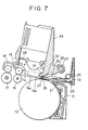
- Fig. 3 an arrangement was prepared wherein the slanted plane 32 of the carriage 29 was inclined by 30° as to the printing surface of the printing paper 14 which is opposing the printer head 28, and adjusted so that the head gap would be 1.39 mm across the entire range of the printer head 28 in the event that the thickness of the printing paper 14 is 0.05 mm in thickness. Then, printing paper 14 of 0.5 mm in thickness was supplied thereto, and as shown in Fig. 7 which illustrates this state, it was found that the maximum head gap G M was 1.54 mm, and the minimum head gap G N was 1.41 mm, well within the permissible margin of error, even if the permissible margin of error is set at, e.g., 19%.
- the head gap is determined at a single value at the assembly stage of the ink-jet printer, but the apparatus may be provided with fine adjustment functions of the head gap.
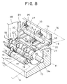
- FIG. 8 The exterior view of the principal components of another embodiment is shown in Fig. 8 and an enlarged cross-sectional structural drawing is illustrated in Fig. 9.
- the members which are of the same function as those of the earlier embodiment are denoted by the same reference numerals, and redundant description thereof will be omitted.
- i.e., rotatably attached to the rear wall portion 33 of the casing 11 which opposes the rear end portion of the paper pressing plate 21 are adjustment plates 34 with a trench-shaped retaining portion 20 formed to the bottom thereof, this rotational attachment being conducted via a pin 35 parallel to the guide shaft 27 passing through the upper portion of the adjustment plates 34.
- the paper pressing plate 21 moves to the right and left directions in Fig. 9 via the catching portion 19, so that the slanted plane 32 of the carriage 29 which comes into contact with the arc plane 31 of the paper pressing plate 21 rotates centrally around the guide shaft 27, so that the head gap between the printing paper 14 and the printer head 28 changes.
- the inclination of the slanted plane 32 of the carriage 29 is set to be 30° as to the printing surface of the printing paper 14 opposing the printer head 28, the head gap can be corrected by 0.3 mm by means of shifting the retaining portion 20 by 1 mm.
- This head gap adjustment can be conducted at any time, even in cases where the head gap has changed due to wearing or the like.
- a slanted plane 32 was formed to the bottom of the carriage 29 and the leading edge portion of the paper pressing plate 21 against which this slanted plane 32 slidably contacts was made to be an arc plane 31, but these may be reversed.
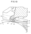
- FIG. 10 A cross-sectional structural drawing of the principal components of yet another embodiment of such an invention is illustrated in Fig. 10.
- the members which are of the same function as those of the earlier embodiments are denoted by the same reference numerals, and redundant description thereof will be omitted.
- the plane opposite to the pressing rollers 22 of the leading edge of the paper pressing plate 21 is parallel with the shaft 26 of the pressing rollers 22, and also forms a slanted plane 36 which is at an inclination of e.g., 30°, as opposed to the printing surface of the printing paper 14 which is opposing the printer head 28, such that the bottom edge of the carriage 29 slidably comes into contact along this slanted plane 36.
- the slanted plane 36 in the present invention is inclined such that a plane extend therefrom intersects the printing surface of the printing paper 14 which is located between the paper ejecting roller 16 and the pressing rollers 22, but there is no problem with the inclination being reversed.
- a convex arc plane 37 protruding to the side of the slanted plane 36 and having an axial line parallel to the shaft 26 of the pressing rollers 22 as the center thereof is formed to the bottom of the carriage 29, so that this convex arc plane 37 serves as the sliding portion in the present invention.
- the paper pressing plate 21 rotates around the catching portion 19 so that the contact position of the arc plane 37 of the of the carriage 29 as opposed to the slanted plane 36 of the paper pressing plate 21 shifts toward the direction of intersection with the shaft 26 of the pressing rollers 22.
- the amount of displacement of the arc plane 37 of the carriage 29 centered around the guide shaft 27 becomes relatively less than the amount of displacement of the pressing rollers 22 of the paper pressing plate 21, thus controlling the ratio of change of the head gap between the printer head 28 and the printing surface of the printing paper 14 regarding the amount of rotation of the paper pressing plate 21.
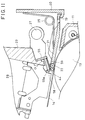
- Fig. 11 is a cross-section view along the plane indicated by the arrows A and B in Fig. 17.
- the sliding guide portion 44 is an arc plane of a constant curvature having an axis generally parallel to the transporting roller 13. Also, the displacement shaft 58 to the sliding plate 59 and the plane of the sliding plate 59 which slides against the sliding guide 44 are generally parallel to the arc plane of the sliding guide 44, and is of a inclined plane so that removal thereof from the guide shaft 27 in the direction of transporting of the printing medium 14 by means of the transporting roller 13 causes approaching thereof.
- Slanting the sliding plate 59 thus has the effect of relieving the phenomena of the extra movement of the printer head. i.e., the greater the inclination is, the less movement there is in correspondence with change in the thickness of the printing medium.
- a 30° inclination such as described regarding the structure of the aforementioned Fig. 3, is preferable.
- brackets 30 protruding therefrom, these brackets protruding toward the guide shaft 27 and having round holes 41 therein whereby the guide shaft 27 can freely pass through, as shown in Fig. 12 illustrating the exterior of the bottom of the carriage 29.
- retaining portions 43 On both sides of the bottom thereof following the scanning direction of the carriage 29 are formed retaining portions 43 in the form of cut-outs, and a pair of folded portions 46 are formed on both ends of the sliding plate 45 which comes into contact with the sliding guide portion 44 formed parallel with the transporting roller 13 in the leading upper plane of the aforementioned paper pressing plate 21, so as to be fitably retained to these retaining portions 43. Also, the fulcrum portion 47 protruding from the lower plane of the carriage 29 comes into contact with the center portion of the sliding plate 45 in the direction of scanning of the carriage 29.
- the sliding plate 45 formed of stainless steel or the like and extending in the scanning direction of the carriage 29 is supported by the retaining portions 43 of the carriage 29 via folded portions 36, and the folded portions 46 alternatively displace upwards and downwards within the retaining portion 43, centered around the fulcrum 47.
- the carriage 29 is linked rotatably to the guide shaft 27, and rotates so as to approach the platen side.
- the sliding plate 45 comes into contact with the sliding guide portion 44 of the paper pressing plate 21, and thus the head gap between the printing surface of the printing paper 14 and the printing head 28 is maintained at a constant.
- the sliding plate 45 is in contact with the sliding guide portion 44 of the paper pressing plate 21, so that the sliding plate 45 follows the sliding guide portion 44 of the paper pressing plate 21 upon scanning motion of the carriage 29, in displacement the sliding plate 45 in accordance with the surface formation of this sliding guide portion 44.
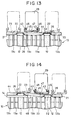
- Fig. 13 illustrating the moving path of the carriage 29 in the case wherein the surface of the sliding guide portion 44 of the paper pressing plate 21 is undulated
- the carriage 29 in the case where the cycle of undulation on the surface of the sliding guide 44 is approximately the same as the length of the flat portion of the sliding plate 45 in the direction of scanning of the carriage 29, the carriage 29 does not sink to the bottom of the concave portions of the undulation on the surface of the sliding guide portion 44, and the vertical movement of the center of gravity of the carriage 29 is suppressed.
- the cycle of undulation on the surface of the sliding guide portion 44 is 1/2 or less than the length of the flat portion of the sliding plate 45, the carriage 29 does not move vertically, and the head gap can be maintained constant.
- Fig. 14 which illustrates the state of printing work conducted on heavy printing paper 14 which is narrower that the width of the Paper pressing plate 21, an offset portion 48 is generated between the portion pinching the printing paper 14 and the portion that is not.
- the sliding plate 45 is inclined so as to follow the surface of the sliding guide portion 44 of the sliding plate 45, thus the shock generated upon the carriage 29 entering the offset portion 48 is extremely small, thereby assuring running stability of the carriage 29.
- both sides of the flat portion connected to the folded portions 46 of the sliding plate 45 so as to be an arc of a certain curvature, the catching of the sliding plate 45 on the sliding guide portion 44 of the sliding plate can be prevented beforehand, thus allowing for smooth sliding. From such a perspective, it is effective to form the sliding plate 45 of a material with a low friction coefficient, such as fluororesin.
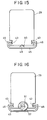
- a fulcrum portion 49 which protrudes downward to the side to the bottom plane of the carriage 29 is formed integrally to the center portion of the flat portion of the sliding plate 45 in the direction of scanning of the carriage 29.
- the upper tip of this fulcrum portion 49 is retained by a retaining concave portion 50 formed in the bottom plane of the carriage 29.
- the fulcrum portion 49 can be manufactured by means of press-forming of the sliding plate 45, or may be formed by adhesion of a separate member. The operation thereof is the same as the above-described embodiments shown in Figs. 12 through 14 in that the sliding plate 45 displaces centrally around the fulcrum portion 49.
- a printer head 28 is mounted to the carriage 29 and the sliding plate 45 of the carriage 29 comes into contact with the sliding guide portion 44 of the paper pressing plate 21, thus providing the head gap accurately, but this head gap can be arranged so as to capable of fine adjusting.
- an eccentric ring is rotatably attached to the bottom portion of the carriage 29 via a ring fixing screw 51 which extends in a direction parallel to the surface of the platen and at right angles to the direction of scanning of the carriage 29.
- This eccentric ring 52 is fit in an eccentric manner to the ring fixing screw 51, and the eccentric ring 52 can be fixed by means of operating the ring fixing screw 51 at a desired rotation position to the carriage 29.
- the lower edge of the eccentric ring 52 is located further lower than the lower bottom plane of the carriage 29, and thus the position of the flat portion of the sliding plate 45 can be finely adjusted in the upward and downward directions corresponding to the eccentricity of this eccentric ring 52.
- the lower edge of the eccentric ring 52 also serves as a fulcrum in the present invention, and is precisely the same as the earlier embodiment in that the sliding plate 45 displaces centrally around the lower edge of this eccentric ring 52.
- FIG. 17 The exterior view of a carriage 29 is shown in Fig. 17.
- the members which are of the same function as those of the earlier embodiments are denoted by the same reference numerals, and redundant description thereof will be omitted.
- 53 denotes an eccentric pin, and the smaller circumference portion 54 which is eccentric as compared to the larger circumference portion is rotatably fit to the lower portion of the carriage 29.
- the eccentric pin 53 can be fixed at a desired eccentric rotation position.
- 55 denotes an displacement lever, which is capable of displacement centrally around 56a to the carriage 29, with a pair of ribs 57 provided on one side pinching the greater circumference portion of the eccentric pin 53 and thus fixing to the position shown in the Figure.
- a shaft 55 is provided to the other edge of the displacement lever 55.
- 59 denotes a sliding plate, but unlike the earlier embodiments, is rotatably fit to the shaft 58 of the aforementioned displacement lever 55 at the center portion 59a.
- the folded portions 46 (Fig. 16) on both sides of the sliding plate 59 are done away with, with an extended portion 40 extended from the carriage 29 extended to the proximity of the sliding plate 59, thus restricting the amount of displacement of the sliding plate 59.
- rotating the eccentric pin 53 causes synchronous displacement of the displacement lever 55, thus the position of the flat portion of the sliding plate 59 can be finely adjusted in the upward and downward directions. Consequently, the spacing between the sliding plate 59 and the carriage extended portion 40 can be changed, so that the range of adjustment in the upward and downward directions of the sliding plate 59 can be adjusted.
- the sliding portion of the carriage has been made so as to displace in accordance with the surface form of the printing medium pressing member, so that even of there is existence of fine undulations on the surface of the printing medium pressing member the amplitude thereof is reduced, and the shock of riding up on the offset portion generated on the surface of the printing medium pressing member based on the edge of the printing medium is weakened, thus allowing for the scanning precision of the carriage to be maintained favorably.
- the sliding plate turns following the surface form of the medium pressing plate, so that there is no uneven contact of the sliding plate, thus inhibiting uneven wearing of the sliding plate.
- a printer apparatus includes a carriage for moving a printer head in a reciprocal manner, a carriage supporting member for guiding the movement of the carriage by slidably supporting the carriage using a sliding supporting member which slidably supports the carriage, and a displacement portion which is provided to the carriage and is capable of displacement along the surface of the sliding member within a plane which is vertical to the movement direction of the carriage, so that even if irregularities in height such as offsets exist in the sliding portion of the supporting member which slidably supports the carriage, stable running of the carriage can be achieved.
Landscapes
- Common Mechanisms (AREA)
- Ink Jet (AREA)
- Handling Of Cut Paper (AREA)
Applications Claiming Priority (9)
| Application Number | Priority Date | Filing Date | Title |
|---|---|---|---|
| JP5809396 | 1996-03-14 | ||
| JP58093/96 | 1996-03-14 | ||
| JP5809396 | 1996-03-14 | ||
| JP11078596 | 1996-05-01 | ||
| JP11078596 | 1996-05-01 | ||
| JP110785/96 | 1996-05-01 | ||
| JP4250397 | 1997-02-26 | ||
| JP9042503A JPH1016350A (ja) | 1996-03-14 | 1997-02-26 | プリント装置 |
| JP42503/97 | 1997-02-26 |
Publications (2)
| Publication Number | Publication Date |
|---|---|
| EP0795413A1 true EP0795413A1 (de) | 1997-09-17 |
| EP0795413B1 EP0795413B1 (de) | 2002-12-04 |
Family
ID=27291236
Family Applications (1)
| Application Number | Title | Priority Date | Filing Date |
|---|---|---|---|
| EP97104290A Expired - Lifetime EP0795413B1 (de) | 1996-03-14 | 1997-03-13 | Drucker |
Country Status (4)
| Country | Link |
|---|---|
| US (1) | US6250731B1 (de) |
| EP (1) | EP0795413B1 (de) |
| JP (1) | JPH1016350A (de) |
| DE (1) | DE69717520T2 (de) |
Cited By (1)
| Publication number | Priority date | Publication date | Assignee | Title |
|---|---|---|---|---|
| EP1053883A2 (de) * | 1999-05-14 | 2000-11-22 | Canon Kabushiki Kaisha | Tintenstrahlaufzeichnungsapparat |
Families Citing this family (12)
| Publication number | Priority date | Publication date | Assignee | Title |
|---|---|---|---|---|
| US6373601B1 (en) * | 1999-02-17 | 2002-04-16 | Microtek International, Inc. | Image scanner |
| JP2004122439A (ja) * | 2002-09-30 | 2004-04-22 | Brother Ind Ltd | キャリッジ及び画像形成装置 |
| US7380690B2 (en) * | 2003-01-17 | 2008-06-03 | Ricoh Company, Ltd. | Solution jet type fabrication apparatus, method, solution containing fine particles, wiring pattern substrate, device substrate |
| JP4930400B2 (ja) * | 2008-02-08 | 2012-05-16 | セイコーエプソン株式会社 | ヘッドユニット、液体噴射装置および液体噴射ヘッドの位置調整方法 |
| US20090309921A1 (en) * | 2008-06-16 | 2009-12-17 | Canon Kabushiki Kaisha | Recording apparatus |
| US8083316B2 (en) * | 2008-06-30 | 2011-12-27 | Lexmark International, Inc. | Printhead carrier with height-adjustable bearing mechanism for continuous adjustment of the printhead carrier position |
| JP5305006B2 (ja) * | 2008-11-06 | 2013-10-02 | セイコーエプソン株式会社 | 記録装置 |
| JP5696651B2 (ja) * | 2011-11-28 | 2015-04-08 | ブラザー工業株式会社 | インクジェット記録装置 |
| JP2014113765A (ja) * | 2012-12-11 | 2014-06-26 | Seiko Epson Corp | 画像記録装置 |
| US9067418B2 (en) | 2012-12-11 | 2015-06-30 | Seiko Epson Corporation | Image recording device |
| JP2017128070A (ja) | 2016-01-21 | 2017-07-27 | キヤノンファインテック株式会社 | キャリッジ装置 |
| WO2020167320A1 (en) * | 2019-02-15 | 2020-08-20 | Hewlett-Packard Development Company, L.P. | Contact members for slidable carriages |
Citations (5)
| Publication number | Priority date | Publication date | Assignee | Title |
|---|---|---|---|---|
| US4088215A (en) * | 1976-12-10 | 1978-05-09 | Ncr Corporation | Record media compensation means for printers |
| EP0467424A2 (de) * | 1987-03-02 | 1992-01-22 | EASTMAN KODAK COMPANY (a New Jersey corporation) | Vorrichtung zur Handhabung von Aufzeichnungsträgern für einen kompakten Drucker mit einer Vielzahl auf einem hin und her bewegbaren Schlitten angeordneten Druckköpfen |
| EP0623474A2 (de) * | 1993-05-03 | 1994-11-09 | Hewlett-Packard Company | Verfahren zum Ermitteln und Einregeln der Druckqualität in Thermofarbstrahldrucker |
| EP0650846A2 (de) * | 1993-10-29 | 1995-05-03 | Hewlett-Packard Company | Selbstanpassende Steuerung des Abstandes zwischen Druckkopf und Aufzeichnungsträger in Tintenstrahldruckern |
| GB2290753A (en) * | 1994-02-10 | 1996-01-10 | Seiko Epson Corp | Paper handling in ink jet printer. |
Family Cites Families (9)
| Publication number | Priority date | Publication date | Assignee | Title |
|---|---|---|---|---|
| US3990560A (en) * | 1972-08-04 | 1976-11-09 | Ncr Corporation | Automatic media thickness compensator for a printer |
| JPS60101054A (ja) * | 1983-11-08 | 1985-06-05 | Canon Inc | 液体噴射装置 |
| US5065169A (en) * | 1988-03-21 | 1991-11-12 | Hewlett-Packard Company | Device to assure paper flatness and pen-to-paper spacing during printing |
| US5168291A (en) | 1989-04-24 | 1992-12-01 | Canon Kabushiki Kaisha | Recording apparatus and ink cassette therefor |
| JPH0427571A (ja) * | 1989-09-22 | 1992-01-30 | Fuji Electric Co Ltd | インクジェット・プリンタ |
| DE69025124T2 (de) * | 1989-10-19 | 1996-07-04 | Seiko Epson Corp | Tintenstrahldrucker |
| US5291224A (en) | 1989-10-27 | 1994-03-01 | Canon Kabushiki Kaisha | Sheet feeding apparatus using pairs of spur rollers |
| JP2864140B2 (ja) | 1990-02-16 | 1999-03-03 | キヤノン株式会社 | 駆動伝達装置 |
| DE4041985A1 (de) * | 1990-12-21 | 1992-07-02 | Mannesmann Ag | Drucker, insbesondere matrixdrucker |
-
1997
- 1997-02-26 JP JP9042503A patent/JPH1016350A/ja active Pending
- 1997-03-11 US US08/815,427 patent/US6250731B1/en not_active Expired - Fee Related
- 1997-03-13 EP EP97104290A patent/EP0795413B1/de not_active Expired - Lifetime
- 1997-03-13 DE DE69717520T patent/DE69717520T2/de not_active Expired - Fee Related
Patent Citations (5)
| Publication number | Priority date | Publication date | Assignee | Title |
|---|---|---|---|---|
| US4088215A (en) * | 1976-12-10 | 1978-05-09 | Ncr Corporation | Record media compensation means for printers |
| EP0467424A2 (de) * | 1987-03-02 | 1992-01-22 | EASTMAN KODAK COMPANY (a New Jersey corporation) | Vorrichtung zur Handhabung von Aufzeichnungsträgern für einen kompakten Drucker mit einer Vielzahl auf einem hin und her bewegbaren Schlitten angeordneten Druckköpfen |
| EP0623474A2 (de) * | 1993-05-03 | 1994-11-09 | Hewlett-Packard Company | Verfahren zum Ermitteln und Einregeln der Druckqualität in Thermofarbstrahldrucker |
| EP0650846A2 (de) * | 1993-10-29 | 1995-05-03 | Hewlett-Packard Company | Selbstanpassende Steuerung des Abstandes zwischen Druckkopf und Aufzeichnungsträger in Tintenstrahldruckern |
| GB2290753A (en) * | 1994-02-10 | 1996-01-10 | Seiko Epson Corp | Paper handling in ink jet printer. |
Cited By (3)
| Publication number | Priority date | Publication date | Assignee | Title |
|---|---|---|---|---|
| EP1053883A2 (de) * | 1999-05-14 | 2000-11-22 | Canon Kabushiki Kaisha | Tintenstrahlaufzeichnungsapparat |
| EP1053883A3 (de) * | 1999-05-14 | 2000-11-29 | Canon Kabushiki Kaisha | Tintenstrahlaufzeichnungsapparat |
| US6659603B2 (en) | 1999-05-14 | 2003-12-09 | Canon Kabushiki Kaisha | Ink jet recording method and apparatus having platen with extrusions positioned in one-to-one correspondence with roller nips |
Also Published As
| Publication number | Publication date |
|---|---|
| US6250731B1 (en) | 2001-06-26 |
| JPH1016350A (ja) | 1998-01-20 |
| DE69717520D1 (de) | 2003-01-16 |
| DE69717520T2 (de) | 2003-04-17 |
| EP0795413B1 (de) | 2002-12-04 |
Similar Documents
| Publication | Publication Date | Title |
|---|---|---|
| EP0795413B1 (de) | Drucker | |
| US6059392A (en) | Apparatus for adjusting head gap depending upon the thickness of printing paper in ink jet printer | |
| US5564847A (en) | Media handling in an ink-jet printer having guide ribs | |
| JP4667300B2 (ja) | 記録装置 | |
| US20070272512A1 (en) | Belt conveyance unit and an image formation apparatus | |
| US10493648B2 (en) | Cutting device and printing apparatus | |
| US6682190B2 (en) | Controlling media curl in print-zone | |
| US8651603B2 (en) | Platen gap adjustment mechanism and printer | |
| US6089773A (en) | Print media feed system for an ink jet printer | |
| JP5327440B2 (ja) | キャリッジ、該キャリッジを備えた記録装置 | |
| JP3762155B2 (ja) | 排紙装置及びこれを備えた画像形成装置 | |
| US5087141A (en) | Combination pinch roller and carriage guide for printer | |
| EP0729843B1 (de) | Trägermechanismus für Druckmaterial für Tintenstrahldrucker | |
| CN1657300B (zh) | 打印装置 | |
| JP5127555B2 (ja) | 画像形成装置 | |
| US6869175B2 (en) | Recording apparatus | |
| EP1820656B1 (de) | Aufzeichnungsgerät | |
| EP0729842B1 (de) | Medientransport bei einem Tintenstrahldrucker | |
| JPH08108593A (ja) | 画像記録装置 | |
| US6000866A (en) | Printer with sheet curl straightening device | |
| JPH07237398A (ja) | プロッタ | |
| US20130286094A1 (en) | Printing apparatus | |
| JP2015058531A (ja) | 画像形成装置 | |
| KR100438739B1 (ko) | 잉크젯 프린터의 캐리어 이송 장치 | |
| JP2006043893A (ja) | 記録装置 |
Legal Events
| Date | Code | Title | Description |
|---|---|---|---|
| PUAI | Public reference made under article 153(3) epc to a published international application that has entered the european phase |
Free format text: ORIGINAL CODE: 0009012 |
|
| AK | Designated contracting states |
Kind code of ref document: A1 Designated state(s): DE FR GB IT |
|
| 17P | Request for examination filed |
Effective date: 19980203 |
|
| 17Q | First examination report despatched |
Effective date: 19991008 |
|
| GRAG | Despatch of communication of intention to grant |
Free format text: ORIGINAL CODE: EPIDOS AGRA |
|
| GRAG | Despatch of communication of intention to grant |
Free format text: ORIGINAL CODE: EPIDOS AGRA |
|
| GRAH | Despatch of communication of intention to grant a patent |
Free format text: ORIGINAL CODE: EPIDOS IGRA |
|
| GRAH | Despatch of communication of intention to grant a patent |
Free format text: ORIGINAL CODE: EPIDOS IGRA |
|
| GRAA | (expected) grant |
Free format text: ORIGINAL CODE: 0009210 |
|
| AK | Designated contracting states |
Kind code of ref document: B1 Designated state(s): DE FR GB IT |
|
| PG25 | Lapsed in a contracting state [announced via postgrant information from national office to epo] |
Ref country code: IT Free format text: LAPSE BECAUSE OF FAILURE TO SUBMIT A TRANSLATION OF THE DESCRIPTION OR TO PAY THE FEE WITHIN THE PRESCRIBED TIME-LIMIT;WARNING: LAPSES OF ITALIAN PATENTS WITH EFFECTIVE DATE BEFORE 2007 MAY HAVE OCCURRED AT ANY TIME BEFORE 2007. THE CORRECT EFFECTIVE DATE MAY BE DIFFERENT FROM THE ONE RECORDED. Effective date: 20021204 Ref country code: FR Free format text: LAPSE BECAUSE OF FAILURE TO SUBMIT A TRANSLATION OF THE DESCRIPTION OR TO PAY THE FEE WITHIN THE PRESCRIBED TIME-LIMIT Effective date: 20021204 |
|
| REG | Reference to a national code |
Ref country code: GB Ref legal event code: FG4D |
|
| REF | Corresponds to: |
Ref document number: 69717520 Country of ref document: DE Date of ref document: 20030116 |
|
| PLBE | No opposition filed within time limit |
Free format text: ORIGINAL CODE: 0009261 |
|
| STAA | Information on the status of an ep patent application or granted ep patent |
Free format text: STATUS: NO OPPOSITION FILED WITHIN TIME LIMIT |
|
| EN | Fr: translation not filed | ||
| 26N | No opposition filed |
Effective date: 20030905 |
|
| PGFP | Annual fee paid to national office [announced via postgrant information from national office to epo] |
Ref country code: GB Payment date: 20080326 Year of fee payment: 12 |
|
| PGFP | Annual fee paid to national office [announced via postgrant information from national office to epo] |
Ref country code: DE Payment date: 20080331 Year of fee payment: 12 |
|
| GBPC | Gb: european patent ceased through non-payment of renewal fee |
Effective date: 20090313 |
|
| PG25 | Lapsed in a contracting state [announced via postgrant information from national office to epo] |
Ref country code: DE Free format text: LAPSE BECAUSE OF NON-PAYMENT OF DUE FEES Effective date: 20091001 |
|
| PG25 | Lapsed in a contracting state [announced via postgrant information from national office to epo] |
Ref country code: GB Free format text: LAPSE BECAUSE OF NON-PAYMENT OF DUE FEES Effective date: 20090313 |