EP0794529B1 - Aufnahme- und Wiedergabegerät - Google Patents
Aufnahme- und Wiedergabegerät Download PDFInfo
- Publication number
- EP0794529B1 EP0794529B1 EP97103525A EP97103525A EP0794529B1 EP 0794529 B1 EP0794529 B1 EP 0794529B1 EP 97103525 A EP97103525 A EP 97103525A EP 97103525 A EP97103525 A EP 97103525A EP 0794529 B1 EP0794529 B1 EP 0794529B1
- Authority
- EP
- European Patent Office
- Prior art keywords
- signal
- recording
- reproducing
- data
- clock signal
- Prior art date
- Legal status (The legal status is an assumption and is not a legal conclusion. Google has not performed a legal analysis and makes no representation as to the accuracy of the status listed.)
- Expired - Lifetime
Links
Images


Classifications
-
- G—PHYSICS
- G11—INFORMATION STORAGE
- G11B—INFORMATION STORAGE BASED ON RELATIVE MOVEMENT BETWEEN RECORD CARRIER AND TRANSDUCER
- G11B20/00—Signal processing not specific to the method of recording or reproducing; Circuits therefor
- G11B20/10—Digital recording or reproducing
- G11B20/10009—Improvement or modification of read or write signals
Definitions
- the present invention relates to a recording and reproducing apparatus having a simultaneous reproducing function in which the reproducing operation is conducted substantially simultaneously with the recording operation.
- broadcasting VCR In the case of a video cassette recorder for a broadcasting station (hereinafter, referred to as "broadcasting VCR"), it is difficult in many cases to conduct the image recording over again. Therefore, a failure in recording must be prevented from occurring. In order to prevent such a failure from occurring, a broadcasting VCR must have a simultaneous reproducing function in which the recording operation and the operation of reproducing the recorded contents are conducted at the substantially same time, thereby enabling the recorded contents to be checked.
- JP-A-60052902 discloses a recording and reproducing apparatus according to the preamble of claim 1.
- the object of the present invention is achieved by the recording and reproducing apparatus of claim 1.
- the reproducing operation can be conducted simultaneously with the recording operation in an apparatus of a reduced size.
- the present invention even in an apparatus of the type hardly capable of sufficient electromagnetic separation between recording and reproduced signals, such as a small broadcasting VCR with a small size rotary cylinder unit, it is possible to realize a simultaneous reproducing function in which crosstalk components leaking from the recording signal into the reproduced signal are reduced in level.
- FIGs. 1 to 3 show a magnetic recording and reproducing apparatus which is Embodiment 1 of a recording and reproducing apparatus not part of the present invention.
- a pair of recording heads and a pair of reproducing heads are mounted on a small rotary cylinder, and digital data are recorded onto and reproduced from a magnetic tape which is slantly wound on the rotary cylinder and travels thereon.
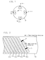
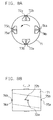
- FIG. 1 is a diagram showing the head arrangement of the rotary cylinder of the magnetic recording and reproducing apparatus of Embodiment 1.
- the rotary cylinder 31 is small in size or has a diameter of about 20 mm, and rotates in a counterclockwise direction as shown in FIG. 1.
- First and second recording heads 4 and 14, and first and second reproducing heads 5 and 15 are arranged on the rotary cylinder 31.
- the magnetic tape travels with being slantly wrapped in a zone corresponding to a semicircle (180 degrees) of the rotary cylinder 31.
- FIG. 2 is a diagram showing positional relationships among recording tracks on the magnetic tape 40 and the heads.
- plural tracks 41a, 41b, 42a, 42b, 43a, 43b, ⁇ are slantly formed on the magnetic tape 40.
- the tracks 41a, 42a, and 43a are tracks which have been already recorded on the magnetic tape 40 by the first recording head 4, and the tracks 41b, 42b, and 43b are tracks which have been already recorded on the magnetic tape 40 by the second recording head 14.
- the track 44a is currently being recorded by the first recording head 4.
- the first reproducing head 5 traces the track 44a and conducts the reproducing operation at a timing which is slightly later than that of the recording operation on the track by the first recording head 4. Therefore, the magnetic recording and reproducing apparatus of Embodiment 1 can conduct the recording and reproducing operations at the substantially same time, so that the recorded contents can be checked.
- the tracks 41b, 42b, and 43b which are recorded by the second recording head 14 are subjected to the reproducing operation by the second reproducing head 15 substantially simultaneously with the recording operation.
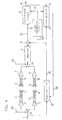
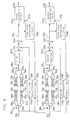
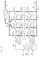
- FIG. 3 is a block diagram showing the signal system in the magnetic recording and reproducing apparatus of Embodiment 1.
- the first and second recording heads 4 and 14 are mounted on the rotary cylinder 31 and alternatingly make contact with the magnetic tape 40 so as to conduct the recording operation thereon as shown in FIG. 1 mentioned above.
- a recording signal 1 containing digital data to be recorded is supplied to a recording changeover switch 51 which is controlled by a recording head switch signal 29 synchronized with the rotary cylinder 31.
- the recording changeover switch 51 is connected to the upper terminal in FIG. 3.
- the signal which is to be recorded and is supplied through the recording changeover switch 51 is amplified by a first recording amplifier 2.
- the signal which is to be recorded and has been amplified is guided to the first recording head 4 on the rotary cylinder 31 through a first recording rotary-transformer 3 and then recorded onto the magnetic tape 40.
- the recording changeover switch 51 is connected to the lower terminal in FIG. 3.
- the signal which is to be recorded and is supplied through the recording changeover switch 51 is guided to the second recording head 14 on the rotary cylinder 31 through a second recording amplifier 12 and a second recording rotary-transformer 13 and then recorded onto the magnetic tape 40.
- the first and second reproducing heads 5 and 15 are mounted on the rotary cylinder 31 and alternatingly make contact with the magnetic tape 40 so as to conduct the reproducing operation thereon simultaneously with the above-mentioned recording operation.
- a reproducing changeover switch 61 shown in FIG. 3 is controlled by a reproducing head switch signal 30 which is synchronized with the rotary cylinder 31. During a period when the first reproducing head 5 makes contact with the magnetic tape 40, the reproducing changeover switch 61 is connected to the upper terminal in FIG. 3, and, during a period when the second reproducing head 15 makes contact with the magnetic tape 40, connected to the lower terminal in FIG. 3.
- a signal which has been reproduced by the first reproducing head 5 on the rotary cylinder 31 passes through a first reproducing rotary-transformer 6 and is then amplified by a first reproducing amplifier 7.
- the amplified signal is supplied to an equalizer 9 through the reproducing changeover switch 61.
- a signal which has been reproduced by the second reproducing head 15 on the rotary cylinder 31 passes through a second reproducing rotary-transformer 16 and is then amplified by a second reproducing amplifier 17.
- the amplified signal is supplied to the equalizer 9 through the reproducing changeover switch 61.
- the equalizer 9 the frequency characteristics of the system ranging from the recording operation to the reproducing operation are corrected, so that the reproduced signal is equalized in order to enable digital codes to be discriminated.
- the equalized signal is supplied to a subtractor 8 serving as the operating means.
- An equalized signal 20 which is output from the subtractor 8 is supplied to a clock reproducing circuit 22.
- the clock reproducing circuit 22 outputs a clock signal 23 synchronized with the recorded data.
- the equalized signal 20 is supplied also to a discriminant circuit 21.
- the codes of the data are subjected to discrimination at the timing of the clock signal 23, and the data is then output as a reproduced data 24 from the discriminant circuit 21.
- the signals which are reproduced from the magnetic tape 40 by the first and second reproducing heads 5 and 15 are very weak.
- the current levels of the reproduced signals are lower by about 70 dB than the recording currents respectively flowing through the first and second recording heads 4 and 14.
- the recording and reproducing heads and the rotary-transformers are proximately disposed on the small rotary cylinder 31 of a diameter of about 20 mm. Consequently, crosstalk in which a recording signal leaks into a reproduced signal occurs in the magnetic recording and reproducing apparatus of Embodiment 1.
- the crosstalk from a recording signal to a reproduced signal occurs through many paths.
- such paths include those from the first or second recording head 4 or 14 to the first or second reproducing head 5 or 15, from the first or second recording rotary-transformer 3 or 13 to the first or second reproducing rotary-transformer 6 or 16, and from wirings between the recording rotary-transformers and the recording heads to wirings between the reproducing rotary-transformers and the reproducing heads.
- the crosstalk components which finally leak into the output signal of the equalizer 9 through these many paths can be deemed as a signal which is obtained by providing the recording signal 1 with frequency characteristics based on a specific transfer function. Therefore, the crosstalk components can be artificially generated by applying the transfer function to the recording signal 1.
- the magnetic recording and reproducing apparatus of Embodiment 1 is provided with a filter 32 serving as the filtering means.
- the filter 32 is a transversal type filter, receives the recording signal 1 as an input signal, and has frequency characteristics which are similar to a transfer function of the crosstalk components in the system ranging from the recording signal 1 to the output of the equalizer 9.
- the output of the filter 32 is a pseudo crosstalk signal 26 which is a signal of the crosstalk components artificially generated. Therefore, the crosstalk components leaking into the reproduced signal are canceled by subtracting the pseudo crosstalk signal 26 from the output of the equalizer 9 in the subtractor 8 serving as the operating means.
- crosstalk interference is largely reduced. Consequently, the magnetic recording and reproducing apparatus of Embodiment 1 can be configured as a small apparatus in which reproduced data can be correctly discriminated without being affected by crosstalk components and which has a simultaneous reproducing function.
- Embodiment 1 although the small rotary cylinder unit in which separation between the recording and reproduced signals is hardly conducted by electromagnetic means is used, crosstalk interference applied to the reproduced signal can be eventually largely reduced by subtracting the pseudo crosstalk components which are artificially generated, from the reproduced signal. Accordingly, the recording and reproducing apparatus of Embodiment 1 can conduct the reproducing operation substantially simultaneously with the recording operation, thereby enabling the reproduction to be conducted highly accurately.
- the magnetic recording and reproducing apparatus of Embodiment 2 comprises a pair of recording heads and a pair of reproducing heads which are mounted on a small rotary cylinder as shown in FIGs. 1 and 2, and digital data are recorded onto and reproduced from a magnetic tape which is slantly wound on the rotary cylinder and travels thereon.
- the magnetic recording and reproducing apparatus of Embodiment 2 is different from the above-mentioned Embodiment 1 in the method of suppressing crosstalk in the signal system. This method will be mentioned.
- FIG. 4 is a signal system diagram of the magnetic recording and reproducing apparatus of Embodiment 2.
- portions having the same function as those of Embodiment 1 are designated by the same reference numerals, and their description is omitted.
- Embodiment 4 is different from Embodiment 1 shown in FIG. 3 in that an adaptive filter 25 is used as the adaptive filtering means in order to obtain the pseudo crosstalk signal 26, and that the embodiment comprises error detecting means consisting of an error detector 27 and the like in order to obtain an error signal 28 which is supplied to the adaptive filter 25.
- an adaptive filter 25 is used as the adaptive filtering means in order to obtain the pseudo crosstalk signal 26
- the embodiment comprises error detecting means consisting of an error detector 27 and the like in order to obtain an error signal 28 which is supplied to the adaptive filter 25.
- error detecting means consisting of an error detector 27 and the like in order to obtain an error signal 28 which is supplied to the adaptive filter 25.
- the error detecting means is configured with the discriminant circuit 21, the clock reproducing circuit 22, and the error detector 27.
- the equalized signal 20 which is an output of the subtractor 8 is supplied to the discriminant circuit 21 serving as discriminating means, the clock reproducing circuit 22, and the error detector 27.
- the clock reproducing circuit 22 outputs the clock signal 23 synchronized with the data.
- the clock signal 23 is supplied to the discriminant circuit 21 and the error detector 27.
- the discriminant circuit 21 discriminates the codes of the data at the timing of the clock signal 23, and outputs the reproduced data 24. Furthermore, the discriminant circuit supplies a reference signal 45 which will be mentioned later, to the error detector 27.
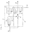
- FIG. 5 is a block diagram specifically showing an example of the discriminant circuit 21 and the error detector 27.
- the discriminant circuit 21 is configured with a comparator 46 and a latch circuit 47.
- the comparator 46 receives the equalized signal 20 and a threshold level 33, and outputs a result of comparison of the signals as the reference signal 45.
- An example of relationships among the eye pattern of the equalized signal 20, the threshold level 33, and the reference signal 45 will be mentioned with reference to FIG. 6.
- FIG. 6 shows the eye pattern of the equalized signal 20.
- the equalized signal 20 has ideally an amplitude of A or -A.
- the equalized signal 20 is actually caused not to pass the same point but to have deflection of a certain degree, by noises entering from the magnetic tape, the head system, and the like, or crosstalk from the recording signal.
- the threshold level 33 supplied to the comparator 46 is set to be an intermediate value between the amplitudes A and -A as shown in FIG. 6.
- the comparator 46 compares the threshold level 33 with the equalized signal 20. If the equalized signal 20 is larger than the threshold level 33, the comparator outputs the amplitude A as the reference signal 45, and, if the equalized signal 20 is smaller than the threshold level 33, outputs the amplitude -A.
- the reference signal 45 output from the comparator 46 is supplied to the latch circuit 47.
- the latch circuit 47 latches the data discrimination time synchronized with the data at the timing of the clock signal 23, and outputs the reproduced data 24.
- the error detector 27 is configured with a subtractor 49 serving as the operating means, and a sample and hold circuit 50.
- the subtractor 49 outputs the amplitude of the difference which is obtained by subtracting the reference signal 45 from the equalized signal 20.
- the value of the amplitude is held in the sample and hold circuit 50 at the timing of the clock signal 23.
- the output of the sample and hold circuit 50 indicates the error between the amplitude of the equalized signal 20 at the data discrimination time and the value which the signal should originally have.
- the output is used as the error signal 28.
- the error signal 28 output from the error detector 27 is supplied to the adaptive filter 25.
- the adaptive filter 25 receives also the recording signal 1 which is a signal to be recorded.
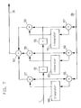
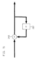
- FIG. 7 is a block diagram specifically showing an example of the adaptive filter 25.
- the adaptive filter 25 comprises of a 3-tap transversal type filter and operates so that the root mean square of the error signal 28 is always minimum.
- the adaptive filter 25 shown in FIG. 7 has first and second delay circuits 55 and 56 which serve as delaying means.
- the first and second delay circuits 55 and 56 delay the recording signal 1 by a one-bit period T. Therefore, the recording signal 1 is sequentially delayed by the first and second delay circuits 55 and 56.
- the adaptive filter 25 further has multipliers 65, 66, and 67 which serve as multiplying means.
- the three multipliers 65, 66, and 67 constitute the first multiplying means.
- the error signal 28 is supplied to one input of each of the multipliers 65, 66, and 67. As shown in FIG. 7, the recording signal 1, the output signal of the first delay circuit 55, and the output signal of the second delay circuit 56 are supplied to the other inputs of the multipliers 65, 66, and 67, respectively.
- the output signals of the multipliers 65, 66, and 67 are supplied to integrators 68, 69, and 70 serving as the integrating means, respectively, so that the output signals of the multipliers 65, 66, and 67 are integrated.
- the adaptive filter 25 has three multipliers 57, 58, and 59 to which the output signals of the integrators 68, 69, and 70 are supplied, respectively.
- the three multipliers 57, 58, and 59 constitute the second multiplying means.
- the recording signal 1 is supplied to one input of the multiplier 57, the output signal of the first delay circuit 55 to that of the multiplier 58, and the output signal of the second delay circuit 56 to that of the multiplier 59.
- the output signals of the multipliers 57, 58, and 59 are supplied to an adder 60 which serves as the operating means, and the total sum of the signals is output as the pseudo crosstalk signal 26.
- each of these multipliers can be realized by a switch circuit which switches over the manners of the output operation, i.e., the such output operation that the one input is output as it is, or that the one input is inverted and then output, depending on the digital codes of the recording signal 1, etc. that are the signals supplied to the other input.
- the signal component included in the output is indicated by s, the crosstalk components leaking from the recording signal 1 into the reproduced signal by x, and the noise components from the tape and the like by n.
- the pseudo crosstalk signal 26 is indicated by y.
- the characteristics of the adaptive filter 25 are changed so that the average of the first term of the right side of expression (3) with respect to time i is minimum.
- the average of the second term of the right side zero because the average of the noise components n is zero.
- the third term of the right side is independent from the pseudo crosstalk signal y, and therefore, by selecting that the time average of expression (3) is set to be minimum, this results in that the pseudo crosstalk signal 26 is optimally approximated to the crosstalk signal leaking into the reproduced signal.
- the tap coefficient C j can be obtained by time-integrating a product of the error signal (e i ) at time i and the recording signal (r i-j ) at time i-j.
- the above-mentioned principle is embodied in the adaptive filter 25 shown in FIG. 7.
- the adaptive filter 25 of Embodiment 2 therefore, its characteristics are changed so that the pseudo crosstalk signal 26 always optimally approximates to the crosstalk component leaking into the reproduced signal in the meaning of minimizing the root mean square error.
- the pseudo crosstalk signal 26 is subtracted in the subtractor 8 from the output signal of the equalizer 9, whereby the crosstalk components leaking into the reproduced signal are canceled so as to be largely reduced.
- the reproduced signal consisting of digital data can be correctly discriminated without being affected by the crosstalk components and a simultaneous reproducing function can be realized.
- Embodiment 2 of the present invention in addition to the same effects as those of the above-mentioned Embodiment 1, a pseudo crosstalk signal can be always adaptively generated. Even when the condition of crosstalk is changed in accordance with the rotation phase of the rotary cylinder or by changes in properties due to changes in temperature or with ages of the heads and electrical parts, simultaneous reproduction can be always conducted under the best conditions.
- the above-mentioned magnetic recording and reproducing apparatus of Embodiment 2 is an example in which the adaptive filtering means is configured by a 3-tap transversal type filter.
- the present invention is not restricted to this configuration.
- the filter may have taps of a larger number. This allows the pseudo crosstalk signal to more correctly approximate to the crosstalk component, with the result that the effect of reducing crosstalk can be further enhanced.
- the adaptive filtering means may be configured so that a fixed filter portion in which characteristics are always fixed, and a variable filter portion in which characteristics are adequately changed in accordance with the condition of crosstalk are cascade-connected. According to this configuration, even in an apparatus of a small circuit scale, the pseudo crosstalk signal can be correctly approximated to crosstalk components and adequately follow the change in crosstalk.
- the above-mentioned magnetic recording and reproducing apparatus of Embodiment 2 is an example in which the characteristics are changed by the adaptive filtering means with using the root mean square error so that the pseudo crosstalk signal always optimally approximates to a crosstalk signal leaking into the reproduced signal.
- the present invention is not restricted to this, and the apparatus may be configured so that, for example, the absolute value or the maximum value of the difference between the pseudo crosstalk signal and crosstalk components leaking into the reproduced signal is reduced.
- the above-mentioned magnetic recording and reproducing apparatus of Embodiment 2 is an example in which the error detecting means detects an error from the output signal of the equalizer and the reference signal of the discriminant circuit.
- the present invention is not restricted to this example.
- the output signal of the equalizer may be used as the error information, or the error information may be obtained from the reproduced signal which has not yet been subjected equalization.
- Embodiment 3 of the recording and reproducing apparatus of the present invention is similar in configuration to Embodiment 1 mentioned above, except that Embodiment 3 has a two-channel system in which two recording heads simultaneously conduct the recording operation and two reproducing heads simultaneously conduct the reproducing operation in order to realize the recording and reproducing operations at a higher data rate.
- FIG. 8 is a diagram showing the head arrangement of a rotary cylinder 71 of the magnetic recording and reproducing apparatus of Embodiment 3.
- (A) is a plan view of the rotary cylinder 71
- (B) is a schematic side view of the rotary cylinder 71.
- the rotary cylinder 71 is small in size or has a diameter of about 20 mm, and rotates in a counterclockwise direction as indicated by the arrow in (A) of FIG. 8.
- the rotary cylinder 71 has four recording heads. That is, a first recording head 72a, a second recording head 72b, a third recording head 73a, and a fourth recording head 73b are arranged on the rotary cylinder 71.
- the rotary cylinder 71 has four reproducing heads. That is, a first reproducing head 74a, a second reproducing head 74b, a third reproducing head 75a, and a fourth reproducing head 75b are arranged on the rotary cylinder 71. As shown in the side view of (B) of FIG. 8, heads which are adjacent to each other, for example, the first and second recording heads 72a and 72b are positioned so that their gaps are shifted from each other in the height direction by a distance corresponding to one track pitch. The magnetic tape travels with being slantly wrapped in a zone corresponding to a semicircle (180 degrees) of the rotary cylinder 71.
- FIG. 9 is a diagram showing positional relationships between recording tracks on the magnetic tape 82 and the heads.
- tracks are slantly formed on the magnetic tape 82 by the recording heads.
- Tracks 80a, 80b, 80c, and 80d shown in FIG. 9 have been already recorded by the first recording head 72a, the second recording head 72b, the third recording head 73a, and the fourth recording head 73b, respectively.
- Tracks 81a and 81b are currently recorded by the first and second recording heads 72a and 72b, respectively.
- the first and second reproducing heads 74a and 74b trace the tracks 81a and 81b with a slight delay with respect to the first and second recording heads 72a and 72b, respectively, so as to conduct the reproducing operation. Therefore, the magnetic recording and reproducing apparatus of Embodiment 3 can conduct the recording and reproducing operations at the substantially same time, so that the recorded contents can be checked.
- the tracks which are recorded by the third and fourth recording heads 73a and 73b are subjected to the reproducing operation by the third and fourth reproducing heads 75a and 75b substantially simultaneously with the recording operation.
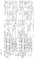
- FIG. 10 is a diagram of the signal system in the magnetic recording and reproducing apparatus of Embodiment 3.
- the recording signal containing digital data to be recorded is previously split into two systems so as to be supplied as first and second recording signals 83a and 83b.
- the first recording signal 83a is supplied to a first recording changeover switch 86a which is controlled by a first recording head switch signal 84a synchronized with the rotary cylinder 71.
- the first recording changeover switch 86a is connected to the upper terminal in FIG. 10.
- the signal which is to be recorded and is supplied through the first recording changeover switch 86a is amplified by a first recording amplifier 88a.
- the signal which is to be recorded and has been amplified is guided to the first recording head 72a on the rotary cylinder 71 through a first recording rotary-transformer 89a and then recorded onto the magnetic tape 82.
- the first recording changeover switch 86a is connected to the lower terminal in FIG. 10.
- the signal which is to be recorded and is supplied through the first recording changeover switch 86a is guided to the third recording head 73a on the rotary cylinder 71 through a third recording amplifier 94a and a third recording rotary-transformer 95a and then recorded onto the magnetic tape 82.
- the second recording signal 83b is supplied to a second recording changeover switch 86b which is controlled by a second recording head switch signal 84b synchronized with the rotary cylinder 71.
- the second recording changeover switch 86b is connected to the upper terminal in FIG. 10.
- the signal which is to be recorded and is supplied through the second recording changeover switch 86b is amplified by a second recording amplifier 88b.
- the signal which is to be recorded and has been amplified is guided to the second recording head 72b on the rotary cylinder 71 through a second recording rotary-transformer 89b and then recorded onto the magnetic tape 82.
- the second recording changeover switch 86b is connected to the lower terminal in FIG. 10.
- the signal which is to be recorded and is supplied through the second recording changeover switch 86b is guided to the fourth recording head 73b on the rotary cylinder 71 through a fourth recording amplifier 94b and a fourth recording rotary-transformer 95b and then recorded onto the magnetic tape 82.
- a first reproducing changeover switch 87a is controlled by a first reproducing head switch signal 85a which is synchronized with the rotary cylinder 71. Therefore, during a period when the first reproducing head 74a makes contact with the magnetic tape 82, therefore, the first reproducing changeover switch 87a is connected to the upper terminal in FIG. 10, and, during a period when the third reproducing head 75a makes contact with the magnetic tape 82, it is connected to the lower terminal.
- a signal which has been reproduced by the first reproducing head 74a on the rotary cylinder 71 passes through a first reproducing rotary-transformer 92a and is then amplified by a first reproducing amplifier 93a.
- the amplified signal is supplied to a first equalizer 100a through the first reproducing changeover switch 87a.
- a signal which has been reproduced by the third reproducing head 75a passes through a third reproducing rotary-transformer 98a and is then amplified by a third reproducing amplifier 99a.
- the amplified signal is supplied to the first equalizer 100a through the first reproducing changeover switch 87a.
- the frequency characteristics of the system ranging from the recording operation to the reproducing operation are corrected, and the signal is equalized in order to enable digital codes of the data to be discriminated.
- the signal which has been equalized in the first equalizer 100a passes through first and second subtractors 101a and 102a serving as the operating means, to be formed as an equalized signal 103a.
- the equalized signal 103a is supplied to a first clock reproducing circuit 106a.
- the first clock reproducing circuit 106a outputs a clock signal 107a synchronized with the data.
- the equalized signal 103a is supplied also to a first discriminant circuit 104a.
- the first discriminant circuit 104a discriminates the digital codes of the data at the timing of the clock signal 107a, and outputs a first reproduced data 105a.
- a second reproducing changeover switch 87b is controlled by a second reproducing head switch signal 85b which is synchronized with the rotary cylinder 71.
- the second reproducing changeover switch 87b is connected to the upper terminal, and, during a period when the fourth reproducing head 75b makes contact with the magnetic tape 82, it is connected to the lower terminal.
- a signal which has been reproduced by the second reproducing head 74b on the rotary cylinder 71 passes through a second reproducing rotary-transformer 92b and is then amplified by a second reproducing amplifier 93b.
- the amplified signal is supplied to a second equalizer 100b through the second reproducing changeover switch 87b.
- a signal which has been reproduced by the fourth reproducing head 75b passes through a fourth reproducing rotary-transformer 98b and is then amplified by a fourth reproducing amplifier 99b.
- the amplified signal is supplied to the second equalizer 100b through the second reproducing changeover switch 87b.
- the second equalizer 100b the frequency characteristics of the system ranging from the recording operation to the reproducing operation are corrected, and the signal is equalized in order to enable digital codes of the data to be discriminated.
- the signal which has been equalized in the second equalizer 100b passes through third and fourth subtractors lOlb and 102b serving as the operating means, to be formed as an equalized signal 103b.
- the equalized signal 103b is supplied to a second clock reproducing circuit 106b.
- the second clock reproducing circuit 106b outputs a clock signal 107b synchronized with the data.
- the equalized signal 103b is supplied also to a second discriminant circuit 104b.
- the second discriminant circuit 104b discriminates the digital codes of the data at the timing of the clock signal 107b, and outputs a second reproduced data 105b.
- the signal which is reproduced from the magnetic tape 82 by the first reproducing head 74a, the second reproducing head 74b, the third reproducing head 75a, or the fourth reproducing head 75b is very weak.
- the current level of the reproduced signal is lower by about 70 dB than the recording current flowing through the first recording head 72a, the second recording head 72b, the third recording head 73a, or the fourth recording head 73b.
- the recording and reproducing heads and the rotary-transformers are proximately disposed on the small rotary cylinder 71 of a diameter of about 20 mm. Consequently, there occurs crosstalk in which a recording signal leaks into a reproduced signal.
- the first and second recording heads 72a and 72b simultaneously operate as shown in FIG. 9. Therefore, the reproduced signals of the first and second reproducing heads 74a and 74b simultaneously undergo crosstalk interference due to the two recording signals, i.e., the first and second recording signals 83a and 83b.
- the reproduced signals simultaneously undergo crosstalk interference due to the two recording signals.
- the first recording signal 83a is supplied to a first filter 110a serving as the filtering means.
- the first filter 110a has characteristics which are similar to a transfer function of crosstalk components in the system ranging from the first recording signal 83a to the output of the first equalizer 100a. According to this configuration, the output of the first filter 110a is a first pseudo crosstalk signal 108a which is obtained by artificially generating crosstalk components from the first recording signal 83a.
- the second recording signal 83b is supplied to a third filter 111a serving as the filtering means.
- the third filter 111a has characteristics which are similar to a transfer function of crosstalk components in the system ranging from the second recording signal 83b to the output of the first equalizer 100a. According to this configuration, the output of the third filter 111a is a third pseudo crosstalk signal 109a which is obtained by artificially generating crosstalk components from the second recording signal 83b.
- the first and second subtractors lOla and 102a serving as the operating means crosstalk components of both two systems leaking into the reproduced signal are canceled by subtracting the first and third pseudo crosstalk signals 108a and 109a from the output signal of the first equalizer 100a.
- crosstalk interference is largely reduced. Consequently, the first reproduced data 105a output from the first discriminant circuit 104a consists of data in which digital codes are correctly discriminated without being affected by crosstalk components.
- the second and fourth filters 110b and lllb output second and fourth pseudo crosstalk signals 108b and 109b, respectively.
- the third and fourth subtractors 101b and 102b serving as the operating means function in the same manner as the first and second subtractors 101a and 102a, so that crosstalk components leaking into the output of the second equalizer 100b are subtracted and the crosstalk components of both the two systems leaking into the reproduced signal are canceled, whereby crosstalk interference is largely reduced.
- the second reproduced data 105b output from the second discriminant circuit 104b consists of data in which digital codes are correctly discriminated without being affected by crosstalk components. Consequently, the magnetic recording and reproducing apparatus of Embodiment 3 results in an apparatus having a highly accurate simultaneous reproducing function.
- the magnetic recording and reproducing apparatus of Embodiment 3 of the present invention since the magnetic recording and reproducing apparatus of Embodiment 3 of the present invention has a two-channel system in which the recording and reproducing operations are conducted at a higher data rate, crosstalk phenomena due to the two systems are concurrently generated. In the magnetic recording and reproducing apparatus of Embodiment 3, however, crosstalk of the two systems is canceled, and crosstalk interference applied to the reproduced signal is eventually largely reduced. Consequently, the magnetic recording and reproducing apparatus of Embodiment 3 can be configured as an apparatus which is small in size but can conduct simultaneous reproduction.
- Embodiment 3 the two-channel configuration in which the two recording heads simultaneously conduct the recording operation and the two reproducing heads simultaneously conduct the reproducing operation has been mentioned.
- the recording and reproducing apparatus of the present invention is not restricted to this configuration. In order to conduct the recording and reproducing operations at a further higher data rate, the number of channels may be increased. Also in this case, the apparatus can be configured in a similar manner.
- the magnetic recording and reproducing apparatus of Embodiment 4 has the two-channel configuration in which the two recording heads simultaneously conduct the recording operation and the two reproducing heads simultaneously conduct the reproducing operation, but is different from the magnetic recording and reproducing apparatus of Embodiment 3 in that adaptive filters similar to those used in the magnetic recording and reproducing apparatus of Embodiment 2 are used in the signal systems in order to generate pseudo crosstalk signals.
- FIG. 11 is a diagram of the signal system in the magnetic recording and reproducing apparatus of Embodiment 4. Portions having the same function as those of the magnetic recording and reproducing apparatus of Embodiment 3 are designated by the same reference numerals, and their description is omitted.
- Embodiment 112a a first adaptive filter 112a, a second adaptive filter 112b, a third adaptive filter 113a, and a fourth adaptive filter 113b are used as the adaptive filtering means in order to obtain the first pseudo crosstalk signal 108a, the second pseudo crosstalk signal 108b, the third pseudo crosstalk signal 109a, and the fourth pseudo crosstalk signal 109b.
- Embodiment 4 is different from Embodiment 3 in that, in order to obtain first and second error signals 116a and 116b which are supplied to the adaptive filters, two error detecting means respectively comprising first and second error detectors 114a and 114b are disposed.
- first error detecting means comprises the first discriminant circuit 104a, the first clock reproducing circuit 106a, and the first error detector 114a.
- the equalized signal 103a which is the output of the second subtractor 102a is supplied to the first discriminant circuit 104a serving as discriminating means, the first clock reproducing circuit 106a, and the first error detector 114a.
- the first clock reproducing circuit 106a outputs the clock signal 107a synchronized with the data.
- the clock signal 107a is supplied to the first discriminant circuit 104a and the first error detector 114a.
- the first discriminant circuit 104a discriminates the digital codes of the data at the timing of the clock signal 107a, outputs a first reproduced data 105a, and supplies a reference signal 115a which will be mentioned later, to the first error detector 114a.
- the first discriminant circuit 104a and the first error detector 114a are configured in the same manner as those used in Embodiment 2 and shown in FIG. 5, and hence their description is omitted. However, Embodiment 4 is configured so that the error between the amplitude of the equalized signal 103a at the data discrimination time and the value which the signal should originally have is output as the first error signal 116a from the first error detector 114a.
- the first error signal 116a output from the first error detector 114a is supplied to the first and third adaptive filters 112a and 113a which serve as the adaptive filtering means.
- the first recording signal 83a is supplied to the first adaptive filter 112a and the second recording signal 83b is supplied to the third adaptive filter 113a.
- the first adaptive filter 112a outputs the first pseudo crosstalk signal 108a which optimally approximates to frequency characteristics of crosstalk components of the system ranging from the first recording signal 83a to the first equalizer 100a.
- the third adaptive filter 113a outputs the third pseudo crosstalk signal 109a which optimally approximates to frequency characteristics of crosstalk components of the system ranging from the second recording signal 83b to the first equalizer 100a.
- the configuration and operation of the first or third adaptive filter 112a or 113a are the same as those of the adaptive filter 25 used in Embodiment 2 and shown in FIG. 7, and hence their description is omitted.
- the first and second subtractors lOla and 102a serving as the operating means crosstalk components of both the two systems leaking into the reproduced signal are canceled by subtracting the first and third pseudo crosstalk signals 108a and 109a from the output signal of the first equalizer 100a.
- crosstalk interference is largely reduced. Consequently, the first reproduced data 105a consists of data in which digital codes are correctly discriminated without being affected by crosstalk components.
- second error detecting means comprises the second discriminant circuit 104b, the second clock reproducing circuit 106b, and the second error detector 114b.
- the equalized signal 103b which is the output of the fourth subtractor 102b is supplied to the second discriminant circuit 104b serving as discriminating means, the second clock reproducing circuit 106b, and the second error detector 114b.
- the second clock reproducing circuit 106b outputs the clock signal 107b synchronized with the data.
- the clock signal 107b is supplied to the second discriminant circuit 104b and the second error detector 114b.
- the second discriminant circuit 104b discriminates the codes of the data at the timing of the clock signal 107b, outputs a second reproduced data 105b, and supplies a reference signal 115b to the second error detector 114b.
- the second error detector 114b outputs the error between the amplitude of the equalized signal 103b at the data discrimination time and the value which the signal should originally have, as the error signal 116b.
- the error signal 116b output from the second error detector 114b is supplied to the second and fourth adaptive filters 112b and 113b which serve as the adaptive filtering means.
- the first recording signal 83a is supplied to the second adaptive filter 112b and the second recording signal 83b is supplied to the fourth adaptive filter 113b.
- the second adaptive filter 112b outputs the second pseudo crosstalk signal 108b which optimally approximates to frequency characteristics of crosstalk components of the system ranging from the first recording signal 83a to the second equalizer 100b.
- the fourth adaptive filter 113b outputs the fourth pseudo crosstalk signal 109b which optimally approximate to frequency characteristics of crosstalk components of the system ranging from the second recording signal 83b to the second equalizer 100b.
- the magnetic recording and reproducing apparatus of Embodiment 4 can be configured as a small apparatus which can conduct simultaneous reproduction.
- the magnetic recording and reproducing apparatus of Embodiment 4 of the present invention since the magnetic recording and reproducing apparatus of Embodiment 4 of the present invention has a two-channel system in which the recording and reproducing operations are conducted at a higher data rate, crosstalk phenomena due to the two systems are concurrently generated. In the magnetic recording and reproducing apparatus of Embodiment 4, however, crosstalk of the two systems is canceled in the same manner as Embodiment 3, and crosstalk interference applied to the reproduced signal is eventually largely reduced.
- the two-channel configuration in which a signal is split into two systems, the two recording heads simultaneously conduct the recording operation, and the two reproducing heads simultaneously conduct the reproducing operation has been mentioned.
- the present invention is not restricted to this.
- the number of channels may be increased or the signal may be split into N systems (N is an integer which is not smaller than 2).
- the apparatus can be configured in a similar manner.
- each of the error detecting means detects an error from the output signal of the corresponding equalizer and the reference level of the corresponding discriminant circuit.
- the present invention is not restricted to this.
- the output of each equalizer may be used as the error information, or the error information may be obtained from the signal which has not yet been subjected equalization.
- the above-mentioned magnetic recording and reproducing apparatus of Embodiment 4 is an example in which a signal for one system is subjected to alternate recording or reproducing operations conducted by one set of two heads which are positioned on the circumference of the rotary cylinder so as to be separated from each other by 180 degrees.
- the apparatus may be configured so that a signal for one system is recorded or reproduced by one head.
- the present invention can be executed also in a configuration in which a signal for one system is subjected to alternate recording or reproducing operations conducted by three or more heads.
- the magnetic recording and reproducing apparatus of Embodiment 5 comprises a pair of recording heads and a pair of reproducing heads which are mounted on a small rotary cylinder, and digital data are recorded onto and reproduced from a magnetic tape which is slantly wound on the rotary cylinder and travels thereon.
- the magnetic recording and reproducing apparatus of Embodiment 5 reduces crosstalk by means of the adaptive processing, but is partly different from Embodiment 2 in configuration. The different portions will be mentioned.
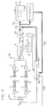
- FIG. 12 is a diagram of the signal system in the magnetic recording and reproducing apparatus of Embodiment 5. Portions having the same function as those of the magnetic recording and reproducing apparatuses of the above-mentioned embodiments are designated by the same reference numerals, and their description is omitted.
- signal lines of a thick line indicate digital signals which are expressed by plural bits, and those of a thin line indicate analog signals or digital signals which are expressed by one bit.
- the first and second recording heads 4 and 14 are mounted on the rotary cylinder 31 and alternatingly make contact with the magnetic tape 40 so as to conduct the recording operation thereon.
- a recording data 1 containing digital data to be recorded is supplied to a recording changeover switch 51 which is controlled by the recording head switch signal 29 synchronized with the rotary cylinder 31.
- the recording changeover switch 51 is connected to the upper terminal in FIG. 12.
- the signal which is to be recorded and is supplied through the recording changeover switch 51 is amplified by the first recording amplifier 2.
- the signal which is to be recorded and has been amplified is guided to the first recording head 4 on the rotary cylinder 31 through the first recording rotary-transformer 3 and then recorded onto the magnetic tape 40.
- the recording changeover switch 51 is connected to the lower terminal in FIG. 12. In this case, the signal which is to be recorded and is supplied through the recording changeover switch 51 is guided to the second recording head 14 on the rotary cylinder 31 through the second recording amplifier 12 and the second recording rotary-transformer 13 and then recorded onto the magnetic tape 40.
- the first and second reproducing heads 5 and 15 are mounted on the rotary cylinder 31 and alternatingly make contact with the magnetic tape 40 so as to conduct the reproducing operation thereon simultaneously with the above-mentioned recording operation.
- the reproducing changeover switch 61 shown in FIG. 12 is controlled by the reproducing head switch signal 30 which is synchronized with the rotary cylinder 31. During a period when the first reproducing head 5 makes contact with the magnetic tape 40, the reproducing changeover switch 61 is connected to the upper terminal in FIG. 12, and, during a period when the second reproducing head 15 makes contact with the magnetic tape 40, connected to the lower terminal in FIG. 12.
- a signal which has been reproduced by the first reproducing head 5 on the rotary cylinder 31 passes through the first reproducing rotary-transformer 6 and is then amplified by the first reproducing amplifier 7.
- the amplified signal is supplied to the equalizer 9 through the reproducing changeover switch 61.
- a signal which has been reproduced by the second reproducing head 15 on the rotary cylinder 31 passes through the second reproducing rotary-transformer 16 and is then amplified by the second reproducing amplifier 17.
- the amplified signal is supplied to the equalizer 9 through the reproducing changeover switch 61.
- the equalizer 9 the frequency characteristics of the system ranging from the recording operation to the reproducing operation are corrected, and the signal is equalized in order to enable digital codes to be discriminated.
- the equalized signal is supplied to the clock reproducing circuit 22 and an analog-to-digital converter 250.
- the clock reproducing circuit 22 generates the recovered clock signal 23 synchronized with the reproduced data, from the equalized signal.
- the A/D converter 250 samples the equalized signal by means of the recovered clock signal 23 and converts the signal into a digital signal.
- the signal which has been digitized in the A/D converter 250 is supplied to a subtractor 208 serving as the operating means.
- a signal 220 output from the subtractor 208 is supplied to a decoder 221 so that the data codes are subjected to discrimination, and then output as the reproduced data 24 from the discriminant circuit 221.
- the discriminant circuit 221 a circuit using a system in which the amplitude is compared with the threshold, or the known Viterbi decoding algorithm is employed may be used.
- the signals which are reproduced from the magnetic tape 40 by the first and second reproducing heads 5 and 15 are very weak.
- the current levels of the reproduced signals are lower by about 70 dB than the recording currents respectively flowing through the first and second recording heads 4 and 14.
- the recording and reproducing heads and the rotary-transformers are proximately disposed on the small rotary cylinder 31 of a diameter of about 20 mm. Consequently, crosstalk in which a recording signal leaks into a reproduced signal occurs in the magnetic recording and reproducing apparatus of Embodiment 5.
- the crosstalk from a recording signal to a reproduced signal occurs through many paths.
- such paths include those from the first or second recording head 4 or 14 to the first or second reproducing head 5 or 15, from the first or second recording rotary-transformer 3 or 13 to the first or second reproducing rotary-transformer 6 or 16, and from wirings between the recording rotary-transformers and the recording heads to wirings between the reproducing rotary-transformers and the reproducing heads.
- crosstalk components which finally leak into the output signal of the equalizer 9 through these many paths can be deemed as a signal which is obtained by convoluting a specific impulse response into the recording data 1. Therefore, crosstalk components can be artificially generated by convoluting the impulse response into the recording data 1.
- the magnetic recording and reproducing apparatus of Embodiment 5 is provided with an adaptive filter 225 serving as the adaptive filtering means.
- the adaptive filter 225 receives the recording data 1 and is controlled by an error signal 228.
- the impulse response of the adaptive filter 225 is controlled so as to have characteristics which approximate to the impulse response of crosstalk of the system ranging from the recording data 1 to the output of the equalizer 9.
- the output of the adaptive filter 225 is a pseudo crosstalk signal 226 which is artificially generated.
- the pseudo crosstalk signal 226 is expressed in the form of a digital signal.
- the pseudo crosstalk signal 226 is subtracted from the output signal of the A/D converter 250, thereby canceling crosstalk components leaking into the reproduced signal. As a result, crosstalk interference is largely reduced.
- an error detector 227 serving as the error detecting means, remaining crosstalk components are detected from the signal 220 which is the output of the subtractor 208 and fed back as the error signal 228 to the adaptive filter 225. Even when the condition of crosstalk is changed in accordance with the rotation phase of the rotary cylinder 31 or by changes in properties due to changes in temperature or with ages of the heads and electrical parts, therefore, the adaptive filter 225 is always controlled so as to have characteristics which approximate to crosstalk in the best manner.
- FIG. 13 is a block diagram showing the configuration of the error detector 227.
- a discriminant circuit 246 serving as discriminating means compares the amplitude of the signal 220 with a predetermined threshold level. The comparison result is supplied to a reference signal generator 247.
- the reference signal generator 247 outputs a reference signal 245 corresponding to the comparison result.
- a subtractor 249 serving as the operating means subtracts the reference signal 245 from the amplitude of the signal 220, and outputs the subtraction result as the error signal 228.
- FIG. 6 shows the eye pattern in the case where the signal 220 is considered as a continuous signal which has not yet been subjected to the sampling operation.
- the signal 220 is a signal which is obtained by digitizing the amplitude at the data discrimination time in FIG. 6.
- the eye pattern in the case where the signal 220 is considered as a continuous signal is shown.
- the signal 220 has an amplitude of A or -A at the data discrimination time. As shown in FIG. 6, however, the amplitude of the equalized signal 220 is actually caused not to always coincide with A or -A, by crosstalk from the recording signal or noises entering from the magnetic tape, the head system, and the like.
- the threshold level supplied to the discriminant circuit 246 shown in FIG. 13 is set to be an intermediate value between the amplitudes A and -A as shown in FIG. 6.
- the discriminant circuit 246 compares the amplitude of the threshold level with that of the signal 220 and outputs the comparison result.
- the reference signal generator 247 shown in FIG. 13 outputs either of the amplitudes A and -A. Specifically, if the amplitude of the signal 220 is larger than the threshold level, the circuit outputs the amplitude A as the reference signal 245, and, if the amplitude of the signal 220 is smaller than the threshold level, outputs the amplitude -A as the reference signal 245.
- the output of the subtractor 249 indicates the error between the amplitude of the signal 220 and the value which the signal should originally have. The output is used as the error signal 228.
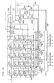
- FIG. 14 is a block diagram showing the configuration of the adaptive filter 225 of Embodiment 5.
- the adaptive filter 225 shown in FIG. 14 consists of a 4-tap FIR (Finite Impulse Response) type filter and adaptively operates so that the root mean square of the error signal 228 is always minimum.
- FIR Finite Impulse Response
- a recording data arrangement circuit 259 serving as the signal arranging means receives the recording data 1, a recording clock signal 258 synchronized with the recording data 1, and a recovered clock signal 23 synchronized with the reproduced data 24.
- Signals 255a, 255b, 255c, and 255d output from the recording data arrangement circuit 259 are obtained by making continuous 4-bit signals of the recording data 1 synchronize with the recovered clock signal 23.
- Signals 256a, 256b, 256c, and 256d output from the recording data arrangement circuit 259 are obtained by synchronizing the recording data 1 which is delayed by M bits from the signals 255a, 255b, 255c, and 255d, with the recovered clock signal 23.
- the signals 255a, 255b, 255c, and 255d at a certain time are r(i), r(i-1), r(i-2), and r(i-3), respectively, and the signals 256a, 256b, 256c, and 256d are r(i-M), r(i-M-1), r(i-M-2), and r(i-M-3), respectively.
- M 1.
- the configuration of the recording data arrangement circuit 259 will be mentioned later in detail.
- the reference numerals 265a, 265b, 265c, and 265d designate multipliers, respectively.
- the four multipliers 265a, 265b, 265c, and 265d constitute the first multiplying means group.
- a delayed error signal 252 which is obtained by latching the error signal 228 in a D-type flip-flop 254 by means of the recovered clock signal is supplied to one input of each of the multipliers 265a, 265b, 265c, and 265d.
- the signals 256a, 256b, 256c, and 256d are supplied to the other inputs of the multipliers 265a, 265b, 265c, and 265d, respectively.
- Each of the signals 256a, 256b, 256c, and 256d is a 1-bit signal indicative of "0" or "1.” The multiplication is conducted while assuming that the signals indicate "-1" or "1.”
- the reference numerals 268a, 268b, 268c, and 268d of FIG. 14 designate integrators serving as the integrating means.
- the integrators 268a, 268b, 268c, and 268d integrate the output signals of the multipliers 265a, 265b, 265c, and 265d and output the integration results, respectively.
- FIG. 15 is a block diagram showing the configuration of the integrator 268a.
- the integrator 268a consists of an adder 266 and a D-type flip-flop 267.
- the recovered clock signal 23 is supplied as a clock signal to the D-type flip-flop 267.
- the output signal of the adder 266 is delayed by one clock period and then fed back to the adder 266. According to this configuration, the signal supplied to the integrator 268a is accumulated at each clock pulse so that integration is conducted.
- the other integrators 268b, 268c, and 268d are configured in the strictly same manner as the integrator 268a shown in FIG. 15.
- reference numerals 257a, 257b, 257c, and 257d designate multipliers.
- the four multipliers 257a, 257b, 257c, and 257d constitute the second multiplying means group.
- the signals 255a, 255b, 255c, and 255d are supplied to inputs of one side of the multipliers 257a, 257b, 257c, and 257d, respectively, and the outputs of the integrators 268a, 268b, 268c, and 268d are supplied to the other inputs of the multipliers 257a, 257b, 257c, and 257d, respectively.
- Each of the signals 255a, 255b, 255c, and 255d is a 1-bit signal indicative of "0" or "1.” The multiplication is conducted while assuming that the signals indicate "-1" or "1.”
- the outputs of the multipliers 257a, 257b, 257c, and 257d are supplied to an adder 260 which serves as the operating means, and the total sum of the signals is supplied to a coefficient circuit 269.
- a predetermined coefficient a is multiplied with the output signal of the adder 260, and the multiplication result is output as the pseudo crosstalk signal 226.
- the error signal 228 is not directly supplied to the multipliers 265a, 265b, 265c, and 265d, and the delayed error signal 252 which is obtained by latching the error signal in the D-type flip-flop 254 by means of the recovered clock signal is supplied to the multipliers.
- This configuration is employed because the system for obtaining the error signal 228 is configured by a feedback loop as shown in FIGs. 12, 13, and 14 and a delay time due to the circuits in the feedback loop is absorbed by conducting the latching operation using the recovered clock signal.
- the signals 256a, 256b, 256c, and 256d output from the recording data arrangement circuit 259 are obtained by synchronizing the recording data which lags by M bits behind the signals 255a, 255b, 255c, and 255d, with the recovered clock signal 23.
- the value of M is equal to the delay time of the system ranging from the signal 255a to the delayed error signal 252 supplied to the multiplier 265a, through the pseudo crosstalk signal 226, the subtractor 208, the error detector 227, etc.
- each of these multipliers can be realized by a switch circuit which switches over the manners of the output operation, i.e., the output operation in which the other input is output as it is, or that in which the other input is inverted and then output, depending on the code of the 1-bit signal supplied to the one input.
- the signal component included in the signal 220 is indicated by s, crosstalk components leaking from the recording signal into the signal 220 by x, and the noise components from the tape and the like by n.
- the pseudo crosstalk signal 226 is indicated by y.
- the characteristics of the adaptive filter 225 are changed so that the average of the first term of the right side of expression (9) with respect to time i is minimum.
- the average of the second term of the right side is zero because the average of the noise components n is zero.
- the third term of the right side is independent from the pseudo crosstalk signal y.
- C j 0, 1, 2, and 3
- C j indicates the impulse response of the adaptive filter 225.
- the pseudo crosstalk signal y which is the output of the adaptive filter at time i is shown by the following expression where r i indicates the recording data at time i:
- the tap coefficient C j can be obtained by appropriately time-integrating a product of the delayed error signal 252 which is delayed from time i by M clock pulses and the recording data at time i-j-M.
- the adaptive filter 225 shown in FIG. 14 is a specific realization of the above. In the adaptive filter 225, therefore, its characteristics are adaptively changed so that the pseudo crosstalk signal 226 always optimally approximates to the crosstalk signal leaking into the reproduced signal in the meaning of minimizing the root mean square error.
- the pseudo crosstalk signal 226 is subtracted in the subtractor 208 from the signal 220, whereby crosstalk components leaking into the reproduced signal is canceled so as to be largely reduced.
- the recording data 1 is synchronized with the recording clock signal 258 of a period which is not varied or is stable.
- the time axes of the reproduced data 24 and the recovered clock signal 23 synchronized therewith are varied by rotation variation of the rotary cylinder 31 or the like. Therefore, the recording clock signal 258 and the recovered clock signal 23 are equal to each other in average frequency but the phase relationship between the clock signals are always varied.
- the recording data arrangement circuit 259 receives the recording data 1, the recording clock signal 258, and the recovered clock signal 23, outputs continuous 4-bit signals of the recording data 1 as the signals 255a, 255b, 255c, and 255d in synchronization with the recovered clock signal 23, and outputs the recording data 1 which is delayed from the signals 255a, 255b, 255c, and 255d by M bits, as the signals 256a, 256b, 256c, and 256d in synchronization with the recovered clock signal 23.
- the apparatus has also a function of rotating the arrangement of continuous 4-bit signals in accordance with the variation in phase relationship.
- FIG. 16 is a block diagram showing the configuration of the recording signal arrangement circuit 259.
- 278 designates a four-frequency divider which divides by four the frequency of the recording clock signal 258, and 279a, 279b, and 279c designate D-type flip-flops (hereinafter, such a flip-flop is abbreviated as "D-FF").
- D-FF D-type flip-flops
- the output of the four-frequency divider 278 is sequentially delayed by the D-FFs 279a, 279b, and 279c by means of the recording clock signal 258.
- the reference numerals 270a, 270b, 270c, and 270d designate D-FFs which use the recording clock signal 258 as a clock signal.
- the D-FFs 270a, 270b, 270c, and 270d sequentially delay the recording data 1.
- the reference numerals 274a, 274b, 274c, 274d, and 274e designate D-FFs which use the output of the four-frequency divider 278 as a clock signal.
- the D-FFs 274a, 274b, 274c, 274d, and 274e receive the recording data 1, and the output signals of the D-FFs 270a, 270b, 270c, and 270d, respectively.
- the reference numerals 273a, 273b, 273c, 273d, and 273e designate D-FFs which use the output of the D-FF 279a as a clock signal.
- the D-FFs 273a, 273b, 273c, 273d, and 273e receive the recording data 1, and the output signals of the D-FFs 270a, 270b, 270c, and 270d, respectively.
- the reference numerals 272a, 272b, 272c, 272d, and 272e designate D-FFs which use the output of the D-FF 279b as a clock signal.
- the D-FFs 272a, 272b, 272c, 272d, and 272e receive the recording data 1, and the output signals of the D-FFs 270a, 270b, 270c, and 270d, respectively.
- the reference numerals 271a, 271b, 271c, 271d, and 271e designate D-FFs which use the output of the D-FF 279c as a clock signal.
- the D-FFs 271a, 271b, 271c, 271d, and 271e receive the recording data 1, and the output signals of the D-FFs 270a, 270b, 270c, and 270d, respectively.
- 280a designates a 2-bit D-FF which uses the recovered clock signal 23 as a clock signal.
- the D-FF 280a functions as latching means for receiving the outputs of the four-frequency divider 278 and the D-FF 279a, latching the outputs by means of the recovered clock signal 23, and outputting signals 282a and 282b.
- the reference numeral 280b designates a 2-bit D-FF which uses the recovered clock signal 23 as a clock signal.
- the D-FF 280b functions as delaying means for delaying the signals 282a and 282b by means of the recovered clock signal 23, and outputting signals 283a and 283b.
- a state selector 281 outputs a state signal 284 at the timing of the recovered clock signal 23, in accordance with the signals 282a, 282b, 283a, and 283b.
- the state selector 281 functions as phase change detecting means as mentioned later.
- the unit consisting of the four-frequency divider 278, the D-FFs 279a, 280a, and 280b, and the state selector 281 constitutes a clock phase detector 285 serving as clock phase detecting means for detecting the phase relationship between the recording clock signal 258 and the recovered clock signal 23.
- a selector 276a receives the output signals of the D-FFs 271a, 272a, 273a, and 274a, and selectively outputs one of the four input signals in accordance with the signals 282a and 282b.
- a selector 276b receives the output signals of the D-FFs 271b, 272b, 273b, and 274b, and selectively outputs one of the four input signals in accordance with the signals 282a and 282b.
- a selector 276c receives the output signals of the D-FFs 271c, 272c, 273c, and 274c, and selectively outputs one of the four input signals in accordance with the signals 282a and 282b.
- a selector 276d receives the output signals of the D-FFs 271d, 272d, 273d, and 274d, and selectively outputs one of the four input signals in accordance with the signals 282a and 282b. Furthermore, a selector 276e receives the output signals of the D-FFs 271e, 272e, 273e, and 274e, and selectively outputs one of the four input signals in accordance with the signals 282a and 282b.
- 275a, 275b, 275c, 275d, and 275e designate D-FFs which uses the recovered clock signal 23 as a clock signal.
- the D-FFs 275a, 275b, 275c, 275d, and 275e receive the output signals of the selectors 276a, 276b, 276c, 276d, and 276e, respectively.
- a rearrangement circuit 277 receives the output signals of the D-FFs 275a, 275b, 275c, 275d, and 275e, rearranges the signals in accordance with the state signal 284, and outputs the signals 255a, 255b, 255c, and 255d, and 256a, 256b, 256c, and 256d.
- the rearrangement circuit 277 functions as rearranging means.
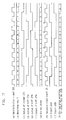
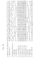
- FIGs. 17, 18, and 20 are timing charts showing signals of various portions of the recording signal arrangement circuit 259 of FIG. 16.
- FIG. 17 shows the recording clock signal 258,
- (b) shows the recording data 1 input in the sequence of A, B, C, ⁇
- (c) shows the signal which has been subjected to the frequency division in the four-frequency divider 278, and
- (d) shows the signal which has been subjected to the frequency division in the four-frequency divider 278, and
- (d) shows the signal which has been subjected to the frequency division in the four-frequency divider 278, and
- (e), and (f) respectively show the signals which are obtained by delaying the output signal of the four-frequency divider 278 in the D-FFs 279a, 279b, and 279c, respectively.
- the H level of a signal is indicated by "1" and the L level by "0.”
- the combination of the output signal of the four-frequency divider 278 and that of the D-FF 279a is indicated in the form of (the output signal of the four-frequency divider 278, the output signal of the D-FF 279a)
- the combination is repeated in the sequence of (0, 0), (1, 0), (1, 1), (0, 1), (0, 0) ..., or constitutes a Gray code in which only 1 bit of 2 bits has a different value in adjacent zones.
- the four-frequency divider 278 and the D-FF 279a function as frequency dividing means for converting the divided phase into a Gray code and then outputting the Gray code.
- the states of (0, 0), (1, 0), (1, 1), (0, 1) are indicated by the divided phases of "0,” “1,” "2,” and "3,” respectively.
- the period of the recovered clock signal 23 is varied by rotation variation of the rotary cylinder or the like.
- the phase relationship between the rising timing of the recovered clock signal 23 and the recording clock signal 258 is changed at times tl and t3. Therefore, the signals 282a and 282b which are obtained by latching the output signals of the four-frequency divider 278 and the D-FF 279a by means of the recovered clock signal 23 are signals shown in (i) and (j) of FIG. 17, respectively.
- the divided phase of the signals 282a and 282b which is indicated in the form of a Gray code is not continuously changed in the sequence of "0,” “1,” “2,” 3,” “0,” “1,” ⁇ , but is discontinuous at times t1 and t3.
- the divided phase is recognized on the basis of the signals 282a and 282b which are obtained by latching the output signals of the four-frequency divider 278 and the D-FF 279a by means of the recovered clock signal 23.
- these 2 bits are expressed as a result of converting the divided phase into a Gray code.
- the reason why a Gray code is used is that, even when the 2 bits are delicately shifted in timing from each other, the phase is prevented from being erroneously detected because only 1 bit of the 2 bits has a different value in adjacent zones.
- the selector 276a in FIG. 16 selectively outputs the output of the D-FF 272a.
- the selected signal is latched in the D-FF 275a at the rising timing of the recovered clock signal 23.
- the rising timing of the output of the D-FF 279b shown in (e) of FIG. 17 leads by IT to 2T the timing when the divided phase indicated by the signals 282a and 282b shown in (k) of FIG.
- the selector 276a selectively outputs the output of the D-FF 271a, when the phase is “2,” selectively outputs the output of the D-FF 274a, and, when the phase is "3,” selectively outputs the output of the D-FF 273a.
- the recording data can be surely synchronized with the recovered clock signal 23 in the D-FF 275a irrespective of the phase relationship between the recording clock signal 258 and the recovered clock signal 23 in which the period is varied.
- selectors 276b to 276e operate in the same manner as the selector 276a.
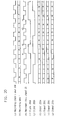
- the D-FFs 275a to 275e output the 5-bit recording data which is always continuous at any time in synchronization with the recovered clock signal 23, as shown in (l) to (p) of FIG. 18.
- the state selector 281 functions as phase change detecting means
- the rearrangement circuit 277 functions as rearranging means, thereby conducting processing so that, even when the phase relationship between the recording clock signal 258 and the recovered clock signal 23 is changed, a large error is not produced in the pseudo crosstalk signal 226 of FIG. 14.
- (q) and (r) show the signals 283a and 283b, respectively.
- the signal 282a shown in (i) of FIG. 18 is compared with the signal 283a shown in (q) or the signal 282b shown in (j) of FIG. 18 is compared with the signal 283b shown in (r)
- both the comparison results indicate difference in the time period between times tl and t2
- equality in the time period between times t3 and t4 In the other time periods, only one of the two comparisons results indicate difference.
- the change of the phase relationship between the recording clock signal 258 and the recovered clock signal 23 can be known from the result of comparison between the signals 282a and 283a and that of comparison between the signals 282b and 283b.
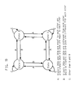
- FIG. 19 is a state transition diagram illustrating the relationships among the four states “0,” “1,” “2,” and “3” of the state selector 281.
- an event in which the signals 282a and 283a are equal to each other and also the signals 282b and 283b are equal to each other is indicated by A
- an event in which the signals 282a and 283a are different from each other and also the signals 282b and 283b are different from each other is indicated by B
- events other than the events A and B are indicated by C.
- an event in which both the comparison results indicate equality is indicated by A
- an event in which both the comparison results indicate difference is indicated by B
- an event in which only one of the comparison results indicate difference is indicated by C.
- the state held by the state selector 281 changes as shown in FIG. 19. In (s) of FIG. 18, the manner of changing the state indicated by the state signal 284 is shown.
- the rearrangement circuit 277 shown in FIG. 16 outputs the output signals of the D-FFs 275a, 275b, 275c, and 275d as the signals 255a, 255b, 255c, and 255d, and those of the D-FFs 275b, 275c, 275d, and 275e as the signals 256a, 256b, 256c, and 256d, respectively.
- the circuit When the state signal 284 indicates state "1," the circuit outputs the output signals of the D-FFs 275b, 275c, 275d, and 275e as the signals 255a, 255b, 255c, and 255d, and those of the D-FFs 275c, 275d, 275e, and 275b as the signals 256a, 256b, 256c, and 256d, respectively.
- the circuit When the state signal 284 indicates state "2," the circuit outputs the output signals of the D-FFs 275c, 275d, 275a, and 275b as the signals 255a, 255b, 255c, and 255d, and those of the D-FFs 275d, 275e, 275b, and 275c as the signals 256a, 256b, 256c, and 256d, respectively.
- the circuit When the state signal 284 indicates state "3," the circuit outputs the output signals of the D-FFs 275d, 275a, 275b, and 275c as the signals 255a, 255b, 255c, and 255d, and those of the D-FFs 275e, 275b, 275c, and 275d as the signals 256a, 256b, 256c, and 256d, respectively.
- the value of the center of the impulse responses for continuous 4 data is larger and the value becomes smaller as moving toward the ends. Even when an error due to discontinuity occurs in the impulse responses for the ends, therefore, an error occurring in the pseudo crosstalk signal 226 is small in degree as far as the continuity of the other portions including the center is maintained.
- M 1
- the recording signal arrangement circuit has also a function that the signal arrangement is changed by rotating the arrangement of continuous 4 bit signals in accordance with the change in phase relationship, so that the pseudo crosstalk signal 226 is stably obtained even when the phase relationship between the recording clock signal 258 and the recovered clock signal 23 is changed.
- the signal arrangement is changed so that, when the recording clock signal is n at time m+1 of the recovered clock signal, r[n-h-i] with q[mod(i+j+1)] is output, when the recording clock signal is n+1 at time m+1 of the recovered clock signal, r[n-h-i+1] with q[mod(i+j)] is output, and, when the recording clock signal is n+2 at time m+1 of the recovered clock signal, r[n-h-i+2] with q[mod(i+j-1)] is output.
- the integer h indicates the delayed time due to the process of synchronizing the recording data 1 with the recovered clock signal 23.
- Embodiment 5 of the present invention although the small rotary cylinder in which separation between the recording and reproduced signals is hardly conducted by electromagnetic means is used, simultaneous reproduction is enabled while crosstalk components are largely cancelled reduced by subtracting the pseudo crosstalk component which is artificially generated, from the reproduced signal, thereby reducing crosstalk interference applied to the reproduced signal.
- the pseudo crosstalk signal is always adaptively generated. Even when the condition of crosstalk is changed in accordance with the rotation phase of the rotary cylinder or by changes in properties due to changes in temperature or with ages of the heads and electrical parts, therefore, simultaneous reproduction can be always conducted under the best conditions. Even when the phase relationship between recording data and reproduced data is varied by rotation variation of the rotary cylinder or the like, simultaneous reproduction can be conducted without being affected by such variation.
- M has a larger value.
- the recording data arrangement circuit 259 is configured so that the signals 256a, 256b, 256c, and 256d output from the recording data arrangement circuit 259 cause the recording data which lag by M bits behind the signals 255a, 255b, 255c, and 255d to be output with being synchronized with the recovered clock signal 23.
- Embodiment 5 is an example in which the adaptive filtering means is configured by a 4-tap FIR type filter.
- the present invention is not restricted to this.
- the number of taps is further increased, for example, it is possible to more correctly approximate crosstalk components, with the result that the effect of reducing crosstalk can be further enhanced.
- the adaptive filtering means (225), the operating means (208), the error detecting means (227), etc. are executed so as to conduct digital processing.
- such means may be executed so as to conduct analog processing.
- the same effects as those of the embodiment can be attained.
- FIG. 21 is a diagram showing the signal system in the magnetic recording and reproducing apparatus of Embodiment 6. Portions having the same function as those of the magnetic recording and reproducing apparatuses of the above-mentioned Embodiment 5 are designated by the same reference numerals, and their description is omitted.
- signal lines of a thick line indicate digital signals which are expressed by plural bits, and those of a thin line indicate analog signals or digital signals which are expressed by one bit.
- the magnetic recording and reproducing apparatus of Embodiment 6 comprises a pair of recording heads and a pair of reproducing heads which are mounted on a small rotary cylinder as shown in FIGs. 1 and 2, and digital data are recorded onto and reproduced from a magnetic tape which is slantly wound on the rotary cylinder and travels thereon.
- the apparatus of Embodiment 6 is different from Embodiment 5 only in the signal system. In the following, description on the signal system only will be done.
- the embodiment is different from Embodiment 5 only in that a delay circuit 253 which delays the recording data 1 by 4 periods of the recording clock signal and the signal which has been delayed by the delay circuit 253 is supplied to the recording changeover switch 51 so as to be used as a recording signal.
- Embodiment 5 as seen from the timing chart of FIG. 20, there occurs a delay in the operation of outputting the recording data 1 of (b) as the signal 255a of (t).
- the recording data 1 of (b) is "P,” for example, "L” is output as the signal 255a of (t) or a delay corresponding to 4 bits is done. Consequently, the recording data 1 of the 4 bits do not exert influence on the pseudo crosstalk signal 226 output from the adaptive filter 225.
- Embodiment 6 shown in FIG. 21 therefore, a signal which is obtained by delaying the recording data 1 by 4 periods of the recording clock signal by the delay circuit 253 is supplied to the recording heads.
- This causes data which have not yet been sent to the recording heads to be previously supplied to the adaptive filter 225. Therefore, the recording data 1 exerts influence on the pseudo crosstalk signal 226 output from the adaptive filter 225 while the delay time due to the processing does not affect the pseudo crosstalk signal 226.
- the present invention is not restricted to this.
- the present invention may be applied to a tape recording apparatus using a fixed head or a recording and reproducing apparatus in which data are recorded onto a rotary medium such as a hard disk.
- the magnetic recording and reproducing apparatus of above embodiments are examples in which the heads are mounted on the rotary cylinder.
- the present invention is not restricted to those examples.
- the present invention may be applied to a tape recording apparatus using a fixed head or a recording and reproducing apparatus in which data are recorded onto a rotary medium such as a hard disk.
Landscapes
- Engineering & Computer Science (AREA)
- Signal Processing (AREA)
- Digital Magnetic Recording (AREA)
- Signal Processing For Digital Recording And Reproducing (AREA)
- Signal Processing Not Specific To The Method Of Recording And Reproducing (AREA)
Claims (11)
- Aufzeichnungs- und Wiedergabegerät, aufweisend:dadurch gekennzeichnet, daßzumindest einen Aufzeichnungskopf (4, 14, 72a, 72b, 73a, 73b), der ein Aufzeichnungssignal auf einem magnetischen Aufzeichnungsmedium aufzeichnet;zumindest einen Aufzeichnungskopf (5, 15, 74a, 74b, 75a, 75b), der ein aufgezeichnetes Signal wiedergibt;zumindest einen Filter (25, 112a, 112b, 113a, 113b, 225) zum Empfangen des Aufzeichnungssignals und Ausgeben eines Pseudo-Übersprechsignals, bei dem es sich um ein Signal handelt, das Übersprechkomponenten aufweist, die künstlich erzeugt sind;eine Betriebseinrichtung (8, 101a, 101b, 102a, 102b) zum Subtrahieren des Pseudo-Übersprechsignals des Filters von dem durch den Aufzeichnungskopf wiedergegebenen Signal;der Filter ein adaptiver Filter ist;und daß zusätzlich eine Fehlerermittlungseinrichtung (21, 27, 104a, 104b, 114a, 114b, 227) zum Ermitteln eines Fehlersignals in Übereinstimmung mit einem Ausgangssignal der Betriebseinrichtung und zum Rückkoppeln des Fehlersignals zu dem adaptiven Filter vorgesehen ist.
- Aufzeichnungs- und Wiedergabegerät nach Anspruch 1, aufweisend:eine Anzahl N oder N Sätze von Aufzeichnungsköpfen (72a, 72b, 73a, 73b), die Aufzeichnungssignale von N Systemen (N ist eine ganze Zahl nicht kleiner als 2) auf einem magnetischen Aufzeichnungsmedium aufzeichnen; undeine Anzahl N oder N Sätze von Wiedergabeköpfen (74a, 74b, 75a, 75b), die ein aufgezeichnetes Signal wiedergeben, wobei die Vorrichtung außerdem für jeden der N oder N Sätze von Wiedergabeköpfen aufweist:eine Anzahl N von adaptiven Filtern (112a, 112b, 113a, 113b), die jeweils die Aufzeichnungssignale von N Systemen empfangen;eine Betriebseinrichtung (101a, 101b, 102a, 102b) zum Subtrahieren von Ausgangssignalen der N adaptiven Filter von einem Signal, das in Übereinstimmung mit einem oder einem Satz von Wiedergabeköpfen wiedergegeben wird.
- Aufzeichnungs- und Wiedergabegerät nach Anspruch 1 oder 2, wobei die Fehlerermittlungseinrichtung (21, 27, 104a, 104b, 114a, 114b) aufweist:einen Diskriminator (21, 104a, 104b) zum Diskriminieren von Codes des wiedergegebenen Signals; undeine Betriebseinrichtung (27, 114a, 114b) zum Ausgeben einer Differenz zwischen einem Bezugswert in Übereinstimmung mit einem Diskriminierungsergebnis des Diskriminators und dem wiedergegebenen Signal als Fehlersignal.
- Aufzeichnungs- und Wiedergabegerät nach Anspruch 1 oder 2, wobei der adaptive Filter (25) aufweist:mehrere Verzögerungsmittel (55, 56) zum Verzögern des Aufzeichnungssignals um eine vorbestimmte Zeitdauer;ein erstes Multipliziermittel (65, 66, 67), aufweisend mehrere Multiplizierer, welche jeweils Ausgangssignale der mehreren Verzögerungseinrichtungen als ein Eingangssignal empfangen, und die das Fehlersignal als anderes Eingangssignal empfangen;mehrere Integriermittel (68, 69, 70) zum jeweiligen Integrieren von Ausgangssignalen der mehreren Multiplizierer des ersten Multipliziermittels;zweite Multipliziermittel (57, 58, 59), aufweisend mehrere Multiplizierer, welche jeweils Ausgangssignale der mehreren Verzögerungsmittel als ein Eingangssignal empfangen, und welche jeweils Ausgangssignale der mehreren Integriermittel als anderes Eingangssignal empfangen; undeine Betriebseinrichtung (60) zum Ausgeben einer Gesamtsumme von Ausgangssignalen der Multiplizierer des zweiten Multipliziermittels als Ausgangssignal des adaptiven Filters.
- Aufzeichnungs- und Wiedergabegerät nach Anspruch 1, wobei ein Wiedergabevorgang simultan mit einem Aufzeichnungsvorgang durchgeführt wird, aufweisend:
ein rückgewonnenes Taktsignal-Erzeugungsmittel (22) zum Erzeugen eines rückgewonnenen Signals von dem wiedergegebenen Signal, wobei das rückgewonnene Signal mit wiedergegebenen Daten synchronisiert ist,
wobei der adaptive Filter (225) aufweist:ein Signalanordnungsmittel (259) zum Ausgeben einer Anzahl K von kontinuierlichen Aufzeichnungsdaten (K ist eine natürliche Zahl) von einem Aufzeichnungsdatenstrom als erste Datengruppe synchron zu dem rückgewonnenen Taktsignal, undzum Ausgeben einer Anzahl K von weiteren kontinuierlichen Aufzeichnungsdaten von dem Aufzeichnungsdatenstrom als zweite Datengruppe synchron zu dem rückgewonnenen Taktsignal;eine erste Gruppe von Multipliziermitteln (265a, 265b, 265c, 265d), bestehend aus einer Anzahl K von Multipliziermitteln, wobei die erste Gruppe von Multipliziermitteln K Daten der zweiten Datengruppe als ein Eingangssignal empfangen und das Fehlersignal als weiteres Eingangssignal empfangen;eine Anzahl K von Integriermitteln (268a, 268b, 268c, 268d) zum Integrieren von jedem der Ausgangssignale der K Multipliziermittel der ersten Gruppe von Multipliziermitteln;eine zweite Gruppe von Multipliziermitteln (257a, 257b, 257c, 257d), bestehend aus einer Anzahl K von Multipliziermitteln, wobei die zweite Gruppe von Multipliziermitteln K Daten der ersten Datengruppe als ein Eingangssignal empfangen und Ausgangssignale der K Integriermittel als weiteres Eingangssignal; undeine Betriebseinrichtung (260, 269) zum Berechnen einer Gesamtsumme von Ausgangssignalen der K Multipliziermittel der zweiten Gruppe von Multipliziermitteln und zum Ausgeben der Gesamtsumme als Ausgangssignal des adaptiven Filters. - Aufzeichnungs- und Wiedergabegerät nach Anspruch 5, wobei das Fehlerermittlungsmittel (227) aufweist: einen Diskriminator (246) zum Diskriminieren von Codes von dem wiedergegebenen Signal; und eine Betriebseinrichtung (249) zum Ausgeben einer Differenz zwischen einem Bezugswert in Übereinstimmung mit einem Diskriminierungsergebnis des Diskriminators und des wiedergegebenen Signals als Fehlersignal (228).
- Aufzeichnungs- und Wiedergabegerät nach Anspruch 6, wobei das Signalanordnungsmittel (259) aufweist: ein Taktphasen-Ermittlungsmittel (285) zum Ermitteln einer Änderung einer Phasenbeziehung zwischen dem rückgewonnenen Taktsignal und einem Aufzeichnungstaktsignal synchron zu den Aufzeichnungsdaten; und ein Wiederanordnungsmittel (277) zum Ändern einer Signalanordnung der K aufgezeichneten Daten von jeder der ersten und zweiten Datengruppen in Übereinstimmung mit einem Ermittlungsergebnis des Taktphasen-Ermittlungsmittels.
- Aufzeichnungs- und Wiedergabegerät nach Anspruch 6, wobei die Vorrichtung außerdem ein Verzögerungsmittel (253) zum Zuführen der Aufzeichnungsdaten zu dem Aufzeichnungskopf umfaßt, wobei die Aufzeichnungsdaten um eine vorbestimmte Zeitdauer verzögert werden.
- Aufzeichnungs- und Wiedergabegerät nach Anspruch 7, wobei das Taktphasen-Ermittlungsmittel (285) aufweist: ein Frequenzteilungsmittel (278) zum Unterteilen einer Frequenz des Aufzeichnungstaktsignals und zum Ausgeben einer geteilten Phase; ein Verriegelungsmittel (280a) zum Abtasten eines Ausgangssignals des Frequenzteilungsmittels mittels des rückgewonnenen Taktsignals; ein Verzögerungsmittel (280b) zum Verzögern eines Ausgangssignals des Verriegelungsmittels um eine Periode des rückgewonnenen Taktsignals; und ein Phasenänderungs-Ermittlungsmittel (281) zum Ermitteln einer Änderung einer Phasenbeziehung zwischen dem Aufzeichnungstaktsignal und dem rückgewonnenen Taktsignal von dem Ausgangssignal des Verriegelungsmittels und einem Ausgangssignal des Verzögerungsmittels.
- Aufzeichnungs- und Wiedergabegerät nach Anspruch 7, wobei das Wiederanordnungsmittel (277) eine Signalanordnung derart ändert, daß dann, wenn die K Datenausgangssignale der ersten Datengruppe des Signalanordnungsmittels wiedergegeben sind durch (q[0], q[1], ..., q[K-1]}, die Aufzeichnungsdaten zum Zeitpunkt n des Aufzeichnungstaktsignals wiedergegeben sind durch r[n], und wobei angenommen wird, daß dann, wenn r[n-h-i] mit q[mod(i+j)] (i = 0, 1, ..., K-1, j und h sind ganze Zahlen, und mod(A) bezeichnet einen Rest in dem Fall, daß eine ganze Zahl A durch K geteilt ist) ausgegeben wird, r[n-h-i] mit q[mod(i+j+1)] ausgegeben wird, wenn der Zeitpunkt des Aufzeichnungstaktsignals zum Zeitpunkt m+1 des rückgewonnenen Taktsignals n ist, r[n-h-i+1] mit q[mod(i+j)] ausgegeben wird, wenn der Zeitpunkt des Aufzeichnungssignals zum Zeitpunkt m+1 des rückgewonnenen Taktsignals n+1 ist, und r[n-h-i+2] mit q[mod(i+j-1)] ausgegeben wird, wenn der Zeitpunkt des Aufzeichnungstaktsignals zum Zeitpunkt m+1 des rückgewonnenen Taktsignals n+2 ist.
- Aufzeichnungs- und Wiedergabegerät nach Anspruch 9, wobei das Frequenzteilungsmittel (278) die durch Teilen der Frequenz des Aufzeichnungstaktsignals gewonnene geteilte Phase in einen Gray-Code wandelt und daraufhin die geteilte Phase ausgibt.
Applications Claiming Priority (6)
| Application Number | Priority Date | Filing Date | Title |
|---|---|---|---|
| JP51767/96 | 1996-03-08 | ||
| JP5176796 | 1996-03-08 | ||
| JP05176796A JP3529535B2 (ja) | 1996-03-08 | 1996-03-08 | 記録再生装置 |
| JP334246/96 | 1996-12-13 | ||
| JP33424696 | 1996-12-13 | ||
| JP8334246A JP3059394B2 (ja) | 1996-12-13 | 1996-12-13 | 記録再生装置 |
Publications (3)
| Publication Number | Publication Date |
|---|---|
| EP0794529A2 EP0794529A2 (de) | 1997-09-10 |
| EP0794529A3 EP0794529A3 (de) | 1998-04-01 |
| EP0794529B1 true EP0794529B1 (de) | 2001-01-17 |
Family
ID=26392328
Family Applications (1)
| Application Number | Title | Priority Date | Filing Date |
|---|---|---|---|
| EP97103525A Expired - Lifetime EP0794529B1 (de) | 1996-03-08 | 1997-03-04 | Aufnahme- und Wiedergabegerät |
Country Status (3)
| Country | Link |
|---|---|
| US (1) | US5991108A (de) |
| EP (1) | EP0794529B1 (de) |
| DE (1) | DE69703904T2 (de) |
Families Citing this family (4)
| Publication number | Priority date | Publication date | Assignee | Title |
|---|---|---|---|---|
| JP2003141701A (ja) * | 2001-11-06 | 2003-05-16 | Sony Corp | 記録再生装置 |
| JP3693014B2 (ja) * | 2001-12-26 | 2005-09-07 | ソニー株式会社 | 記録再生装置及びクロストークキャンセル方法 |
| US9626999B1 (en) * | 2015-12-18 | 2017-04-18 | Avago Technologies General Ip (Singapore) Pte. Ltd. | Systems and methods for real time ITI compensation in a multi-dimensional equalizer |
| JP2022025918A (ja) * | 2020-07-30 | 2022-02-10 | 株式会社東芝 | 磁気ディスク装置 |
Family Cites Families (8)
| Publication number | Priority date | Publication date | Assignee | Title |
|---|---|---|---|---|
| US4331992A (en) * | 1979-02-23 | 1982-05-25 | Robert Bosch Gmbh | Method and apparatus for eliminating crosstalk in magnetic tape recorders |
| NL8203618A (nl) * | 1982-09-20 | 1984-04-16 | Philips Nv | Inrichting voor het uitlezen van een registratiedrager. |
| JPS6052902A (ja) * | 1983-09-01 | 1985-03-26 | Matsushita Electric Ind Co Ltd | 磁気記録再生装置 |
| JPS61142502A (ja) * | 1984-12-13 | 1986-06-30 | Matsushita Electric Ind Co Ltd | 磁気テ−プのデ−タ再生装置 |
| JPH02198002A (ja) * | 1989-01-27 | 1990-08-06 | Hitachi Ltd | 回転磁気ヘッド装置 |
| JPH0334103A (ja) * | 1989-06-29 | 1991-02-14 | Sony Corp | 回転ヘッド装置 |
| JPH03232101A (ja) * | 1990-02-07 | 1991-10-16 | Hitachi Ltd | 回転ドラム装置 |
| JPH03286403A (ja) * | 1990-03-31 | 1991-12-17 | Toshiba Corp | 回転ヘッド型記録再生装置 |
-
1997
- 1997-02-24 US US08/804,592 patent/US5991108A/en not_active Expired - Fee Related
- 1997-03-04 DE DE69703904T patent/DE69703904T2/de not_active Expired - Fee Related
- 1997-03-04 EP EP97103525A patent/EP0794529B1/de not_active Expired - Lifetime
Also Published As
| Publication number | Publication date |
|---|---|
| US5991108A (en) | 1999-11-23 |
| EP0794529A2 (de) | 1997-09-10 |
| EP0794529A3 (de) | 1998-04-01 |
| DE69703904D1 (de) | 2001-02-22 |
| DE69703904T2 (de) | 2001-05-10 |
Similar Documents
| Publication | Publication Date | Title |
|---|---|---|
| CA1134941A (en) | Recording digital signals | |
| US7379452B2 (en) | Synchronous read channel | |
| EP0663117B1 (de) | Taktrückgewinnungsschaltung für synchrone wellenformabtastung | |
| US5592340A (en) | Communication channel with adaptive analog transversal equalizer | |
| US5502711A (en) | Dual digital phase locked loop clock channel for optical recording | |
| US5426539A (en) | Multiple gap read/write head for data storage devices | |
| CA1214264A (en) | Digital data detecting apparatus | |
| WO1994018773A1 (en) | Gain control circuit for synchronous waveform sampling | |
| WO1980000760A1 (en) | Error recognition and correction of digital information | |
| US5557482A (en) | Multipath channel apparatus and method for data storage devices and communications systems wherein a data path is selected based on errors | |
| US5625632A (en) | Magnetic disk drive including a data discrimination apparatus capable of correcting signal waveform distortion due to intersymbol interference | |
| US5455813A (en) | Digital signal reproducing apparatus | |
| KR100445391B1 (ko) | 통신채널에대한시간영역필터 | |
| JP3428376B2 (ja) | 自動等化システム | |
| EP0794529B1 (de) | Aufnahme- und Wiedergabegerät | |
| GB2118403A (en) | Digital signal demodulator circuit | |
| US4371900A (en) | Equalization of DC null in reproducing a high density recording | |
| KR100243218B1 (ko) | 데이터 복호장치와 그 방법 | |
| US5337198A (en) | Digital magnetic writing and reading apparatus | |
| US6654413B2 (en) | Phase synchronization method for extended partial response, and phase synchronization circuit and read channel circuit using this method | |
| US6304400B1 (en) | Signal dropout compensation | |
| JP3059394B2 (ja) | 記録再生装置 | |
| EP0583818B1 (de) | Empfangsanordnung zum Empfang eines digitalen Signals von einem Übertragungsmedium mit variablen Entzerrungsmitteln | |
| JP3529535B2 (ja) | 記録再生装置 | |
| JPH0636208A (ja) | データ検出装置 |
Legal Events
| Date | Code | Title | Description |
|---|---|---|---|
| PUAI | Public reference made under article 153(3) epc to a published international application that has entered the european phase |
Free format text: ORIGINAL CODE: 0009012 |
|
| 17P | Request for examination filed |
Effective date: 19970304 |
|
| AK | Designated contracting states |
Kind code of ref document: A2 Designated state(s): DE FR GB NL |
|
| PUAL | Search report despatched |
Free format text: ORIGINAL CODE: 0009013 |
|
| AK | Designated contracting states |
Kind code of ref document: A3 Designated state(s): DE FR GB NL |
|
| 17Q | First examination report despatched |
Effective date: 19981130 |
|
| GRAG | Despatch of communication of intention to grant |
Free format text: ORIGINAL CODE: EPIDOS AGRA |
|
| 17Q | First examination report despatched |
Effective date: 19981130 |
|
| GRAG | Despatch of communication of intention to grant |
Free format text: ORIGINAL CODE: EPIDOS AGRA |
|
| GRAG | Despatch of communication of intention to grant |
Free format text: ORIGINAL CODE: EPIDOS AGRA |
|
| GRAH | Despatch of communication of intention to grant a patent |
Free format text: ORIGINAL CODE: EPIDOS IGRA |
|
| GRAH | Despatch of communication of intention to grant a patent |
Free format text: ORIGINAL CODE: EPIDOS IGRA |
|
| GRAH | Despatch of communication of intention to grant a patent |
Free format text: ORIGINAL CODE: EPIDOS IGRA |
|
| GRAA | (expected) grant |
Free format text: ORIGINAL CODE: 0009210 |
|
| AK | Designated contracting states |
Kind code of ref document: B1 Designated state(s): DE FR GB NL |
|
| REF | Corresponds to: |
Ref document number: 69703904 Country of ref document: DE Date of ref document: 20010222 |
|
| ET | Fr: translation filed | ||
| PLBE | No opposition filed within time limit |
Free format text: ORIGINAL CODE: 0009261 |
|
| STAA | Information on the status of an ep patent application or granted ep patent |
Free format text: STATUS: NO OPPOSITION FILED WITHIN TIME LIMIT |
|
| REG | Reference to a national code |
Ref country code: GB Ref legal event code: IF02 |
|
| 26N | No opposition filed | ||
| PGFP | Annual fee paid to national office [announced via postgrant information from national office to epo] |
Ref country code: NL Payment date: 20090315 Year of fee payment: 13 |
|
| PGFP | Annual fee paid to national office [announced via postgrant information from national office to epo] |
Ref country code: GB Payment date: 20090304 Year of fee payment: 13 |
|
| PGFP | Annual fee paid to national office [announced via postgrant information from national office to epo] |
Ref country code: DE Payment date: 20090226 Year of fee payment: 13 |
|
| PGFP | Annual fee paid to national office [announced via postgrant information from national office to epo] |
Ref country code: FR Payment date: 20090316 Year of fee payment: 13 |
|
| REG | Reference to a national code |
Ref country code: NL Ref legal event code: V1 Effective date: 20101001 |
|
| GBPC | Gb: european patent ceased through non-payment of renewal fee |
Effective date: 20100304 |
|
| REG | Reference to a national code |
Ref country code: FR Ref legal event code: ST Effective date: 20101130 |
|
| PG25 | Lapsed in a contracting state [announced via postgrant information from national office to epo] |
Ref country code: NL Free format text: LAPSE BECAUSE OF NON-PAYMENT OF DUE FEES Effective date: 20101001 Ref country code: FR Free format text: LAPSE BECAUSE OF NON-PAYMENT OF DUE FEES Effective date: 20100331 |
|
| PG25 | Lapsed in a contracting state [announced via postgrant information from national office to epo] |
Ref country code: DE Free format text: LAPSE BECAUSE OF NON-PAYMENT OF DUE FEES Effective date: 20101001 |
|
| PG25 | Lapsed in a contracting state [announced via postgrant information from national office to epo] |
Ref country code: GB Free format text: LAPSE BECAUSE OF NON-PAYMENT OF DUE FEES Effective date: 20100304 |