EP0793268A2 - Verfahren zum Füllen von Löchern in einer Halbleiteranordnung - Google Patents
Verfahren zum Füllen von Löchern in einer Halbleiteranordnung Download PDFInfo
- Publication number
- EP0793268A2 EP0793268A2 EP96108163A EP96108163A EP0793268A2 EP 0793268 A2 EP0793268 A2 EP 0793268A2 EP 96108163 A EP96108163 A EP 96108163A EP 96108163 A EP96108163 A EP 96108163A EP 0793268 A2 EP0793268 A2 EP 0793268A2
- Authority
- EP
- European Patent Office
- Prior art keywords
- cavity
- process according
- depositing
- semiconductor body
- providing
- Prior art date
- Legal status (The legal status is an assumption and is not a legal conclusion. Google has not performed a legal analysis and makes no representation as to the accuracy of the status listed.)
- Withdrawn
Links
Images


Classifications
-
- H—ELECTRICITY
- H01—ELECTRIC ELEMENTS
- H01L—SEMICONDUCTOR DEVICES NOT COVERED BY CLASS H10
- H01L21/00—Processes or apparatus adapted for the manufacture or treatment of semiconductor or solid state devices or of parts thereof
- H01L21/70—Manufacture or treatment of devices consisting of a plurality of solid state components formed in or on a common substrate or of parts thereof; Manufacture of integrated circuit devices or of parts thereof
- H01L21/71—Manufacture of specific parts of devices defined in group H01L21/70
- H01L21/768—Applying interconnections to be used for carrying current between separate components within a device comprising conductors and dielectrics
- H01L21/76838—Applying interconnections to be used for carrying current between separate components within a device comprising conductors and dielectrics characterised by the formation and the after-treatment of the conductors
- H01L21/76841—Barrier, adhesion or liner layers
- H01L21/76853—Barrier, adhesion or liner layers characterized by particular after-treatment steps
- H01L21/76855—After-treatment introducing at least one additional element into the layer
- H01L21/76858—After-treatment introducing at least one additional element into the layer by diffusing alloying elements
-
- H—ELECTRICITY
- H01—ELECTRIC ELEMENTS
- H01L—SEMICONDUCTOR DEVICES NOT COVERED BY CLASS H10
- H01L21/00—Processes or apparatus adapted for the manufacture or treatment of semiconductor or solid state devices or of parts thereof
- H01L21/70—Manufacture or treatment of devices consisting of a plurality of solid state components formed in or on a common substrate or of parts thereof; Manufacture of integrated circuit devices or of parts thereof
- H01L21/71—Manufacture of specific parts of devices defined in group H01L21/70
- H01L21/768—Applying interconnections to be used for carrying current between separate components within a device comprising conductors and dielectrics
- H01L21/76838—Applying interconnections to be used for carrying current between separate components within a device comprising conductors and dielectrics characterised by the formation and the after-treatment of the conductors
- H01L21/76841—Barrier, adhesion or liner layers
- H01L21/76843—Barrier, adhesion or liner layers formed in openings in a dielectric
-
- H—ELECTRICITY
- H01—ELECTRIC ELEMENTS
- H01L—SEMICONDUCTOR DEVICES NOT COVERED BY CLASS H10
- H01L21/00—Processes or apparatus adapted for the manufacture or treatment of semiconductor or solid state devices or of parts thereof
- H01L21/70—Manufacture or treatment of devices consisting of a plurality of solid state components formed in or on a common substrate or of parts thereof; Manufacture of integrated circuit devices or of parts thereof
- H01L21/71—Manufacture of specific parts of devices defined in group H01L21/70
- H01L21/768—Applying interconnections to be used for carrying current between separate components within a device comprising conductors and dielectrics
- H01L21/76838—Applying interconnections to be used for carrying current between separate components within a device comprising conductors and dielectrics characterised by the formation and the after-treatment of the conductors
- H01L21/76877—Filling of holes, grooves or trenches, e.g. vias, with conductive material
Definitions
- This invention relates to semiconductor manufacturing processes, and more particularly to processes for cavity filling between adjacent surfaces or levels of a semiconductor.
- Metal interconnect signal lines establish contact with lower conductive layers of the integrated circuit through vias that are formed in an insulating layer. It is desirable to completely fill the via with the metal that is used to form the interconnect layer so as to ensure optimal operation of the device.
- interconnect lines are typically formed by a sputtering process, which can result in less than optimal filling of the contact vias.
- problems can arise from the accumulation of relatively large amounts of aluminum at the upper surface of the insulating layer.
- the accumulation of Aluminum at the edges of the contact via can block or otherwise obstruct the via prior to the delivery of aluminum in sufficient quantity to completely fill the via, resulting in the formation of voids and uneven structures within the via. This problem is particularly acute as integrated circuits are fabricated using smaller geometries.
- the finer dimensioned contacts that are used in smaller geometry devices such as the current 0.5 ⁇ m and future generations of scaled technologies, necessarily have a larger aspect ratio (i.e. relationship of height to width) than do larger geometry devices, thereby exacerbating the via filling difficulties described above.
- unduly large voids can result in contact resistance that is appreciably higher than designed.
- thinner regions of the aluminum layer adjacent to the via fill region will be subject to electromigration, which can result in the eventual opening of the circuits and failure of the device.
- an improved filling process is provided which allows for enhanced filling of contacts, trenches and vias that are formed in dielectrics of integrated circuits, particularly sub-0.5 ⁇ m technologies.
- the cavity fill is preferably accomplished in a two-step process: deposition of a relatively thin liner, followed by deposition of a thicker cavity fill layer to close the mouth of the cavity and high pressure processing to force the fill layer further into the cavity to complete cavity filling.
- a relatively thin liner about 50 - 100nm thick is deposited along the interior surface of the cavity. Deposition is preferably at a relatively low rate of about 1 - 2nm/sec to provide for an enhanced conformity liner application.
- the liner can be applied by high density plasma sputtering, chemical vapor deposition or collimated cold sputtering at temperatures between about 250° - 400°C and vacuum pressures of 3 - 5 mTorr for PVD, or other suitable processes that are capable of depositing a substantially uniform thin metal layer with adequate conformity at temperatures between about 250° - 400°C.
- a second, thicker conductive metal fill layer is applied over the liner in sufficient quantity to substantially, and preferably completely, close the mouth or opening of the cavity.
- This second, thicker deposition is accomplished at a temperature in the range of about 250° - 400°C and at a relatively high deposition rate of about 15 - 20nm/sec to facilitate cavity mouth closure.
- the second cavity fill can be applied by sputtering, chemical vapor deposition ("CVD"), or high density plasma fill processes at vacuum pressures of about 2 - 4 mTorr, and renders a layer that is about 500 - 550 nm thick to close the cavity mouth.
- the second deposition layer is driven into the cavity to substantially complete cavity fill upon the application of pressure in the range of 500 - 1,200 atm., and preferably in an inert or non-reactive atmosphere.
- a preferred pressure application range is 650 - 1,000 atm.
- the aggregate thickness of the cavity liner and fill layer applied in accordance with the foregoing teachings is about 550 - 650 nm.
- Suitable materials for the cavity liner include: (1) (Al) - (Cu)( ⁇ 0.5 - ⁇ 4%); (2) Al - (Ge)( ⁇ 0.5 - ⁇ 5%) - Cu( ⁇ 0 - ⁇ 4%); (3) (WSi x ) (2 ⁇ x ⁇ 2.4); (4) (TiSi 2 ); (5) Al - (Sc)( ⁇ 0.1 - ⁇ 0.3%); (6) TiN; (7) TiW; (8) Tungsten; (9) Al( ⁇ 1%) - Si( ⁇ 1%) - Cu; (10) Al( ⁇ 1%) - Si( ⁇ 0.5%) - Sc; (11) Titanium (Ti); and (12) Titanium( ⁇ 0 - ⁇ 25%) -Aluminum alloys, taken singularly or in combination with one another which render a resistivity preferably less than about 90 ⁇ -cm.
- Germanium (Ge) and/or Silicon (Si) can be added as discrete liner layers to react with Aluminum that is deposited as a liner layer to lower the Aluminum melting temperature. Lowering of the melting temperature also lowers the processing temperature through lowering of the flow stress needed to deform the second Aluminum alloy and extrude the Aluminum alloy into the cavity.
- the second, fill layer can be comprised of the following metals: (1) Al - Cu( ⁇ 0.5 - ⁇ 4%); (2) Al - Ge( ⁇ 0.5 - ⁇ 5%) - Cu( ⁇ 0 - ⁇ 4%); (3) Al - Sc( ⁇ 0.1 - ⁇ 0.3%); (4) Al( ⁇ 1%) - Si( ⁇ 1%) - Cu; and (5) Al( ⁇ 1%) - Si( ⁇ 0.5%) - Sc, taken singularly or in combination with one another which render a resistivity preferably less than about 3.5 ⁇ -cm.
- Cavity filling in accordance with the present invention is in sharp contrast to that of the prior art, which typically provides for cavity fill deposition and extrusion at a mere fraction of an atmosphere (typically on the order of about 1-4 mTorr at comparable vacuum levels), and temperatures typically in excess of about 500°C.
- the process of the present invention is applicable for the foregoing metals and metal alloys, adjustments to the processing parameters disclosed above being undertaken in accordance with such factors as the various physical and chemical properties of the material to be filled into the respective cavities.
- the processing regime of the present invention is particularly advantageous when processing integrated circuits having polymeric insulators, since such insulators typically decompose at temperatures of about 400°C or greater.
- PTFE polytetrafluoroethylene
- Suitable dielectric materials for use in the present invention include the family of polymeric spin-on-glass (“SOG”) materials, such as the 1,500 series manufactured by Allied Signal Corp.; the family of PTFE compounds; parylene; polyimides; hydrogen silsesquioxane; aerogels and surface modified aerogels such as fluorinated and methylated aerogels, all of which are more fully described an incorporated herein by reference in one or more of the following copending patent applications: (1) Published European Patent Document No. 0,680,084 (2) Published European Patent Document No. 0,703,610 (3) Published European Patent Document No.0,700,080 (4) Published European Patent Document No. 0,688,052.
- SOG polymeric spin-on-glass
- the processing techniques of the present invention are also applicable to ensure complete filling of cavities that are formed through various dielectic materials or combinations of dielectic materials.
- the processing techniques of the present invention are applicable for the family of damascene and dual damascene processing techniques, in which a groove is mechanically abraded, etched or otherwise formed in an oxide or other dielectric, then filled with a metal (usually tunsten or copper) in an appropriate deposition process, such as chemical vapor deposition ("CVD”), after which the applied metal is polished or otherwise abraded so as to be substantially flush to the surface of the dielectric.
- CVD chemical vapor deposition
- a via is patterned and etched so as to extend from an upper level of metal through the dielectric to a lower level of metal. All of the dielectrics identified above are suitable for use in the damascene and dual damascene processes in accordance with the teachings of the present invention.
- Aluminum reflow for contact/via filling in 0.5 ⁇ m applications has been previously demonstrated.
- aluminum reflow processes have not been widely accepted due to the higher deposition temperatures required and the difficulty in globally filling the high aspect ratio contacts and vias of ULSI circuits.
- Global filling is of particular concern for sub-0.5 ⁇ m applications, since a viable aluminum reflow technology must be capable of achieving equivalent or better yield and reliability as compared to conventional tungsten plug technology.
- the processes of the present invention demonstrate that enhanced aluminum fill at temperatures less than 400°C is indeed a viable process for sub-0.5 ⁇ m applications.
- the present invention provides, among other things, a global aluminum aperture or gap fill technology that is capable of achieving substantially complete filling of high aspect ratio sub-0.5 ⁇ m apertures or gaps at temperatures below 400°C, thus permitting the use of newer generation dielectrics, such as parylene, aerogels and xerogels.
- newer generation dielectrics such as parylene, aerogels and xerogels.
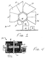
- FIG. 20 there is depicted by numeral 20 an example of a high pressure processing system, such as those manufactured by Applied Materials, Inc. of San Jose, California and Electrotech Ltd. of Bristol, U.K., that can be used to implement some of the processing measures of the present invention.
- the depicted high pressure system 20 is provided with a generally hexagonal, "hub and spoke” configuration, and includes a cassette handler 22 that is operable to convey one or more semiconductor wafer cassettes (not shown) from a cassette loading zone 24 through a pressure variable loading dock 26.
- the loading dock 26 is operable to cycle between different levels of vacuum as the cassettes are transported by the handler 22 between different process chambers, as will be described below.
- the cassette handler 22 is configured as a rotatable, extendible arm that is operable to transfer wafers from cassettes to the process chambers and back to cassettes as the wafers are processed by the device.
- a heating station 28 is provided to implement preliminary thermal processing that may be desired for the cassettes of wafers transported by the handler 22.
- the wafers can be transported by the handler 22 to a physical vapor deposition (“PVD”) station 30 for the deposition of cavity liner metals in accordance with the present invention.
- PVD physical vapor deposition
- the cassettes can be transferred by the handler 22 to one or more of the following stations for application of the cavity fill materials in accordance with the present invention: chemical vapor deposition ("CVD") station 32, high power/rapid deposition PVD station 33, soft sputter etch station 34; high density plasma sputter station 36; and high pressure processing station 38.
- Etch chamber 34 can optionally include a heating station (not shown) to facilitate thermal processing of the wafers during etching.
- a monitor 40 can optionally be connected to various control apparatus to provide a display of the progress of wafers through the device 20.
- a portion of a silicon wafer is illustrated following conventional processing, such as processing through a 0.35 ⁇ m CMOS Double-Level-Metal (DLM) flow (not shown) utilizing chemical mechanical planarization of the poly-metal-dielectric (PMD) and interlevel-metal-dielectric (IMD).
- PMD poly-metal-dielectric
- IMD interlevel-metal-dielectric
- Contacts, vias and trenches, such as via 42 shown in the drawing can be patterned in a dielectric layer 41 in a conventional manner, such as through use of phase shifted I-line lithography followed by plasma etch.
- Cavity fill is further affected by the "wetting or "dispersibility" between the fill metal and the material with which the fill metal contacts in the cavity 42.
- Material "wetting” relates to the ability of the material to cover a surface. The wetting between two materials is a function of the material surface tension and the interface energy. The affect of these parameters on cavity fill is graphically illustrated in Figs. 2A - 2C. In Fig. 2A, poor wetting between the fill material 43 and the cavity inner wall 44 is illustrated. Poor material wetting impedes the flow of material 43 into the cavity due to the frictional force ( ⁇ ) between the material 43 and the cavity wall 44, which opposes the application force ( ⁇ ) directing the material into the cavity.
- lead surface 43a of the fill material exhibits a convex contour, as the material resists engagement with the cavity wall 44.
- Trailing or upper fill material surface 43b exhibits a concave contour as a result of the net flow force (F) applied to the fill material.
- the flow force i.e., the force (F) that must be overcome to direct the fill material 43 into the cavity 42
- ⁇ the application of the application ( ⁇ ) and frictional ( ⁇ ) forces.
- optimal wetting of a fill material is related to the difference between the application force ( ⁇ ) and the frictional force ( ⁇ ).
- the lead surface 43a of the fill material exhibits a concave contour due to increased surface engagement with the cavity wall. It is therefore desirable to select materials for the fill material and the cavity wall which exhibit a low interface energy, the selection of which would allow for optimal wetting and a diminution in processing temperature. This is graphically illustrated in Fig.
- interface energy (E) As the value of interface energy (E) approaches zero, the contact angle ⁇ approaches zero.
- the interface energy E that is associated with application of a cavity fill material (as would occur incident to the filling of vias, contacts, trenches and the like), can be lowered through the application of the fill material in a two-stage, bi-layer process in accordance with the practice of the present invention.
- a via 42 that is formed in a dielectric layer 41 overlying a layer of Silicon 45.
- the dielectric layer can be comprised of any of a variety of known dielectrics having favorable electrical and processing characteristics, and can optionally be in the form of one of the newer generation low dielectric constant ( ⁇ ) dielectrics (i.e., ⁇ ⁇ 2.5) mentioned previously, for which the practice of the present invention is particularly advantageous.
- the cavity fill material designated generally by reference numeral 46, is in the form of a multi-level structure in which a cavity liner 46 ' is provided to facilitate wetting of a subsequently-applied second fill layer 46 '' , and thus optimize electrical conduction across the filled cavity.
- the liner 46 ' comprises a metal or metal alloy, such as: (1) Al - Cu( ⁇ 0.5 - ⁇ 4%); (2) Al - Ge( ⁇ 0.5 - ⁇ 5%) - Cu( ⁇ 0 - ⁇ 4%); (3) WSi x (2 ⁇ x ⁇ 2.4); (4) TiSi 2 ; (5) Al - Sc( ⁇ 0.1 - ⁇ 0.3%); (6) TiN; (7) TiW; (8) Tungsten; (9) Al( ⁇ 1%) - Si( ⁇ 1%) - Cu; (10) Al( ⁇ 1%) - Si( ⁇ 0.5%) - Sc; (11) Titanium; and (12) Titanium( ⁇ 0 - ⁇ 25%) -Aluminum alloys, any of the foregoing materials (1) - (12) being taken singularly or in combination with one another in a manner which facilitates "wetting" of an alloy second layer 46'' formed from any one or more of the foregoing metal alloys to fill the via
- the liner 46 ' is configured as an alloy liner
- the liner can be applied in discrete overlying metal layers which react to produce a liner of substantially uniform composition.
- a Ti - Al liner can be formed by first depositing a 5 - 10nm thick layer of Titanium, followed by deposition of an Aluminum layer up to about 100nm thick. The deposited liner layers react with one another to render a substantially uniform Ti-Al liner having an Al:Ti ratio of about 10-20:1.
- the Titanium liner layer can be applied at a temperature of up to about 350°C in a vacuum of about 3-5 mTorr.
- the Aluminum liner layer can be applied at a temperature of up to about 300°C at a vacuum of about 3-5 mTorr.
- Germanium and/or Silicon can be applied in the foregoing manner as discrete liner layers to react with Aluminum that is deposited as a liner layer to lower the Aluminum melting point and thereby lower its flow stress to further facilitate uniform deposition along the surface of the cavity.
- the liner 46 ' is preferably deposited at a temperature of no more than about 350°C at a deposition rate of about 1-2nm/sec to permit for higher conformity metal deposition within the cavity.
- deposition can be accomplished by high density plasma sputtering, chemical vapor deposition, collimated cold sputtering, or other suitable low temperature processes in dedicated stations 30 - 38 in the high pressure processing system 20 (Fig. 1) or other suitable apparatus that are capable of rendering a relatively uniform conductive metal layer 46 ' that is between about 50 - 100 nm thick along the surface 44 of the cavity.
- a second, comparatively dense cavity fill layer 46" can be deposited in overlying relation with the liner 46 ' by way of sputtering, chemical vapor deposition, or high density plasma deposition in accordance with the processing station selected from the wafer processing system 20. As is shown in the drawing of Fig. 3, the applied second layer 46'' is then driven into the cavity 42 at a pressure ⁇ that is sufficient to overcome the resistive force ⁇ to the inflow.
- Optimal wetting between the second layer 46'' and the liner 46 ' can be obtained as a result of the bi-layer fill, as the second, bulk metal layer 46'' bonds more readily to the liner 46 ' than the layer 46'' would bond to the cavity wall 44, as indicated by the concave configuration of lower surface 46''a of the second layer.
- the second layer 46'' is preferably applied at a relatively high deposition rate of about 15-20nm/sec at a temperature of about 350° - 400°C at a vacuum pressure of about 2 - 4 mTorr to ensure cavity mouth closure.
- the second cavity fill layer 46'' is preferably provided at a thickness of about 450 - 550 nm to render a total cavity metal fill of about 500 - 600 nm.
- the liner 46 ' provides a continuous conduction path across the via, even in instances where minor voids are present between the second layer 46'' and the liner 46 ' .
- Cavity fill is completed by application of pressure of about 500 - 1,200 atm, and preferably in the range of 650 - 1,000 atm., in a non-reactive, preferably inert gas, environment.
- Preferred inert gasses include helium and argon.
- the temperature and pressure parameters can be varied in accordance with such variables as the respective compositions of the liner 46 ' and second fill layer 46'' materials, and the like.
- Such high pressure processing can be accomplished under vacuum in a high pressure module 38 of the type discussed previously in connection with Fig. 1.
- a pressure module 38 as is more fully illustrated in Fig. 4, can include a high pressure chamber 48 having two radiant heaters 50a and 50b that are operable to provide for control of wafer processing temperature.
- the second fill layer 46'' can be forced into the semiconductor cavity 44 and associated liner 46' by pressurizing the chamber 48 with a suitable non-reactive or inert gas, such as argon, delivered through inlet 52, to accomplish substantially complete cavity filling.
- the second layer 46'' preferably comprises Aluminum, or an alloy such as any one of the following alloys: (1) Al - Cu( ⁇ 0.5 - ⁇ 4%); (2) Al - Ge( ⁇ 0.5 - ⁇ 5%) - Cu( ⁇ 0 - ⁇ 4%); (3) Al - Sc( ⁇ 0.1 - ⁇ 0.3%); (4) Al( ⁇ 1%) - Si( ⁇ 1%) - Cu; (5) Al( ⁇ 1%) - Si( ⁇ 0.5%) - Sc, or various combinations of the above which render a fill material exhibiting a resistivity that is preferably less than about 3.5 ⁇ -cm.
- the first and second cavity fill layers 46 ' & 46'' are formed of identical, or substantially identical, metal alloys so as to optimize wetting and minimize electrical resistance of the filled cavity.
- Figures 5A and 5B illustrate SEM cross sections of filled high aspect ratio vias.
- the vias extend through a BPSG-TEOS dielectric which overlies a Silicon layer.
- high pressure cavity fill is attempted in the absence of a "wetting" enhancing liner, resulting in incomplete cavity fill due to incomplete and irregular wetting of the fill material with the cavity walls.
- the darkened, irregular shaped portions appearing in each via are cavity voids where fill material did not flow.
- the illustrated via fill was accomplished by baking wafers at a temperature of about 380°C for a period of about four min., followed by via fill by deposition at a temperature of about 350°C of Al - Cu( ⁇ 0.5%) and high pressure extrusion at a pressure of about 650 atm. for about 1-3 minutes in Argon. No such darkened portions appear in Fig. 5B, which demonstrates the enhanced aluminum fill technique of the present invention, as substantially uniform via fill has been accomplished.
- Cavity fill was accomplished in Fig. 5B by baking the wafers at a temperature of about 350°C for a period of about four minutes, followed by sputter deposition of Titanium and TiN liner layers.
- An Al - Cu( ⁇ 0.5%) alloy was deposited by sputtering at a temperature of about 350°C, after which the Al-Cu was extruded in an Argon atmosphere into the via at a pressure of about 650 atm.
Applications Claiming Priority (2)
| Application Number | Priority Date | Filing Date | Title |
|---|---|---|---|
| US44749095A | 1995-05-23 | 1995-05-23 | |
| US447490 | 1995-05-23 |
Publications (2)
| Publication Number | Publication Date |
|---|---|
| EP0793268A2 true EP0793268A2 (de) | 1997-09-03 |
| EP0793268A3 EP0793268A3 (de) | 1999-03-03 |
Family
ID=23776586
Family Applications (1)
| Application Number | Title | Priority Date | Filing Date |
|---|---|---|---|
| EP96108163A Withdrawn EP0793268A3 (de) | 1995-05-23 | 1996-05-22 | Verfahren zum Füllen von Löchern in einer Halbleiteranordnung |
Country Status (5)
| Country | Link |
|---|---|
| US (1) | US6150252A (de) |
| EP (1) | EP0793268A3 (de) |
| JP (1) | JPH09223741A (de) |
| KR (1) | KR960042974A (de) |
| TW (1) | TW302513B (de) |
Cited By (3)
| Publication number | Priority date | Publication date | Assignee | Title |
|---|---|---|---|---|
| WO1999063591A1 (en) * | 1998-05-29 | 1999-12-09 | Conexant Systems, Inc. | Dual-damascene interconnect structures employing low-k dielectric materials |
| EP0975014A1 (de) * | 1998-07-24 | 2000-01-26 | Sharp Kabushiki Kaisha | Verbesserte CVD-Kupfer-Haftung durch Zwei-Schritt-Abscheidungsverfahren |
| EP0987752A2 (de) * | 1998-09-18 | 2000-03-22 | International Business Machines Corporation | Damaszen-Verbindung mit erhöhter Zuverlässigkeit und deren Herstellungsverfahren |
Families Citing this family (19)
| Publication number | Priority date | Publication date | Assignee | Title |
|---|---|---|---|---|
| JPH09115866A (ja) * | 1995-10-17 | 1997-05-02 | Mitsubishi Electric Corp | 半導体装置の製造方法 |
| KR100440418B1 (ko) * | 1995-12-12 | 2004-10-20 | 텍사스 인스트루먼츠 인코포레이티드 | 저압,저온의반도체갭충전처리방법 |
| US6054379A (en) * | 1998-02-11 | 2000-04-25 | Applied Materials, Inc. | Method of depositing a low k dielectric with organo silane |
| US6121126A (en) * | 1998-02-25 | 2000-09-19 | Micron Technologies, Inc. | Methods and structures for metal interconnections in integrated circuits |
| US6143655A (en) | 1998-02-25 | 2000-11-07 | Micron Technology, Inc. | Methods and structures for silver interconnections in integrated circuits |
| US6492694B2 (en) | 1998-02-27 | 2002-12-10 | Micron Technology, Inc. | Highly conductive composite polysilicon gate for CMOS integrated circuits |
| US6815303B2 (en) * | 1998-04-29 | 2004-11-09 | Micron Technology, Inc. | Bipolar transistors with low-resistance emitter contacts |
| JP2000106397A (ja) * | 1998-07-31 | 2000-04-11 | Sony Corp | 半導体装置における配線構造及びその形成方法 |
| US6486063B2 (en) * | 2000-03-02 | 2002-11-26 | Tokyo Electron Limited | Semiconductor device manufacturing method for a copper connection |
| US6723634B1 (en) * | 2002-03-14 | 2004-04-20 | Advanced Micro Devices, Inc. | Method of forming interconnects with improved barrier layer adhesion |
| US20050006770A1 (en) * | 2003-07-08 | 2005-01-13 | Valeriy Sukharev | Copper-low-K dual damascene interconnect with improved reliability |
| US7118801B2 (en) * | 2003-11-10 | 2006-10-10 | Gore Enterprise Holdings, Inc. | Aerogel/PTFE composite insulating material |
| US7101787B1 (en) | 2004-04-09 | 2006-09-05 | National Semiconductor Corporation | System and method for minimizing increases in via resistance by applying a nitrogen plasma after a titanium liner deposition |
| US7482266B2 (en) * | 2007-02-15 | 2009-01-27 | United Microelectronics Corp. | Method of forming composite opening and method of dual damascene process using the same |
| US7772123B2 (en) | 2008-06-06 | 2010-08-10 | Infineon Technologies Ag | Through substrate via semiconductor components |
| US8525343B2 (en) * | 2010-09-28 | 2013-09-03 | Taiwan Semiconductor Manufacturing Company, Ltd. | Device with through-silicon via (TSV) and method of forming the same |
| US8901701B2 (en) * | 2011-02-10 | 2014-12-02 | Chia-Sheng Lin | Chip package and fabrication method thereof |
| US9685366B1 (en) | 2016-04-21 | 2017-06-20 | International Business Machines Corporation | Forming chamferless vias using thermally decomposable porefiller |
| US10998221B2 (en) * | 2017-07-14 | 2021-05-04 | Micron Technology, Inc. | Semiconductor constructions having fluorocarbon material |
Citations (10)
| Publication number | Priority date | Publication date | Assignee | Title |
|---|---|---|---|---|
| EP0393381A2 (de) * | 1989-04-17 | 1990-10-24 | International Business Machines Corporation | Laminierungsverfahren zum Überdecken der Seitenwände einer Höhlung in einem Substrat sowie zur Füllung dieser Höhlung |
| US5108951A (en) * | 1990-11-05 | 1992-04-28 | Sgs-Thomson Microelectronics, Inc. | Method for forming a metal contact |
| EP0516344A1 (de) * | 1991-05-28 | 1992-12-02 | Electrotech Limited | Verfahren zum Füllen eines Hohraumes in einem Substrat |
| EP0526889A2 (de) * | 1991-08-06 | 1993-02-10 | Nec Corporation | Verfahren zum Aufbringen einer Metall- oder Passivierenschicht mit hoher Haftung über einem isolierten Halbleitersubstrat |
| US5219790A (en) * | 1991-07-17 | 1993-06-15 | Sharp Kabushiki Kaisha | Method for forming metallization layer of wiring in semiconductor integrated circuits |
| EP0586803A1 (de) * | 1992-08-12 | 1994-03-16 | Applied Materials, Inc. | Verfahren zur Herstellung von Via-Verbindungen mit geringem Widerstand aus Aluminium, verbunden mit einer darüberliegenden Schaltungsschicht aus Metall für integrierte Schaltungsstruktur |
| WO1994013008A2 (en) * | 1992-11-19 | 1994-06-09 | Electrotech Limited | Forming a layer |
| US5355020A (en) * | 1991-07-08 | 1994-10-11 | Samsung Electronics Co., Ltd. | Semiconductor device having a multi-layer metal contact |
| WO1996002939A1 (en) * | 1994-07-13 | 1996-02-01 | Electrotech Limited | Method of introducing material in holes |
| EP0731503A2 (de) * | 1994-12-12 | 1996-09-11 | Texas Instruments Incorporated | Verfahren zum Füllen eines Halbleiterhohlraumes |
Family Cites Families (9)
| Publication number | Priority date | Publication date | Assignee | Title |
|---|---|---|---|---|
| JPH0199216A (ja) * | 1987-10-13 | 1989-04-18 | Fujitsu Ltd | 半導体装置の製造方法 |
| US5008216A (en) * | 1988-10-03 | 1991-04-16 | International Business Machines Corporation | Process for improved contact stud structure for semiconductor devices |
| JP2697796B2 (ja) * | 1988-11-14 | 1998-01-14 | 東京エレクトロン株式会社 | 半導体装置の製造方法 |
| US5073518A (en) * | 1989-11-27 | 1991-12-17 | Micron Technology, Inc. | Process to mechanically and plastically deform solid ductile metal to fill contacts of conductive channels with ductile metal and process for dry polishing excess metal from a semiconductor wafer |
| US5011793A (en) * | 1990-06-19 | 1991-04-30 | Nihon Shinku Gijutsu Kabushiki Kaisha | Vacuum deposition using pressurized reflow process |
| CA2061119C (en) * | 1991-04-19 | 1998-02-03 | Pei-Ing P. Lee | Method of depositing conductors in high aspect ratio apertures |
| US5371042A (en) * | 1992-06-16 | 1994-12-06 | Applied Materials, Inc. | Method of filling contacts in semiconductor devices |
| US5356836A (en) * | 1993-08-19 | 1994-10-18 | Industrial Technology Research Institute | Aluminum plug process |
| US5523259A (en) * | 1994-12-05 | 1996-06-04 | At&T Corp. | Method of forming metal layers formed as a composite of sub-layers using Ti texture control layer |
-
1996
- 1996-05-22 KR KR19960018076A patent/KR960042974A/ko not_active Application Discontinuation
- 1996-05-22 EP EP96108163A patent/EP0793268A3/de not_active Withdrawn
- 1996-05-23 JP JP8128523A patent/JPH09223741A/ja active Pending
- 1996-05-29 US US08/654,810 patent/US6150252A/en not_active Expired - Lifetime
- 1996-07-10 TW TW085108325A patent/TW302513B/zh not_active IP Right Cessation
Patent Citations (10)
| Publication number | Priority date | Publication date | Assignee | Title |
|---|---|---|---|---|
| EP0393381A2 (de) * | 1989-04-17 | 1990-10-24 | International Business Machines Corporation | Laminierungsverfahren zum Überdecken der Seitenwände einer Höhlung in einem Substrat sowie zur Füllung dieser Höhlung |
| US5108951A (en) * | 1990-11-05 | 1992-04-28 | Sgs-Thomson Microelectronics, Inc. | Method for forming a metal contact |
| EP0516344A1 (de) * | 1991-05-28 | 1992-12-02 | Electrotech Limited | Verfahren zum Füllen eines Hohraumes in einem Substrat |
| US5355020A (en) * | 1991-07-08 | 1994-10-11 | Samsung Electronics Co., Ltd. | Semiconductor device having a multi-layer metal contact |
| US5219790A (en) * | 1991-07-17 | 1993-06-15 | Sharp Kabushiki Kaisha | Method for forming metallization layer of wiring in semiconductor integrated circuits |
| EP0526889A2 (de) * | 1991-08-06 | 1993-02-10 | Nec Corporation | Verfahren zum Aufbringen einer Metall- oder Passivierenschicht mit hoher Haftung über einem isolierten Halbleitersubstrat |
| EP0586803A1 (de) * | 1992-08-12 | 1994-03-16 | Applied Materials, Inc. | Verfahren zur Herstellung von Via-Verbindungen mit geringem Widerstand aus Aluminium, verbunden mit einer darüberliegenden Schaltungsschicht aus Metall für integrierte Schaltungsstruktur |
| WO1994013008A2 (en) * | 1992-11-19 | 1994-06-09 | Electrotech Limited | Forming a layer |
| WO1996002939A1 (en) * | 1994-07-13 | 1996-02-01 | Electrotech Limited | Method of introducing material in holes |
| EP0731503A2 (de) * | 1994-12-12 | 1996-09-11 | Texas Instruments Incorporated | Verfahren zum Füllen eines Halbleiterhohlraumes |
Cited By (5)
| Publication number | Priority date | Publication date | Assignee | Title |
|---|---|---|---|---|
| WO1999063591A1 (en) * | 1998-05-29 | 1999-12-09 | Conexant Systems, Inc. | Dual-damascene interconnect structures employing low-k dielectric materials |
| US6627539B1 (en) | 1998-05-29 | 2003-09-30 | Newport Fab, Llc | Method of forming dual-damascene interconnect structures employing low-k dielectric materials |
| EP0975014A1 (de) * | 1998-07-24 | 2000-01-26 | Sharp Kabushiki Kaisha | Verbesserte CVD-Kupfer-Haftung durch Zwei-Schritt-Abscheidungsverfahren |
| EP0987752A2 (de) * | 1998-09-18 | 2000-03-22 | International Business Machines Corporation | Damaszen-Verbindung mit erhöhter Zuverlässigkeit und deren Herstellungsverfahren |
| EP0987752A3 (de) * | 1998-09-18 | 2003-10-22 | International Business Machines Corporation | Damaszen-Verbindung mit erhöhter Zuverlässigkeit und deren Herstellungsverfahren |
Also Published As
| Publication number | Publication date |
|---|---|
| EP0793268A3 (de) | 1999-03-03 |
| US6150252A (en) | 2000-11-21 |
| JPH09223741A (ja) | 1997-08-26 |
| TW302513B (de) | 1997-04-11 |
| KR960042974A (de) | 1996-12-21 |
Similar Documents
| Publication | Publication Date | Title |
|---|---|---|
| EP0793268A2 (de) | Verfahren zum Füllen von Löchern in einer Halbleiteranordnung | |
| JP3435194B2 (ja) | 半導体装置の配線層形成方法及び半導体装置 | |
| EP0485130B1 (de) | Verfahren zum Herstellen eines Metallkontaktes | |
| US5985763A (en) | Method for producing barrier-less plug structures | |
| EP0655780B1 (de) | Herstellungsverfahren von einem Aluminiumkontakt | |
| US6482735B1 (en) | Method for improved metal fill by treatment of mobility layers | |
| US5789317A (en) | Low temperature reflow method for filling high aspect ratio contacts | |
| JP2545184B2 (ja) | 半導体装置およびその製造方法 | |
| US5668055A (en) | Method of filling of contact openings and vias by self-extrusion of overlying compressively stressed matal layer | |
| US5700718A (en) | Method for increased metal interconnect reliability in situ formation of titanium aluminide | |
| US6589865B2 (en) | Low pressure, low temperature, semiconductor gap filling process | |
| GB2253939A (en) | Forming a metal layer on a semiconductor device | |
| US6713407B1 (en) | Method of forming a metal nitride layer over exposed copper | |
| US5747879A (en) | Interface between titanium and aluminum-alloy in metal stack for integrated circuit | |
| EP0488628B1 (de) | Verfahren zum Herstellen von gestapelten Verbindungs/kontaktlöchern aus Aluminium für Mehrschichtverbindungen | |
| EP0731503A2 (de) | Verfahren zum Füllen eines Halbleiterhohlraumes | |
| JP4799715B2 (ja) | 多層メタリゼーション用低温アルミニウムリフロー | |
| US6093968A (en) | Germanium alloy contact to a silicon substrate | |
| US20030190801A1 (en) | Method for forming a metal extrusion free via | |
| US6271137B1 (en) | Method of producing an aluminum stacked contact/via for multilayer | |
| US6605531B1 (en) | Hole-filling technique using CVD aluminum and PVD aluminum integration | |
| US6110829A (en) | Ultra-low temperature Al fill for sub-0.25 μm generation of ICs using an Al-Ge-Cu alloy | |
| EP0746026A2 (de) | Verbesserungen in oder in Bezug auf Halbleiterprodukte |
Legal Events
| Date | Code | Title | Description |
|---|---|---|---|
| PUAI | Public reference made under article 153(3) epc to a published international application that has entered the european phase |
Free format text: ORIGINAL CODE: 0009012 |
|
| AK | Designated contracting states |
Kind code of ref document: A2 Designated state(s): DE FR GB IT NL |
|
| PUAL | Search report despatched |
Free format text: ORIGINAL CODE: 0009013 |
|
| AK | Designated contracting states |
Kind code of ref document: A3 Designated state(s): DE FR GB IT NL |
|
| RHK1 | Main classification (correction) |
Ipc: H01L 21/768 |
|
| STAA | Information on the status of an ep patent application or granted ep patent |
Free format text: STATUS: THE APPLICATION IS DEEMED TO BE WITHDRAWN |
|
| 18D | Application deemed to be withdrawn |
Effective date: 19991001 |