EP0792690B1 - Enclume pour concasseur à impact centrifuge et cercle d'enclumes équipé de telles enclumes - Google Patents
Enclume pour concasseur à impact centrifuge et cercle d'enclumes équipé de telles enclumes Download PDFInfo
- Publication number
- EP0792690B1 EP0792690B1 EP97200301A EP97200301A EP0792690B1 EP 0792690 B1 EP0792690 B1 EP 0792690B1 EP 97200301 A EP97200301 A EP 97200301A EP 97200301 A EP97200301 A EP 97200301A EP 0792690 B1 EP0792690 B1 EP 0792690B1
- Authority
- EP
- European Patent Office
- Prior art keywords
- anvils
- anvil
- flanks
- ring
- bases
- Prior art date
- Legal status (The legal status is an assumption and is not a legal conclusion. Google has not performed a legal analysis and makes no representation as to the accuracy of the status listed.)
- Expired - Lifetime
Links
Images


Classifications
-
- B—PERFORMING OPERATIONS; TRANSPORTING
- B02—CRUSHING, PULVERISING, OR DISINTEGRATING; PREPARATORY TREATMENT OF GRAIN FOR MILLING
- B02C—CRUSHING, PULVERISING, OR DISINTEGRATING IN GENERAL; MILLING GRAIN
- B02C13/00—Disintegrating by mills having rotary beater elements ; Hammer mills
- B02C13/14—Disintegrating by mills having rotary beater elements ; Hammer mills with vertical rotor shaft, e.g. combined with sifting devices
- B02C13/18—Disintegrating by mills having rotary beater elements ; Hammer mills with vertical rotor shaft, e.g. combined with sifting devices with beaters rigidly connected to the rotor
- B02C13/1807—Disintegrating by mills having rotary beater elements ; Hammer mills with vertical rotor shaft, e.g. combined with sifting devices with beaters rigidly connected to the rotor the material to be crushed being thrown against an anvil or impact plate
- B02C13/185—Construction or shape of anvil or impact plate
-
- B—PERFORMING OPERATIONS; TRANSPORTING
- B02—CRUSHING, PULVERISING, OR DISINTEGRATING; PREPARATORY TREATMENT OF GRAIN FOR MILLING
- B02C—CRUSHING, PULVERISING, OR DISINTEGRATING IN GENERAL; MILLING GRAIN
- B02C13/00—Disintegrating by mills having rotary beater elements ; Hammer mills
- B02C13/26—Details
- B02C13/28—Shape or construction of beater elements
Definitions
- the present invention relates to an anvil for centrifugal impact crusher having overall the shape of a triangular prism, comprising two bases and surfaces lateral of which a lateral surface is a surface cylindrical with a determined radius of curvature and of which two other side surfaces have sides respectively adjacent to the cylindrical surface, these flanks being oriented towards the axis of curvature of said surface cylindrical.
- the invention also relates to a circle anvil for centrifugal impact crusher comprising a cylindrical anvil ring with an inner and lower radial flange to support vertically a garnish of the kind above which are wedged inside the ring anvil holder by vault effect.
- a crusher with such an anvil circle is described in document US 5,184,784.
- the anvils are freely placed at inside the anvil ring and there are retained by arch effect without any fixing particular.
- maintaining the anvils by arching effect allows a better distribution of shocks and stresses on the anvil ring and a longer duration of the whole.
- the object of the present invention is to provide a new anvil as well as an equipped anvil circle such anvils also fixed by arch effect but which make it easier to set up and replacement of the anvils individually.
- the present invention provides for an anvil of the kind described in the preamble which is essentially characterized in that the two sides adjacent to the cylindrical surface are inclined with respect to a median plane of symmetry of the anvil passing through the axis of curvature of the cylindrical surface, the inclinations of the two sides being identical over the entire height of the anvil and opposite directions, so that the two sides converge towards one of the bases.
- the inclination of these sides is preferably in the range of 3 ° -15 °.
- One of the bases of the anvil, preferably that towards which the said sides diverge comprises two let's stick out.
- the invention also provides a circle of anvils equipped with an even number of such anvils which are oriented, vertically, alternately in one direction and in the other.
- the inner flange of the anvil ring has openings serving as housing for the studs anvils which are oriented with the tenons towards the low.
- the installation of new anvils consists simply place half of the anvils first with the tenons facing down and anchor these in the openings provided for this purpose in the flange of the anvil ring and then slide into the spaces remaining between these anvils placed those which are oriented with the tenons up or those which do not have studs.
- the establishment of these last anvils is aided by the tilt lateral flanks which automatically guide the anvils on their seat.
- FIG 1 shows an anvil circle similar to that described in document US 5,184,784 but equipped, in the example shown, of 18 individual anvils 10 according to the present invention. These anvils garnish the inner surface of a circular anvil ring 12 shown in Figure 2.
- This ring 12 has, at its base, an inner radial flange 14 intended to support the anvil lining 10.
- An anvil 10 according to the present invention is shown in Figures 3 to 5.
- Such an anvil 10, cast in an alloy having good resistance to shock generally has the shape of a prism, of preferably single triangular section with one side rear cylindrical 16 intended to follow the curvature of the ring 12, two side faces 18 and 20 and two bases 22 and 24.
- the two side surfaces 18 and 20 have, at their junction with the cylindrical surface rear 16, two sides 26 and 28 which form spoils with an inclination that can vary between 3 ° and 15 ° from the vertical, thus giving the anvil 10 a slightly frustoconical shape like the shown in Figure 5.
- the side surfaces 18, 20 themselves can be vertical or also be slightly inclined like their sides 26 and 28.
- the plan of the flanks 26 and 28 is, moreover, overall perpendicular to the cylindrical face 16, that is to say oriented towards the axis of curvature of this surface 16 so maintain the anvils 10 by vault as in the aforementioned patent.
- the widest base of the anvil i.e. the one towards which the sides 26 and 28 diverge, has two studs 30, while the flange 14 of the anvil ring has openings 32 forming housings for these tenons 30.
- Figure 6 schematically illustrates the implementation place anvils in the anvil ring 12 to make the circle of anvils shown in Figure 1.
- the nine anvils remaining 10a are then slid, with the tenons 30 oriented upwards, in the spaces remaining between the anvils 10 previously put in place.
- the anvils 10a and their housings between anvils 10 already placed have complementary conicities, so the placement of the anvils is extremely easy since they are automatically guided in place.
- Anvils 10a oriented with the studs 30 upwards can be individually lifted out of their homes, the other anvils 10 and 10a remaining in place as they are wedged radially by arching effect and that they cannot move sideways because of anvils which are trapped by their tenons 30 in the housings 32 of the ring 12. This allows replacement individual anvils in the crusher without require dismantling the anvil ring.
- Anvils 10 which are anchored by their tenons 30 in flange 14 can also be removed individually but, because of the spoils of sides 26 and 28, we must first clear the two neighboring anvils 10a.
- each anvil can be equipped with a means of appropriate entry, symbolized, in the example shown, by a bore 34 passing vertically each anvil.
- tenons in anvils and dwellings can also be reversed in the measure that the housings 32 of the ring 12 can be replaced by studs and that the 30 studs of anvils can be replaced with cavities for receive the tenons of the ring.
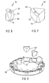
- Figures 7 and 8 show the two anvils of an embodiment which provides for two types different anvils as gathered in the circle anvils shown in Figure 9.
- Anvils 40 of Figure 7 are anvils proper and correspond to the anvils 10 of the previous figures. These anvils 40 also have a cylindrical face rear 42 and two sides 44 and 46 oriented on the axis of curvature of the face 42 to be wedged by effect of vault and inclined from 3 ° to 15 ° relative to the vertical. However, unlike anvils 10, the anvils 40 are devoid of tenons.
- the anvils 50 in Figure 8 are actually mini anvils which, although also receiving material to be crushed, rather serve as spacers serving to wedge the anvils 40 proper.
- the anvils 50 also have a cylindrical face rear 52 and lateral flanks 54 and 56 oriented on the axis of curvature of the rear face and a draft with respect to the vertical identical to that of anvils 40 but in opposite directions.
- Anvils 50 also each have a pin 58 on the base towards which the sides 54, 56 diverge, on the Figure 8, the lower base.
- anvils 40 and 50 The placement of anvils 40 and 50 is similar to that of the previous embodiment knowing that each anvil 40 must be surrounded by two anvils 50 and vice versa. First place the anvils 50 in ensuring that their tenon 50 is anchored in the corresponding housings of the ring. Then just slide the anvils 40 between the anvils 50 previously laid, the slopes of their sides 44 and 46 and those of the sides 54 and 56 of the anvils 50 automatically guiding them to the correct position.
- Figure 9 is essentially intended to replace that of the previous Figures to reduce the number of anvils when the nature of the material to be crushed on demand.
Landscapes
- Engineering & Computer Science (AREA)
- Food Science & Technology (AREA)
- Crushing And Pulverization Processes (AREA)
- Disintegrating Or Milling (AREA)
- Toys (AREA)
- Crushing And Grinding (AREA)
Description
- la Figure 1 représente schématiquement une vue en plan d'un premier mode de réalisation d'un cercle d'enclumes selon la présente invention ;
- la Figure 2 représente schématiquement une vue en perspective d'un anneau porte-enclumes ;
- la Figure 3 représente une vue en perspective d'un premier mode de réalisation d'une enclume avec les tenons tournés vers le haut ;
- la Figure 4 représente l'enclume en perspective avec les tenons tournés vers le bas ;
- la Figure 5 représente une vue en élévation de l'enclume ;
- la Figure 6 représente une vue en perspective illustrant schématiquement la mise en place des enclumes ;
- les Figures 7 et 8 représentent schématiquement des vues en perspective de deux types d'enclumes d'un second mode de réalisation ; et
- la Figure 9 représente une vue en perspective illustrant schématiquement la mise en place des enclumes du second mode de réalisation.
Claims (11)
- Enclume pour concasseur à impact centrifuge ayant globalement la forme d'un prisme triangulaire comprenant deux bases (22, 24) et des surfaces latérales dont une surface latérale (16) (42) (52) est une surface cylindrique avec un rayon de courbure déterminé et dont deux autres surfaces latérales (18, 20) ont des flancs (26, 28) (44, 46) (54, 56) respectivement adjacents à la surface cylindrique (16) (42) (52), ces flancs (26, 28) (44, 46) (54, 56) étant orientés vers l'axe de courbure de ladite surface cylindrique (16) (42) (52), caractérisée en ce que les deux flancs (26, 28) (44, 46) (54, 56) sont inclinés par rapport à un plan médian de symétrie de l'enclume (10) (40) (50) passant par l'axe de courbure de la surface cylindrique (16) (42) (52), les inclinaisons des deux flancs (26, 28) (44, 46) (54, 56) étant identiques sur toute la hauteur de l'enclume et de sens opposés, de sorte que les deux flancs (26, 28) (44, 46) (54, 56) convergent vers l'une des deux bases (22, 24).
- Enclume selon la revendication 1, caractérisée en ce que lesdites inclinaisons des flancs (26, 28) (44, 46) (54, 56) sont de l'ordre de 3°-15°.
- Enclume selon l'une quelconque des revendications 1 ou 2, caractérisée en ce que l'une des bases (22) comporte deux tenons saillants (30).
- Enclume selon l'une quelconque des revendications 1 ou 2, caractérisée en ce que l'une des bases comporte un tenon saillant (58).
- Enclume selon les revendications 3 et 4, caractérisée en ce que les tenons (30) (58) se trouvent sur la base vers laquelle les flancs (26, 28) (54, 56) divergent.
- Cercle d'enclumes pour concasseur à impact centrifuge comprenant un anneau porte-enclumes cylindrique (12) (60) avec une bride (14) radiale intérieure et inférieure pour supporter verticalement une garniture d'enclumes (10) (40) (50) qui ont globalement la forme d'un prisme triangulaire comprenant deux bases (22, 24) et des surfaces latérales dont une surface latérale est une surface cylindrique (16) (42) (52) de même rayon de courbure que celui de l'anneau porte-enclumes (12) (60) et dont deux autres surfaces latérales (18, 20) ont des flancs (26, 28) (44, 46) (54, 56) respectivement adjacents à la surface cylindrique (16) (42) (52) et orientés vers le centre de l'anneau porte-enclumes (12) (60), les enclumes étant calées à l'intérieur de l'anneau porte-enclumes (12) (60) par effet de voûte, caractérisé en ce que lesdits flancs (26, 28) (44, 46) (54, 56) des surfaces latérales (18, 20) sont inclinés par rapport à un plan médian de symétrie radial de l'enclume (10) (40) (50) passant par l'axe central de l'anneau porte-enclumes (12) (60), les inclinaisons des deux flancs (26, 28) (44, 46) (54, 56) étant identiques sur toute la hauteur de l'enclume et de sens opposés, de sorte que les deux flancs (26,28) (44,46) (54,56) convergent vers l'une des deux bases (22, 24).
- Cercle d'enclumes selon la revendication 6, caractérisé en ce que toutes les enclumes (10) sont identiques entre elles et orientées verticalement, alternativement dans un sens et dans l'autre.
- Cercle d'enclumes selon la revendication 6, caractérisé par deux groupes d'enclumes (40) (50) de tailles différentes, chaque enclume d'un groupe étant entourée de deux enclumes de l'autre groupe et vice-versa.
- Cercle d'enclumes selon la revendication 6, caractérisé en ce que les inclinaisons desdits flancs (26, 28) (44, 46) (54, 56) sont de l'ordre de 3°-15°.
- Cercle d'enclumes selon la revendication 7, caractérisé en ce que les enclumes (10) comportent, sur l'une des bases (22), deux tenons (30) et en ce que la bride intérieure (14) de l'anneau porte-enclumes (12) comporte des ouvertures correspondantes (32) pour recevoir lesdits tenons (30).
- Cercle d'enclumes selon la revendication 8, caractérisé en ce que les enclumes (50) d'un des groupes comportent un tenon (58) à l'une de leurs bases et en ce que la bride intérieure de l'anneau porte-enclumes (60) comporte des ouvertures correspondantes pour recevoir lesdits tenons (58).
Applications Claiming Priority (2)
| Application Number | Priority Date | Filing Date | Title |
|---|---|---|---|
| BE9600168 | 1996-02-27 | ||
| BE9600168A BE1010037A3 (fr) | 1996-02-27 | 1996-02-27 | Enclume pour concasseur a impact centrifuge et cercle d'enclumes equipe de telles enclumes. |
Publications (2)
| Publication Number | Publication Date |
|---|---|
| EP0792690A1 EP0792690A1 (fr) | 1997-09-03 |
| EP0792690B1 true EP0792690B1 (fr) | 2001-05-30 |
Family
ID=3889569
Family Applications (1)
| Application Number | Title | Priority Date | Filing Date |
|---|---|---|---|
| EP97200301A Expired - Lifetime EP0792690B1 (fr) | 1996-02-27 | 1997-02-04 | Enclume pour concasseur à impact centrifuge et cercle d'enclumes équipé de telles enclumes |
Country Status (16)
| Country | Link |
|---|---|
| US (1) | US5806774A (fr) |
| EP (1) | EP0792690B1 (fr) |
| JP (1) | JPH09225328A (fr) |
| KR (1) | KR970061364A (fr) |
| AT (1) | ATE201614T1 (fr) |
| AU (1) | AU703900B2 (fr) |
| BE (1) | BE1010037A3 (fr) |
| BR (1) | BR9700317A (fr) |
| CA (1) | CA2198170A1 (fr) |
| CZ (1) | CZ287004B6 (fr) |
| DE (1) | DE69704970T2 (fr) |
| ES (1) | ES2157046T3 (fr) |
| MX (1) | MX9701422A (fr) |
| PL (1) | PL187495B1 (fr) |
| PT (1) | PT792690E (fr) |
| SK (1) | SK281962B6 (fr) |
Families Citing this family (11)
| Publication number | Priority date | Publication date | Assignee | Title |
|---|---|---|---|---|
| DE69822382T2 (de) | 1997-08-21 | 2004-07-29 | Nissan Motor Co., Ltd., Yokohama | Abgasreinigungssystem für eine Brennkraftmaschine |
| WO1999014314A1 (fr) | 1997-09-12 | 1999-03-25 | Commonwealth Scientific And Industrial Research Organisation | Regulation de l'expression genique dans les plantes |
| US6227472B1 (en) * | 1999-11-20 | 2001-05-08 | Robert Ryan | Stonecrusher with externally adjustable anvil ring |
| AUPR858301A0 (en) * | 2001-10-30 | 2001-11-29 | Crushing & Mining Equipment Pty Ltd | An impactor anvil |
| USD491587S1 (en) | 2003-04-21 | 2004-06-15 | Cedric J. Clark | Mobile rock crusher hammer |
| US7090159B2 (en) | 2004-03-23 | 2006-08-15 | Kennametal Inc. | Invertible center feed disk for a vertical shaft impact crusher |
| WO2013127507A1 (fr) | 2012-02-29 | 2013-09-06 | DICHTER, Ingrid | Élément de percussion pour broyeur à percussion à arbre vertical |
| US9757731B2 (en) | 2013-09-11 | 2017-09-12 | Didion Manufacturing Company | Interlocking liner segments for a tumbling unit |
| US10668478B2 (en) | 2013-09-11 | 2020-06-02 | Distron Manufacturing Co. | Multi directional rifling and multi flow variable speed rifling for liner segments for crushers, reclaimers, separators and cleaners for products |
| KR101476958B1 (ko) | 2014-06-11 | 2014-12-24 | 하용간 | 수직축 충격 파쇄기 및 그 회전자 |
| WO2018005836A1 (fr) | 2016-06-29 | 2018-01-04 | Superior Industries, Inc. | Broyeur à percussion à arbre vertical |
Family Cites Families (9)
| Publication number | Priority date | Publication date | Assignee | Title |
|---|---|---|---|---|
| US3088685A (en) * | 1961-06-26 | 1963-05-07 | Thomas E Bridgewater | Breaker plate structure for impact crusher and retaining means therefor |
| US3093329A (en) * | 1961-06-28 | 1963-06-11 | Thomas E Bridgewater | Breaker plate structure |
| US3474974A (en) * | 1967-02-27 | 1969-10-28 | Bruce V Wood | Impact type crusher |
| US4090673A (en) * | 1977-02-18 | 1978-05-23 | Canica Crushers Ltd. | Centrifugal impact rock crushers |
| AU565386B2 (en) * | 1982-11-29 | 1987-09-17 | Kubota Ltd. | Impact crusher with adjustable crushing gap |
| US4768724A (en) * | 1986-03-25 | 1988-09-06 | Guy Ehmann | Breaker plate for rock crusher |
| US4756484A (en) * | 1986-09-22 | 1988-07-12 | Nordberg, Inc. | Vertical shaft impact crusher with interchangeable crusher ring segments |
| US5029761A (en) * | 1989-11-30 | 1991-07-09 | Nordberg Inc. | Liner wear insert for vertical shaft impactor rotor |
| US5184784A (en) * | 1990-08-15 | 1993-02-09 | Canica Crushers, Inc. | Anvil for use in a centrifugal impact crusher |
-
1996
- 1996-02-27 BE BE9600168A patent/BE1010037A3/fr not_active IP Right Cessation
-
1997
- 1997-02-04 DE DE69704970T patent/DE69704970T2/de not_active Expired - Fee Related
- 1997-02-04 ES ES97200301T patent/ES2157046T3/es not_active Expired - Lifetime
- 1997-02-04 AT AT97200301T patent/ATE201614T1/de not_active IP Right Cessation
- 1997-02-04 EP EP97200301A patent/EP0792690B1/fr not_active Expired - Lifetime
- 1997-02-04 PT PT97200301T patent/PT792690E/pt unknown
- 1997-02-12 AU AU12632/97A patent/AU703900B2/en not_active Ceased
- 1997-02-19 US US08/803,191 patent/US5806774A/en not_active Expired - Fee Related
- 1997-02-20 CA CA002198170A patent/CA2198170A1/fr not_active Abandoned
- 1997-02-24 PL PL97318631A patent/PL187495B1/pl not_active IP Right Cessation
- 1997-02-25 SK SK257-97A patent/SK281962B6/sk unknown
- 1997-02-25 MX MX9701422A patent/MX9701422A/es not_active Application Discontinuation
- 1997-02-25 KR KR1019970005814A patent/KR970061364A/ko not_active Withdrawn
- 1997-02-25 CZ CZ1997573A patent/CZ287004B6/cs not_active IP Right Cessation
- 1997-02-25 JP JP9057014A patent/JPH09225328A/ja not_active Abandoned
- 1997-02-27 BR BR9700317A patent/BR9700317A/pt not_active Application Discontinuation
Also Published As
| Publication number | Publication date |
|---|---|
| PT792690E (pt) | 2001-10-30 |
| BE1010037A3 (fr) | 1997-12-02 |
| US5806774A (en) | 1998-09-15 |
| MX9701422A (es) | 1997-08-30 |
| CZ57397A3 (en) | 1997-11-12 |
| AU703900B2 (en) | 1999-04-01 |
| PL318631A1 (en) | 1997-09-01 |
| BR9700317A (pt) | 1998-10-27 |
| AU1263297A (en) | 1997-09-04 |
| PL187495B1 (pl) | 2004-07-30 |
| SK25797A3 (en) | 1997-10-08 |
| KR970061364A (ko) | 1997-09-12 |
| EP0792690A1 (fr) | 1997-09-03 |
| CA2198170A1 (fr) | 1997-08-27 |
| JPH09225328A (ja) | 1997-09-02 |
| SK281962B6 (sk) | 2001-09-11 |
| ATE201614T1 (de) | 2001-06-15 |
| DE69704970T2 (de) | 2001-11-15 |
| ES2157046T3 (es) | 2001-08-01 |
| DE69704970D1 (de) | 2001-07-05 |
| CZ287004B6 (en) | 2000-08-16 |
Similar Documents
| Publication | Publication Date | Title |
|---|---|---|
| BE1010037A3 (fr) | Enclume pour concasseur a impact centrifuge et cercle d'enclumes equipe de telles enclumes. | |
| EP0083289B1 (fr) | Roue de rotor de turbomachine munie d'un dispositif de retenue axiale et radiale d'aubes sur le disque | |
| EP2672331B1 (fr) | Boîte de pièce d'horlogerie comprenant un élément d'habillage à fixation ameliorée | |
| EP2719866B1 (fr) | Roue de turbomachine avec un verrou de blocage d'aubes | |
| EP2525019A1 (fr) | Dispositif de lestage d'un garde-corps | |
| EP0347388A1 (fr) | Barrière modulaire évolutive pour définir un périmètre de protection | |
| FR2504575A1 (fr) | Plafond suspendu | |
| EP2275324B1 (fr) | Système de contrepoids pour tracteur, notamment de type agricole | |
| FR3053283A1 (fr) | Dispositif de roulage a plat pour vehicule automobile et ensemble monte l'incorporant | |
| EP3787432B1 (fr) | Bague joaillière ajustable comportant des plaquettes d'ajustement | |
| EP3787433B1 (fr) | Bague joaillière ajustable comprenant des moyens de guidage | |
| FR2537830A1 (fr) | Tambour de convoyage pour acheminer du fourrage dans un vehicule a chargement automatique | |
| CH651087A5 (fr) | Element d'ossature de support pour plaques ou grilles de couverture et plaque ou grille de couverture correspondante. | |
| FR2617413A1 (fr) | Coiffe pour recouvrir de tous cotes les corps porteurs d'un rotor de concasseur a marteaux | |
| EP0875184B1 (fr) | Système de suspension de lattes | |
| BE1009998A3 (fr) | Rotor pour concasseur a percussion. | |
| FR2829777A1 (fr) | Dispositif d'ancrage au sol d'un objet | |
| EP3842597B1 (fr) | Système de connexion articulé pour éléments portants | |
| FR2870012A1 (fr) | Monture de lunettes associee par pression a un element de transformation | |
| FR2715189A1 (fr) | Paire de voussoirs conjugués destinés à la réalisation d'un tunnel et voussoirs d'une telle paire. | |
| BE1028105B1 (fr) | Système de connexion articulé pour éléments portants | |
| WO1999017638A1 (fr) | Meuble compose d'elements assemblables | |
| FR2917761A1 (fr) | Plancher demontable | |
| CH693620A5 (fr) | Support pour appareillage(s) à loger dans une boîte. | |
| FR2682698A3 (en) | Adaptive modular barrier for defining a protected perimeter |
Legal Events
| Date | Code | Title | Description |
|---|---|---|---|
| PUAI | Public reference made under article 153(3) epc to a published international application that has entered the european phase |
Free format text: ORIGINAL CODE: 0009012 |
|
| AK | Designated contracting states |
Kind code of ref document: A1 Designated state(s): AT BE DE ES FR GB IT PT |
|
| 17P | Request for examination filed |
Effective date: 19980122 |
|
| 17Q | First examination report despatched |
Effective date: 20000113 |
|
| GRAG | Despatch of communication of intention to grant |
Free format text: ORIGINAL CODE: EPIDOS AGRA |
|
| RAP1 | Party data changed (applicant data changed or rights of an application transferred) |
Owner name: MAGOTTEAUX INTERNATIONAL |
|
| GRAG | Despatch of communication of intention to grant |
Free format text: ORIGINAL CODE: EPIDOS AGRA |
|
| GRAH | Despatch of communication of intention to grant a patent |
Free format text: ORIGINAL CODE: EPIDOS IGRA |
|
| GRAH | Despatch of communication of intention to grant a patent |
Free format text: ORIGINAL CODE: EPIDOS IGRA |
|
| GRAA | (expected) grant |
Free format text: ORIGINAL CODE: 0009210 |
|
| AK | Designated contracting states |
Kind code of ref document: B1 Designated state(s): AT BE DE ES FR GB IT PT |
|
| REF | Corresponds to: |
Ref document number: 201614 Country of ref document: AT Date of ref document: 20010615 Kind code of ref document: T |
|
| GBT | Gb: translation of ep patent filed (gb section 77(6)(a)/1977) |
Effective date: 20010530 |
|
| REF | Corresponds to: |
Ref document number: 69704970 Country of ref document: DE Date of ref document: 20010705 |
|
| REG | Reference to a national code |
Ref country code: ES Ref legal event code: FG2A Ref document number: 2157046 Country of ref document: ES Kind code of ref document: T3 |
|
| ITF | It: translation for a ep patent filed | ||
| REG | Reference to a national code |
Ref country code: GB Ref legal event code: IF02 |
|
| PLBE | No opposition filed within time limit |
Free format text: ORIGINAL CODE: 0009261 |
|
| STAA | Information on the status of an ep patent application or granted ep patent |
Free format text: STATUS: NO OPPOSITION FILED WITHIN TIME LIMIT |
|
| 26N | No opposition filed | ||
| PGFP | Annual fee paid to national office [announced via postgrant information from national office to epo] |
Ref country code: AT Payment date: 20050121 Year of fee payment: 9 |
|
| PGFP | Annual fee paid to national office [announced via postgrant information from national office to epo] |
Ref country code: BE Payment date: 20050126 Year of fee payment: 9 |
|
| PGFP | Annual fee paid to national office [announced via postgrant information from national office to epo] |
Ref country code: PT Payment date: 20050127 Year of fee payment: 9 |
|
| PGFP | Annual fee paid to national office [announced via postgrant information from national office to epo] |
Ref country code: GB Payment date: 20050131 Year of fee payment: 9 |
|
| PGFP | Annual fee paid to national office [announced via postgrant information from national office to epo] |
Ref country code: DE Payment date: 20050201 Year of fee payment: 9 |
|
| PGFP | Annual fee paid to national office [announced via postgrant information from national office to epo] |
Ref country code: ES Payment date: 20050208 Year of fee payment: 9 |
|
| PGFP | Annual fee paid to national office [announced via postgrant information from national office to epo] |
Ref country code: FR Payment date: 20050224 Year of fee payment: 9 |
|
| PG25 | Lapsed in a contracting state [announced via postgrant information from national office to epo] |
Ref country code: GB Free format text: LAPSE BECAUSE OF NON-PAYMENT OF DUE FEES Effective date: 20060204 Ref country code: AT Free format text: LAPSE BECAUSE OF NON-PAYMENT OF DUE FEES Effective date: 20060204 |
|
| PG25 | Lapsed in a contracting state [announced via postgrant information from national office to epo] |
Ref country code: ES Free format text: LAPSE BECAUSE OF NON-PAYMENT OF DUE FEES Effective date: 20060206 |
|
| PG25 | Lapsed in a contracting state [announced via postgrant information from national office to epo] |
Ref country code: BE Free format text: LAPSE BECAUSE OF NON-PAYMENT OF DUE FEES Effective date: 20060228 |
|
| PGFP | Annual fee paid to national office [announced via postgrant information from national office to epo] |
Ref country code: IT Payment date: 20060228 Year of fee payment: 10 |
|
| PG25 | Lapsed in a contracting state [announced via postgrant information from national office to epo] |
Ref country code: PT Free format text: LAPSE BECAUSE OF NON-PAYMENT OF DUE FEES Effective date: 20060804 |
|
| PG25 | Lapsed in a contracting state [announced via postgrant information from national office to epo] |
Ref country code: DE Free format text: LAPSE BECAUSE OF NON-PAYMENT OF DUE FEES Effective date: 20060901 |
|
| REG | Reference to a national code |
Ref country code: PT Ref legal event code: MM4A Effective date: 20060804 |
|
| GBPC | Gb: european patent ceased through non-payment of renewal fee |
Effective date: 20060204 |
|
| REG | Reference to a national code |
Ref country code: FR Ref legal event code: ST Effective date: 20061031 |
|
| REG | Reference to a national code |
Ref country code: ES Ref legal event code: FD2A Effective date: 20060206 |
|
| BERE | Be: lapsed |
Owner name: *MAGOTTEAUX INTERNATIONAL Effective date: 20060228 |
|
| PG25 | Lapsed in a contracting state [announced via postgrant information from national office to epo] |
Ref country code: FR Free format text: LAPSE BECAUSE OF NON-PAYMENT OF DUE FEES Effective date: 20060228 |
|
| PG25 | Lapsed in a contracting state [announced via postgrant information from national office to epo] |
Ref country code: IT Free format text: LAPSE BECAUSE OF NON-PAYMENT OF DUE FEES Effective date: 20070204 |