EP0792038B1 - Überwachungssystem eines Multiwellenlängen-Ringnetzes - Google Patents
Überwachungssystem eines Multiwellenlängen-Ringnetzes Download PDFInfo
- Publication number
- EP0792038B1 EP0792038B1 EP97400379A EP97400379A EP0792038B1 EP 0792038 B1 EP0792038 B1 EP 0792038B1 EP 97400379 A EP97400379 A EP 97400379A EP 97400379 A EP97400379 A EP 97400379A EP 0792038 B1 EP0792038 B1 EP 0792038B1
- Authority
- EP
- European Patent Office
- Prior art keywords
- information
- network
- node
- surveillance
- optical
- Prior art date
- Legal status (The legal status is an assumption and is not a legal conclusion. Google has not performed a legal analysis and makes no representation as to the accuracy of the status listed.)
- Expired - Lifetime
Links
- 238000012544 monitoring process Methods 0.000 title description 52
- 239000000835 fiber Substances 0.000 claims description 60
- 230000003287 optical effect Effects 0.000 claims description 57
- 230000005540 biological transmission Effects 0.000 claims description 54
- 239000013307 optical fiber Substances 0.000 claims description 22
- 230000001360 synchronised effect Effects 0.000 claims description 11
- 238000005070 sampling Methods 0.000 claims description 2
- 239000000700 radioactive tracer Substances 0.000 description 9
- 238000004891 communication Methods 0.000 description 8
- 238000000605 extraction Methods 0.000 description 8
- 230000002457 bidirectional effect Effects 0.000 description 7
- 238000000034 method Methods 0.000 description 7
- 101000909637 Homo sapiens Transcription factor COE1 Proteins 0.000 description 6
- 101000909641 Homo sapiens Transcription factor COE2 Proteins 0.000 description 6
- 102100024207 Transcription factor COE1 Human genes 0.000 description 6
- 102100024204 Transcription factor COE2 Human genes 0.000 description 6
- 230000015556 catabolic process Effects 0.000 description 5
- 238000006731 degradation reaction Methods 0.000 description 5
- 235000021183 entrée Nutrition 0.000 description 4
- 230000008929 regeneration Effects 0.000 description 4
- 238000011069 regeneration method Methods 0.000 description 4
- 230000003321 amplification Effects 0.000 description 3
- 238000003780 insertion Methods 0.000 description 3
- 230000037431 insertion Effects 0.000 description 3
- 238000003199 nucleic acid amplification method Methods 0.000 description 3
- 230000017105 transposition Effects 0.000 description 3
- 238000011144 upstream manufacturing Methods 0.000 description 2
- 101150012532 NANOG gene Proteins 0.000 description 1
- 101100396520 Saccharomyces cerevisiae (strain ATCC 204508 / S288c) TIF3 gene Proteins 0.000 description 1
- 238000012512 characterization method Methods 0.000 description 1
- 238000006243 chemical reaction Methods 0.000 description 1
- 230000007547 defect Effects 0.000 description 1
- 238000005516 engineering process Methods 0.000 description 1
- 230000006870 function Effects 0.000 description 1
- RGNPBRKPHBKNKX-UHFFFAOYSA-N hexaflumuron Chemical compound C1=C(Cl)C(OC(F)(F)C(F)F)=C(Cl)C=C1NC(=O)NC(=O)C1=C(F)C=CC=C1F RGNPBRKPHBKNKX-UHFFFAOYSA-N 0.000 description 1
- 238000012423 maintenance Methods 0.000 description 1
- 238000005259 measurement Methods 0.000 description 1
- 238000012986 modification Methods 0.000 description 1
- 230000004048 modification Effects 0.000 description 1
- 230000011664 signaling Effects 0.000 description 1
- 230000003595 spectral effect Effects 0.000 description 1
- 101150038107 stm1 gene Proteins 0.000 description 1
Images


Classifications
-
- H—ELECTRICITY
- H04—ELECTRIC COMMUNICATION TECHNIQUE
- H04J—MULTIPLEX COMMUNICATION
- H04J14/00—Optical multiplex systems
- H04J14/02—Wavelength-division multiplex systems
- H04J14/0278—WDM optical network architectures
- H04J14/0283—WDM ring architectures
-
- H—ELECTRICITY
- H04—ELECTRIC COMMUNICATION TECHNIQUE
- H04J—MULTIPLEX COMMUNICATION
- H04J14/00—Optical multiplex systems
- H04J14/02—Wavelength-division multiplex systems
- H04J14/0227—Operation, administration, maintenance or provisioning [OAMP] of WDM networks, e.g. media access, routing or wavelength allocation
- H04J14/0241—Wavelength allocation for communications one-to-one, e.g. unicasting wavelengths
-
- H—ELECTRICITY
- H04—ELECTRIC COMMUNICATION TECHNIQUE
- H04J—MULTIPLEX COMMUNICATION
- H04J3/00—Time-division multiplex systems
- H04J3/02—Details
- H04J3/14—Monitoring arrangements
-
- H—ELECTRICITY
- H04—ELECTRIC COMMUNICATION TECHNIQUE
- H04J—MULTIPLEX COMMUNICATION
- H04J9/00—Multiplex systems in which each channel is represented by a different type of modulation of the carrier
-
- H—ELECTRICITY
- H04—ELECTRIC COMMUNICATION TECHNIQUE
- H04J—MULTIPLEX COMMUNICATION
- H04J14/00—Optical multiplex systems
- H04J14/02—Wavelength-division multiplex systems
- H04J14/0201—Add-and-drop multiplexing
-
- H—ELECTRICITY
- H04—ELECTRIC COMMUNICATION TECHNIQUE
- H04J—MULTIPLEX COMMUNICATION
- H04J14/00—Optical multiplex systems
- H04J14/02—Wavelength-division multiplex systems
- H04J14/0201—Add-and-drop multiplexing
- H04J14/0202—Arrangements therefor
- H04J14/0204—Broadcast and select arrangements, e.g. with an optical splitter at the input before adding or dropping
-
- H—ELECTRICITY
- H04—ELECTRIC COMMUNICATION TECHNIQUE
- H04J—MULTIPLEX COMMUNICATION
- H04J14/00—Optical multiplex systems
- H04J14/02—Wavelength-division multiplex systems
- H04J14/0201—Add-and-drop multiplexing
- H04J14/0202—Arrangements therefor
- H04J14/0205—Select and combine arrangements, e.g. with an optical combiner at the output after adding or dropping
-
- H—ELECTRICITY
- H04—ELECTRIC COMMUNICATION TECHNIQUE
- H04J—MULTIPLEX COMMUNICATION
- H04J14/00—Optical multiplex systems
- H04J14/02—Wavelength-division multiplex systems
- H04J14/0287—Protection in WDM systems
- H04J14/0293—Optical channel protection
- H04J14/0294—Dedicated protection at the optical channel (1+1)
-
- H—ELECTRICITY
- H04—ELECTRIC COMMUNICATION TECHNIQUE
- H04J—MULTIPLEX COMMUNICATION
- H04J2203/00—Aspects of optical multiplex systems other than those covered by H04J14/05 and H04J14/07
- H04J2203/0001—Provisions for broadband connections in integrated services digital network using frames of the Optical Transport Network [OTN] or using synchronous transfer mode [STM], e.g. SONET, SDH
- H04J2203/0057—Operations, administration and maintenance [OAM]
- H04J2203/006—Fault tolerance and recovery
Definitions
- the present invention relates to a monitoring system of a multi-wavelength ring network.
- Synchronous Digital Hierarchy Synchronous Digital Hierarchy
- SDH Synchronous Digital Hierarchy
- the current information transmission networks according to the Synchronous Digital Hierarchy transmission standard ensure the transmission of information in ring or mesh architectures and part of the transmission capacity is reserved for the management of transmitted data.
- the Synchronous Digital Hierarchy refers to the successive stages of the multiplexing that make it possible to simultaneously transmit signals of different rates and natures.
- Signals carried in a synchronous transmission network are first "wrapped" in a container.
- This container is a subset of the frame that is reserved and assigned to the transmission of a given bit rate.
- overheads are associated with either the frame or containers.
- the HNS networks are synchronized but the signals arriving in a node of such a network may have undergone phase variations due to the propagation time fluctuations in the network, or frequency deviations in the event of faulty synchronization or plesiochronous operation. .
- the useful information can therefore "float" in the frame space reserved for it, its position being marked by the pointer.
- Figure 1 schematically shows the basic frame STM-1 (for "Synchronous Transport Module-1" ) .
- AU represents the administrative unit ("Administrative Unit” ) and PT represents the corresponding pointer.
- the STM-1 basic frame is structured in 9 rows of 270 bytes and has a length of 2430 bytes, a duration of 125 ⁇ s and a throughput of 155.520 Mbps.
- the standard broadband multiplexes are STM-1 (155.520 Mbps), STM-4 (622.080 Mbps) and STM-16 (2488.320 Mbps).
- Table I below shows the byte table of overhead in an STM-1 frame. ⁇ u> TABLE I ⁇ / u> A1 A1 A1 A2 A2 A2 C1 B1 E1 F1 D1 D2 C3 pointer B2 B2 B2 K1 K2 D4 D5 D6 D7 D8 D9 D10 D11 D12 Z1 Z1 Z1 Z2 Z2 E2 BARE BARE
- FIG. 1 An example of a standard ring network is schematically shown in FIG.
- the network of FIG. 2 comprises four nodes 6, 8, 10, 12 and a central station 14.
- Each node includes an Electronic Add-Drop Multiplexer known as MIE (" ADM " in English language articles).
- MIE Electronic Add-Drop Multiplexer
- MIEs respectively communicate with local use areas 16, 18, 20, 22, for example at a rate of 2 Mbit / s.
- optical fibers are used as transmission medium between two successive nodes.
- the management and alarm signals are elaborated in the MIEs and therefore in the electrical domain (alarm status, calculation of transmission errors for example) and are added to the useful information according to the specifications defined in the corresponding standard and all is transmitted by optical fiber to the next node.
- Faults fiber or connector failure, for example
- the quality of the transmission are analyzed on each section between two MIEs.
- the first envisaged multiwavelength transmission applications concern high speed and long distance point-to-point links.
- the solutions proposed are based on the simultaneous propagation of several wavelengths on an optical fiber with optical amplifiers in line to have a large range.
- One proposed solution for transmitting the monitoring information is the use of a management dedicated wavelength that is derived at each node and detected to monitor the parameters of the optical amplifiers installed online.
- Multi-wavelength optical amplification systems for point-to-point links are for example proposed by Pirelli under the reference T31.
- the transmission capacity is distributed over the different nodes.
- the solution that is generally proposed is to assign a wavelength by link between two nodes to ensure the exchange of the corresponding information on a physical support ring.
- Figure 3 schematically shows a multicolored ring HNS.
- This ring comprises four nodes 24, 26, 28, 30 and a network head 32, which are connected by two optical fibers 34 and 36 (bidirectional ring).
- the latter are traversed in opposite directions by the information in optical form.
- the headend 32 contains means 35 for transmitting information intended for the different nodes and means 38 and 40 for receiving information from these nodes.
- wavelengths ⁇ 1, ⁇ 2, ⁇ 3 and ⁇ 4 are used which are respectively associated with the nodes 24, 26, 28 and 30.
- Each node includes an optical component called Optical Insertion-Extraction Multiplexer known as MIEO ("OADM" in English language articles).
- MIEO Optical Insertion-Extraction Multiplexer
- the OELs associated with the nodes 24, 26, 28 and 30 are respectively referenced 24a, 26a, 28a and 30a.
- This MIEO of FIG. 4 receives signals of various wavelengths at its input 42, makes it possible, for example, to extract from these signals a signal of wavelength ⁇ and supplies it to its extraction output 44.
- this MIEO makes it possible to insert, among the non-extracted signals, a wavelength signal ⁇ arriving at its insertion input 46 and supplies, at its output 48, this signal as well as the non-extracted signals.
- FIG. 3 shows that the OELs of the nodes 24, 26, 28 and 30 respectively communicate with equipment 50, 52, 54 and 56 which are, for example, of the MIE type of FIG. 2.
- These devices 50, 52, 54 and 56 themselves communicate respectively with local use areas 58, 60, 62 and 64.
- Each of the OELs can be fixed or tunable (control voltage or electrical frequency for example) and several optical technologies can be used (multi-dielectric optical filters or diffraction gratings or photo-inscribed Bragg gratings for example).
- the corresponding MIEO is made to derive this wavelength.
- the information that is exchanged between the headend and the node 30, by the fiber 34 are carried under the wavelength ⁇ 4 and they cross four sections of optical fiber without optical / electrical transposition and therefore without the there is information on the quality of the transmission on each section and without the possibility of locating a transmission fault related to a wavelength, such as wavelength drift or the degradation of the wavelengths. performance of an optical filter of an MIEO.
- the present invention aims to overcome the above disadvantages in order to have a visibility of the optical layer (all the fibers and the MIEO) as thin (section by section) and precise (wavelength by wavelength) as on a standard HNS transmission ring (of the kind shown in Figure 2) to locate faults, develop alarms (at the equipment level) and ensure the transmission of these alarms to the ring management means which are located in the headend (but are not shown in Figure 3).
- the present invention solves the problem of monitoring a multi-wavelength ring network and transmitting the information relating to this monitoring to the network management means.
- US 5 150 243 A discloses a monitoring system of an optical fiber network.
- the information is transmitted according to the transmission standard Hierarchical Digital Synchronous.
- the monitoring information is sent to the management means after having been introduced into the overhead of the information to be transmitted in optical form.
- each MIE comprises a light emission means which is optically coupled to the corresponding MIEO and which is controlled by electrical signals corresponding to the information to be transmitted in optical form and by an electrical signal whose frequency is located outside the transmission band, this electrical signal being modulated by electrical signals corresponding to the monitoring information.
- the network comprises a second optical fiber successively passing through the nodes of the network and intended to be traversed by the information in a second direction opposite to the first direction, each MIEO being able to insert into the second fiber information from the associated MIE and extract the second fiber information for this associated MIE and monitoring information sent in the first fiber are also sent in the second fiber and vice versa.
- Each node can be associated with a wavelength where the network can be a network with colored nodes, each node then being able to process a plurality of wavelengths, or the network can be a network with colored sections, each node being then able to process two wavelengths.
- the frequency of each monitoring optical signal converted into electrical form is below the transmission band.
- the superposition of an electric frequency at each wavelength is used, apart from the transmission band.
- transmission band a frequency band which ranges, for example, from 20 kHz to 150 MHz.
- At the optical wavelengths processed in the network are associated frequencies that are located outside this transmission band.
- Frequencies beyond the transmission band may be chosen but, preferably, frequencies below this transmission band are chosen.
- ⁇ processed in a node of the network For example, given a wavelength ⁇ processed in a node of the network, it is associated with a frequency f of 3.5 kHz and the sinusoidal electrical signal having this frequency f is superimposed on the electrical signals that are to be transmitted in the network and it is converted with these in optical form for this transmission.
- the frequency f can be modulated.
- the superimposition mentioned above makes it possible to create a superimposed, low bit rate transmission channel which acts as a tracer for the associated wavelength and the transmitted broadband signal.
- This tracer is received and analyzed at each node of the network and the information developed from this tracer are then routed in the transmission channel which is associated with the signal to be injected at each node.
- a monitoring circuit processes the information developed from the tracers that are taken.
- the number of tracers processed depends on the amount of information to be developed.
- Two techniques are usable for conveying this information to the means of management of the ring network.
- a first technique is to use the low-rate transmission channel which is associated, by over-modulation, with the broadband signal injected into the ring network.
- a second technique usable when the information is transmitted according to the HNS transmission standard, consists in using the over-flow of the broadband signal injected into the ring, such as for example a service communication channel F1 or E1, E2.
- This second technique is particularly suitable for small-scale, high-speed STM-16 ring networks, where optical amplification is rarely used.
- the correlation of the messages which are elaborated at each node and transmitted in the ring makes it possible to oversee each section of the network. the optical layer.
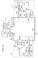
- Figure 5 is a schematic view of a particular embodiment of the monitoring system object of the invention.
- This system of Figure 5 is for monitoring a multi-wavelength ring array.
- This network is intended for the transmission, according to the HNS standard, of information in optical form, which is multiplexed in wavelength.
- an optical wavelength ⁇ 1 for example equal to 1549 nm
- an optical wavelength ⁇ 2 for example equal to 1541 nm
- the management means G and the multiplexers ME1 and ME2 exchange information with each other.
- Each of the multiplexers MO1 and M02 is intended to insert in the fiber F1 the information from the associated MIE and to extract from this fiber F1 the information intended for this associated MIE.
- Each multiplexer ME1 or ME2 is provided with an opto-electric converter OE1 or OE2 for converting into electrical form the information at the wavelength ⁇ 1 or ⁇ 2 which are extracted by the associated multiplexer MO1 or MO2.
- Each multiplexer ME1 or ME2 is also provided with a laser L1 or L2 intended to convert in optical form, at the wavelength ⁇ 1 or ⁇ 2, the information which comes from this multiplexer ME1 or ME2 and which must be inserted, thanks to to the associated multiplexer MO1 or MO2, among the non-extracted information.
- the network head T comprises two lasers LT1 and LT2 which emit respectively at the wavelengths ⁇ 1 and ⁇ 2 and which are controlled by the management means G.
- Each of these lasers LT1 and LT2 receives from the means G information (STM-1) in electrical form and converts this information in optical form.
- This information is sent to the fiber F1 via an optical coupler CO connected, on one side, to the outputs of the lasers LT1 and LT2 and, on the other side, to one end of the fiber F1.
- the network head T also comprises an optical demultiplexing means DM (for example a diffraction grating demultiplexer) which is connected on one side to the other end of the fiber F1 to receive the wavelength signals. ⁇ 1 and ⁇ 2 and, on the other side, an electrical multiplexing means MX.
- optical demultiplexing means DM for example a diffraction grating demultiplexer
- This multiplexing means MX is provided, at its input, with optoelectric conversion means (not shown) which receive the optical signals, of wavelengths ⁇ 1 and ⁇ 2, separated by the demultiplexing means DM, and convert these signals. in electric form.
- the multiplexing means MX communicates with the management means G in particular for transmitting to them the electrical signals multiplexed by this means MX.
- these oscillators OS1 and OS2 respectively modulate the associated lasers LT1 and LT2 by sinusoidal signals of low frequency.
- the superposition means MS comprise two sinusoidal electric oscillators of respective frequencies f1 and f2, which are respectively referenced OF1 and OF2 and associated with lasers L1 and L2.
- the oscillator OF1 (or OF2) modulates the associated laser L1 (or L2) by sinusoidal signals of low frequency f1 (or f2).
- the frequencies f1 and f2 are both chosen below the transmission band associated with the information to be transmitted in the network.
- broadband signals corresponding to this information are transmitted at a rate of 155 Mbits / s (STM1).
- Each coupler C1 or C2 is intended to take a small part of the overall optical power that reaches it via the fiber F1 (for example 5% of this power) for monitoring the ring network.
- Each monitoring circuit SC1 or SC2 provides information which is inserted in the STM-1 frame and which is thus recovered at the headend and processed by the management means G.
- the over-frequency modulation is detected in order to know whether the tracers (f1, f2) are present or absent at the input of each station.
- the coupler C1 or C2 is a coupler of the 5/95 type which passes 95% of the optical signals, which reaches it by via the fiber F1, to the multiplexer MO1 or MO2, which takes 5% of these signals for use in the corresponding monitoring circuit.
- the COE1 or COE2 converter is a photodiode that converts the optical signals (5%) from the coupler C1 or C2 into electrical signals.
- the low-pass filter PB1 or PB2, placed after the COE1 or COE2 converter is intended to eliminate all the high frequency portion of the signal, which is unnecessary for network monitoring.
- the automatic gain control device CG1 or CG2 receives the signals thus filtered and sends them to the two associated tone sensors DF11, DF12 or DF21, DF22 with a constant voltage level, regardless of the power level. at the entrance of the automatic gain control device.
- Each tone detector is an integrated circuit which is pre-set on one of the two frequencies f1 and f2 and which makes it possible to know if there is, at its input, presence or absence of an electrical signal at this frequency.
- the detectors DF11 and DF21 are both pre-set on the frequency f1 while the detectors DF12 and DF22 are both pre-set on the frequency f2.
- This presence or absence of frequency information is transferred, thanks to the corresponding control logic circuit CL1 or CL2, into a byte which is transmitted in the overhead of the signal sent to the head of the network T.
- the management means G read the bytes of overhead.
- the information developed for monitoring the ring network is thus centralized and allows network over-surveillance.
- F1-1 two voltage information is inserted in a F1 byte, denoted F1-1, and this information constitutes two bits B11 and B12 of F1-1.
- F1-2 two voltage information is inserted in a F1 byte, denoted F1-2, and this information constitutes two bits B21 and B22 of F1-2.
- the management means G make it possible to display the overheads of the information received by these means G and in particular the bytes F1.
- V1 V2, V3 and V4 that is to say the voltages Vs1 and Vs2 for each node N1 and N2.
- Table II below shows an example of an alarm truth table for a ring network of the kind shown in FIG. 5.
- the monitoring system according to the invention which is schematically shown in FIG. 6, also applies to the network shown in FIG. 5 and simply differs from the system according to the invention of FIG. 5 in that, in In the case of FIG. 6, the output of each control logic circuit CL1 or CL2 is not connected to the input interface I1 or I2 of the multiplexer ME1 or ME2 but to the sinusoidal oscillator OF12 or OF2 so as to modulating the carrier wave of frequency f1 or f2.
- the low-speed transmission channel is used which is associated, by over-modulation, with the broadband signal injected into the network.
- the photodetection means (not shown) which are placed at the input of the electrical multiplexing means MX of the headend T are followed by a bandpass filter (not shown) which takes the low-rate channels.
- FIG. 7 very schematically illustrates the monitoring of a unidirectional ring network at four nodes N1, N2, N3 and N4 according to the invention.
- the monitored network shown in FIG. 7 comprises a fiber F1 which goes from the headend T to return to this headend passing successively through the nodes N1 to N4.
- the section SF1 lies between the headend T and the node N1, the section SF2 between the nodes N1 and N2, the section SF3 between the nodes N2 and N3, the section SF4 between the nodes N3 and N4 and the section SF5 between node N4 and the headend.
- Wavelengths ⁇ 1, ⁇ 2, ⁇ 3 and ⁇ 4 are respectively assigned to the nodes N1, N2, N3 and N4.
- node N1 two sinusoidal electric oscillators (not shown) of respective frequencies f1 and f4 are used.
- node N2 two sinusoidal electric oscillators (not shown) of respective frequencies f2 and f1 are used.
- node N4 two sinusoidal electric oscillators (not shown) of respective frequencies f4 and f3 are used.
- the information to be transmitted by a ring network may be lost in certain cases, especially when the fiber F1 is cut off.
- FIG. 8 shows a bidirectional ring network with two nodes N1 and N2.
- FIG. 8 shows the network head T and the two nodes N1 and N2, to which the wavelengths ⁇ 1 and ⁇ 2 respectively are assigned, as well as the optical fiber F1 and an additional optical fiber F2 (spare fiber).
- the fibers F1 and F2 are traversed in opposite directions by the information.
- the node N1 comprises a double monitoring circuit composed of the elementary circuit CS1 and another elementary circuit CS1a constituted in the same way as the circuit CS1.
- the node N1 also comprises a double MIEO composed of the elementary multiplexer MO1 associated with the fiber F1 and another MIEO identical to the multiplexer MO1 but associated with the fiber F2 and referenced MO1a.
- the information is still taken on the fiber F1 by the coupler C1 and an additional coupler Cla, placed upstream of the multiplexer MO1a, can collect the information on the fiber F2 for the corresponding monitoring circuit CS1a.
- Oscillator OF1 modulates the two lasers L1 and L1a.
- node N2 which is only sketched in FIG. 8, is comparable to the structure of node N1.
- the coupler CO is connected to the two optical fibers F1 and F2.
- the demultiplexer DM of FIG. 5 is, in the case of FIG. 8, replaced by two demultiplexers of the DM demultiplexer type, which are referenced DM1 and DM2 and respectively connected to the fibers F1 and F2.
- the electric multiplexer MX of FIG. 5 is, in the case of FIG. 8, replaced by two electric multiplexers of the MX multiplexer type, which are referenced MX1 and MX2, are respectively connected to the demultiplexers DM1 and DM2 and communicate all two with the management means G.
- the signals coming from the two frequency detectors DF11 and DF12 are sent not only to the circuit CL1 but also to the circuit CL1a forming part of the elementary monitoring circuit CS1a associated with the fiber F2.
- the signals from the two frequency detectors DF11a and DF12a of the elementary circuit CS1a are sent not only to the associated control logic circuit CL1a but also to the control logic circuit CL1 of the elementary monitoring circuit CS1.
- sequences of the type B11, B12, B13, B14 are sent in the fibers F1 and F2.
- the bits 311, B12 come from the frequency detectors of the circuit CS1 and the bits B13, B14 come from the frequency detectors of the circuit CS1a.
- the network schematically represented in FIG. 9 comprises four nodes N1, N2, N3 and N4 connected by two optical fibers F1 and F2 which are traversed in opposite directions by the information circulating in the network in optical form.
- Each of the nodes includes an MIEO for inserting in both fibers the information that reaches him from an MIE also included in this node and to extract from these fibers the information for this node which are then sent to the MIE.
- the wavelengths ⁇ 1, ⁇ 2 and ⁇ 3 are processed in the node N1
- the wavelengths ⁇ 2 and ⁇ 4 are processed in the node N2
- the wavelengths ⁇ 3, ⁇ 4 and ⁇ 5 are processed in the node N3
- the wavelengths ⁇ 1 and ⁇ 5 are processed in the node N4.
- the nodes N1 and N4 communicate with each other by means of the length wavelength ⁇ 1 and the nodes N1 and N3 communicate with each other by means of the wavelength ⁇ 3.
- optical amplification at the nodes of a ring network.
- optical amplifier is used at a single wavelength, it is possible to realize a monitoring system according to the invention in which this optical amplifier is monitored as an optical transmitter.
- an additional surveillance point is provided in a surveillance system according to the invention to elaborate additional monitoring signals relating to this optical amplifier. .
- a monitoring system it is possible to develop, at each monitoring point, from the sampling of the frequency tracer, the signals functions of the tracer electrical power measurement, which allows a wavelength recognition, a measure of the level to reveal the signal degradation.
- a comparison with the noise level outside the useful tracer band makes it possible to elaborate the signal-to-noise ratio and to give information on the evolution of the signal-to-noise ratio of the broadband signal, relating to the "useful" information.
- a degradation observed on the tracer indicates a degradation also on the broadband signal.
- Figure 10 schematically illustrates an example of such a ring network with colored sections.
- the network of FIG. 10 comprises four nodes N1, N2, N3 and N4 and two optical fibers F1 and F2 traversed in opposite directions by the information to be transmitted in this bidirectional network.
- a wavelength is assigned to each section between two nodes of the network and four wavelengths ⁇ 1, ⁇ 2, ⁇ 3 and ⁇ 4 are used.
- the wavelength ⁇ 1 is assigned to the section between the nodes N1 and N2.
- the traffic exchanged between the node N1 and the node N2 borrows this wavelength ⁇ 1 on the short arc (fiber F1) and also on the long arc (fiber F2 intended to protect the network).
- monitoring of all wavelengths ⁇ 1 to ⁇ 4 is provided.
- the collected information makes it possible to elaborate the monitoring of the optical layer and any alarms are transmitted to the network management means. .
- the present invention is usable with other transmission standards such as the American standard SONET which is very close to the standard HNS.
Claims (9)
- System zur Überwachung eines Vielwellenlängen-Ringnetzes, welches Netz zum Übertragen von Informationen in optischer Form gemäß einer gegebenen Norm ausgelegt ist, die wellenlängen-multiplexiert sind, wobei diese Informationen, wenn sie in elektrischer Form umgewandelt sind, ein als Übertragungsband bezeichnetes Frequenzband besetzen, wobei dieses Netz umfasst:- Knoten (N1, N2; N1 bis N4), die optisch miteinander mittels wenigstens einer ersten optischen Faser (F1, F2) verbunden sind, die nacheinander durch diese Knoten verläuft und die dazu ausgelegt ist, in einer ersten Richtung von den Informationen durchlaufen zu werden,- elektronische Einfügungs-Extraktionsmultiplexer (ME1, ME2), genannt MIE, die jeweils in den Netzknoten angeordnet und dazu ausgelegt sind, Informationen zu anderen Knoten zu schicken,- optische Einfügungs-Extraktionsmultiplexer (MO1 M02, MO1a), genannt MIEO, die jeweils den MIE zugeordnet sind, wobei jeder MIEO dazu ausgelegt ist, in die erste Faser die vom zugeordneten MIE stammenden Informationen einzufügen und aus dieser ersten Faser die für diesen zugeordneten MIE bestimmten Informationen zu extrahieren, und- Mittel (G) zur Steuerung des Netzes, wobei wenigstens eine Wellenlänge in jedem Knoten verarbeitet wird, wobei dieses Überwachungssystem dadurch gekennzeichnet ist, dass es umfasst:- Mittel (OF1, OF2, OS1, OS2), um den Informationen in optischer Form bei einer gegebenen Wellenlänge pro Knoten ein optisches Überwachungssignal mit dieser gleichen Wellenlänge zu überlagern, wobei das Überwachungssignal dann, wenn dieses Signal in elektrische Form umgewandelt ist, eine Frequenz außerhalb des Übertragungsbands bezüglich der Informationen hat,- Mittel zum Schicken dieses Überwachungssignals zu den Knoten,- in jedem Knoten eine Überwachungsschaltung (CS1, CS1a, CS2), die dazu ausgelegt ist, wenigstens einen Teil eines optischen Überwachungssignals abzuzweigen, das zu diesem Knoten gelangt, Überwachungsinformationen als Funktion dieses abgezweigten Teils zu erstellen, und diese Überwachungsinformationen mittels des MIE und des MIEO dieses Knotens in die erste optische Faser zu schicken, wobei diese Überwachungsinformationen somit zu den Steuermitteln gelangen können.
- System nach Anspruch 1, dadurch gekennzeichnet, dass die Informationen gemäß der Übertragungsnorm der synchronen digitalen Hierarchie (Hierarchie Numérique Synchrone) übertragen werden.
- System nach Anspruch 2, dadurch gekennzeichnet, dass die Überwachungsinformationen an die Steuermittel (G) geschickt werden, nachdem sie in den in optischer Form zu übertragenden Informations-Überfluss eingefügt worden sind.
- System nach einem der Ansprüche 1 und 2, dadurch gekennzeichnet, dass jeder MIE eine Lichtemissionseinrichtung (L1, L1a, L2) umfasst, die optisch mit dem entsprechenden MIEO gekoppelt ist und die durch die elektrischen Signale gesteuert wird, die den in optischer Form zu übertragenden Informationen entsprechen, sowie durch ein elektrisches Signal, dessen Frequenz außerhalb des Übertragungsbands liegt, wobei dieses elektrische Signal durch elektrische Signale moduliert wird, die den Überwachungsinformationen entsprechen.
- System nach einem der Ansprüche 1 bis 4, dadurch gekennzeichnet, dass das Netz eine zweite optische Faser (F2) umfasst, die nacheinander durch die Knoten des Netzes verläuft und dazu ausgelegt ist, von den Informationen in einer der ersten Richtung entgegengesetzten zweiten Richtung durchlaufen zu werden, wobei jeder MIEO dazu ausgelegt ist, in die zweite Faser die vom zugeordneten MIE stammenden Informationen einzufügen und aus dieser zweiten Faser die für diesen zugeordneten MIE bestimmten Informationen zu extrahieren, und dass die in die erste Faser (F1) geschickten Überwachungsinformationen ebenfalls in die zweite Faser (F2) geschickt werden und umgekehrt.
- System nach einem der Ansprüche 1 bis 5, dadurch gekennzeichnet, dass jeder Knoten (N1, N2) einer Wellenlänge zugeordnet ist.
- System nach Anspruch 5, dadurch gekennzeichnet, dass das Netz ein Netz mit farbigen Knoten ist, wobei jeder Knoten dazu ausgelegt ist, eine Mehrzahl von Wellenlängen zu verarbeiten.
- System nach Anspruch 5, dadurch gekennzeichnet, dass das Netz ein Netz mit farbigen Abschnitten ist, wobei jeder Knoten dazu ausgelegt ist, zwei Wellenlängen zu verarbeiten.
- System nach einem der Ansprüche 1 bis 8, dadurch gekennzeichnet, dass die Frequenz jedes optischen Überwachungssignals, das in elektrische Form umgewandelt ist, unterhalb des Übertragungsbands liegt.
Applications Claiming Priority (2)
| Application Number | Priority Date | Filing Date | Title |
|---|---|---|---|
| FR9602262A FR2745453B1 (fr) | 1996-02-23 | 1996-02-23 | Systeme de surveillance d'un reseau en anneau multi-longueur d'onde |
| FR9602262 | 1996-02-23 |
Publications (2)
| Publication Number | Publication Date |
|---|---|
| EP0792038A1 EP0792038A1 (de) | 1997-08-27 |
| EP0792038B1 true EP0792038B1 (de) | 2006-06-07 |
Family
ID=9489511
Family Applications (1)
| Application Number | Title | Priority Date | Filing Date |
|---|---|---|---|
| EP97400379A Expired - Lifetime EP0792038B1 (de) | 1996-02-23 | 1997-02-20 | Überwachungssystem eines Multiwellenlängen-Ringnetzes |
Country Status (4)
| Country | Link |
|---|---|
| US (1) | US5943148A (de) |
| EP (1) | EP0792038B1 (de) |
| DE (1) | DE69736025T2 (de) |
| FR (1) | FR2745453B1 (de) |
Families Citing this family (17)
| Publication number | Priority date | Publication date | Assignee | Title |
|---|---|---|---|---|
| EP0876018A3 (de) * | 1997-02-21 | 2004-05-26 | Siemens Aktiengesellschaft | Verfahren und Anordnung zur Datanübertragung in einem Ringnetz |
| US5898801A (en) | 1998-01-29 | 1999-04-27 | Lockheed Martin Corporation | Optical transport system |
| IL137313A0 (en) * | 1998-02-04 | 2001-07-24 | Chromatis Networks Inc | Virtual network |
| FI980328A (fi) * | 1998-02-13 | 1999-08-14 | Nokia Networks Oy | Optinen tietoliikenneverkko |
| US7272321B1 (en) | 1999-05-10 | 2007-09-18 | Alloptic, Inc. | Passive optical network |
| US6687463B1 (en) | 1999-06-09 | 2004-02-03 | Alcatel Communications, Inc. | Communication system and method with optical banding |
| AU5600900A (en) * | 1999-06-09 | 2000-12-28 | Astral Point Communications, Inc. | Communication system and method with optical banding and optical management bus |
| US7386236B1 (en) | 1999-09-27 | 2008-06-10 | Alloptic, Inc. | Multiple wavelength TDMA optical network |
| US7158722B1 (en) * | 2000-07-13 | 2007-01-02 | At&T Corp. | Method for operating transparent node for WDM shared “virtual ring” networks |
| US20020101874A1 (en) * | 2000-11-21 | 2002-08-01 | Whittaker G. Allan | Physical layer transparent transport information encapsulation methods and systems |
| SE523986C2 (sv) * | 2001-03-09 | 2004-06-15 | Lumentis Ab | Optiskt WDM-Ringnät för flexibla förbindelser |
| SE524863C2 (sv) * | 2001-04-23 | 2004-10-12 | Transmode Systems Ab | Optiskt CWDM-system |
| US7206510B2 (en) * | 2001-10-09 | 2007-04-17 | Nippon Telegraph And Telephone Corporation | Ring network using multi-wavelength generator |
| CN100449964C (zh) * | 2001-12-31 | 2009-01-07 | 中兴通讯股份有限公司 | 对光同步数字传送体系的网络管理系统软件测试和故障定位的方法 |
| US6912339B2 (en) * | 2002-09-27 | 2005-06-28 | Lockheed Martin Corporation | Optical interface devices having balanced amplification |
| DE102005010610A1 (de) * | 2005-03-08 | 2006-09-21 | Siemens Ag | Optisches Übertragungssystem |
| US8228946B2 (en) | 2009-07-29 | 2012-07-24 | General Electric Company | Method for fail-safe communication |
Family Cites Families (8)
| Publication number | Priority date | Publication date | Assignee | Title |
|---|---|---|---|---|
| DE3525105A1 (de) * | 1985-07-13 | 1987-01-15 | Telefonbau & Normalzeit Gmbh | Verfahren und schaltungsanordnung zum rbertragen von informationen ueber eine rbertragungsstrecke |
| EP0234730B1 (de) * | 1986-02-11 | 1992-07-08 | MVS Incorporated | Multiplex-Analogsignalübertragung über Lichtwellenleiterkanal |
| US5150243A (en) * | 1989-06-12 | 1992-09-22 | Fujitsu Limited | Method and apparatus for monitoring an optical network interface |
| US5265096A (en) * | 1991-07-03 | 1993-11-23 | Transwitch Corporation | Sonet alarm indication signal transmission method and apparatus |
| KR970003527B1 (ko) * | 1994-05-14 | 1997-03-18 | 재단법인 한국전자통신연구소 | 파장분할 다중화 방식을 이용한 양방향 다채널 광 링 통신망 |
| US5513029A (en) * | 1994-06-16 | 1996-04-30 | Northern Telecom Limited | Method and apparatus for monitoring performance of optical transmission systems |
| FR2734437B1 (fr) * | 1995-05-17 | 1997-06-13 | Sutter Alain | Reseau en anneau de transmission d'informations multiplexees en longueur d'onde |
| FR2736777B1 (fr) * | 1995-07-12 | 1997-08-08 | Alcatel Nv | Reseau de transmission optique avec multiplexage de longueurs d'onde |
-
1996
- 1996-02-23 FR FR9602262A patent/FR2745453B1/fr not_active Expired - Fee Related
-
1997
- 1997-02-20 DE DE69736025T patent/DE69736025T2/de not_active Expired - Lifetime
- 1997-02-20 US US08/802,483 patent/US5943148A/en not_active Expired - Fee Related
- 1997-02-20 EP EP97400379A patent/EP0792038B1/de not_active Expired - Lifetime
Also Published As
| Publication number | Publication date |
|---|---|
| US5943148A (en) | 1999-08-24 |
| EP0792038A1 (de) | 1997-08-27 |
| FR2745453B1 (fr) | 1998-04-03 |
| FR2745453A1 (fr) | 1997-08-29 |
| DE69736025T2 (de) | 2006-12-21 |
| DE69736025D1 (de) | 2006-07-20 |
Similar Documents
| Publication | Publication Date | Title |
|---|---|---|
| EP0792038B1 (de) | Überwachungssystem eines Multiwellenlängen-Ringnetzes | |
| EP0677936B1 (de) | Wiederkonfigurierbares optisches Mehrwellenlängen-Ringnetzwerk | |
| EP0743772B1 (de) | Ringnetzwerk mit Wellenlängenmultiplexing zur Nachrichtenübertragung | |
| US9485050B2 (en) | Subchannel photonic routing, switching and protection with simplified upgrades of WDM optical networks | |
| US20130121685A1 (en) | Optical layer status exchange over osc - oam method for roadm networks | |
| US6141125A (en) | Intra-node diagnostic signal | |
| CN111224737B (zh) | 传输系统、传输装置和传输方法 | |
| FR2759834A1 (fr) | Reseau de transmission en anneau reconfigurable avec multiplexage en longueur d'onde pour liaisons semi-permanentes | |
| US6594047B1 (en) | Apparatus and method for providing optical channel overhead in optical transport networks | |
| US11451294B2 (en) | Method and system to prevent false restoration and protection in optical networks with a sliceable light source | |
| EP0812077A1 (de) | Endgerät für eine gesicherte bidirektionale, nach der synchronen digitalen Hierarchie multiplexierte Daten übermittelnde Verbindung | |
| EP1428333B1 (de) | Optisches ringnetzwerk mit doppeltem optischem bus | |
| US8842987B2 (en) | Security in multiwavelength optical networks | |
| EP0631405B1 (de) | WDM Zeitmultiplex-Schleifenübertragungssystem | |
| EP1355441A1 (de) | Verfahren unf Vorrichtung zum steuern der Übertragung optischer Signale | |
| JP3563588B2 (ja) | 光波長多重化装置の光出力レベル制御装置 | |
| EP2160045B1 (de) | Knoten zur Kommunikation von optischen Paketen | |
| US20080025237A1 (en) | Multiplex transmission apparatus, multiplex transmission system, and multiplex transmission method | |
| FR2770061A1 (fr) | Systeme de transmission de signal optique | |
| JP3776900B2 (ja) | 光波長多重化装置の光出力レベル制御装置 | |
| KR100330808B1 (ko) | 파장 분할 다중화 시스템에서 채널신호 국간 전송 유니트 | |
| JP2000278213A (ja) | 信号伝送システム | |
| EP1492380A1 (de) | Konfigurierbare, optische, signalverarbeitende Vorrichtung mit Breitbandquellen | |
| EP1098465A1 (de) | Verfahren zum Abführen von einem Kanal für ein optisches Wellenlängemultiplex-Übertragungsystem und Vorrichtung zur Anwendung dieses Verfahrens | |
| Sonnichsen et al. | Basic requirements and options for communication systems in scientific underwater cable networks |
Legal Events
| Date | Code | Title | Description |
|---|---|---|---|
| PUAI | Public reference made under article 153(3) epc to a published international application that has entered the european phase |
Free format text: ORIGINAL CODE: 0009012 |
|
| AK | Designated contracting states |
Kind code of ref document: A1 Designated state(s): DE GB IT |
|
| 17P | Request for examination filed |
Effective date: 19980130 |
|
| 17Q | First examination report despatched |
Effective date: 20030513 |
|
| GRAP | Despatch of communication of intention to grant a patent |
Free format text: ORIGINAL CODE: EPIDOSNIGR1 |
|
| GRAS | Grant fee paid |
Free format text: ORIGINAL CODE: EPIDOSNIGR3 |
|
| GRAA | (expected) grant |
Free format text: ORIGINAL CODE: 0009210 |
|
| AK | Designated contracting states |
Kind code of ref document: B1 Designated state(s): DE GB IT |
|
| PG25 | Lapsed in a contracting state [announced via postgrant information from national office to epo] |
Ref country code: IT Free format text: LAPSE BECAUSE OF FAILURE TO SUBMIT A TRANSLATION OF THE DESCRIPTION OR TO PAY THE FEE WITHIN THE PRE;WARNING: LAPSES OF ITALIAN PATENTS WITH EFFECTIVE DATE BEFORE 2007 MAY HAVE OCCURRED AT ANY TIME BEFORE 2007. THE CORRECT EFFECTIVE DATE MAY BE DIFFERENT FROM THE ONE RECORDED.SCRIBED TIME-LIMIT Effective date: 20060607 |
|
| REG | Reference to a national code |
Ref country code: GB Ref legal event code: FG4D Free format text: NOT ENGLISH |
|
| REF | Corresponds to: |
Ref document number: 69736025 Country of ref document: DE Date of ref document: 20060720 Kind code of ref document: P |
|
| GBT | Gb: translation of ep patent filed (gb section 77(6)(a)/1977) |
Effective date: 20060906 |
|
| PLBE | No opposition filed within time limit |
Free format text: ORIGINAL CODE: 0009261 |
|
| STAA | Information on the status of an ep patent application or granted ep patent |
Free format text: STATUS: NO OPPOSITION FILED WITHIN TIME LIMIT |
|
| 26N | No opposition filed |
Effective date: 20070308 |
|
| PGFP | Annual fee paid to national office [announced via postgrant information from national office to epo] |
Ref country code: IT Payment date: 20080213 Year of fee payment: 12 |
|
| PG25 | Lapsed in a contracting state [announced via postgrant information from national office to epo] |
Ref country code: IT Free format text: LAPSE BECAUSE OF NON-PAYMENT OF DUE FEES Effective date: 20090220 |
|
| PGFP | Annual fee paid to national office [announced via postgrant information from national office to epo] |
Ref country code: DE Payment date: 20120229 Year of fee payment: 16 |
|
| PGFP | Annual fee paid to national office [announced via postgrant information from national office to epo] |
Ref country code: GB Payment date: 20120127 Year of fee payment: 16 |
|
| GBPC | Gb: european patent ceased through non-payment of renewal fee |
Effective date: 20130220 |
|
| REG | Reference to a national code |
Ref country code: DE Ref legal event code: R119 Ref document number: 69736025 Country of ref document: DE Effective date: 20130903 |
|
| PG25 | Lapsed in a contracting state [announced via postgrant information from national office to epo] |
Ref country code: DE Free format text: LAPSE BECAUSE OF NON-PAYMENT OF DUE FEES Effective date: 20130903 Ref country code: GB Free format text: LAPSE BECAUSE OF NON-PAYMENT OF DUE FEES Effective date: 20130220 |