EP2160045B1 - Knoten zur Kommunikation von optischen Paketen - Google Patents
Knoten zur Kommunikation von optischen Paketen Download PDFInfo
- Publication number
- EP2160045B1 EP2160045B1 EP09167359A EP09167359A EP2160045B1 EP 2160045 B1 EP2160045 B1 EP 2160045B1 EP 09167359 A EP09167359 A EP 09167359A EP 09167359 A EP09167359 A EP 09167359A EP 2160045 B1 EP2160045 B1 EP 2160045B1
- Authority
- EP
- European Patent Office
- Prior art keywords
- optical
- channels
- packets
- output
- wavelength
- Prior art date
- Legal status (The legal status is an assumption and is not a legal conclusion. Google has not performed a legal analysis and makes no representation as to the accuracy of the status listed.)
- Active
Links
Images


Classifications
-
- H—ELECTRICITY
- H04—ELECTRIC COMMUNICATION TECHNIQUE
- H04Q—SELECTING
- H04Q11/00—Selecting arrangements for multiplex systems
- H04Q11/0001—Selecting arrangements for multiplex systems using optical switching
- H04Q11/0005—Switch and router aspects
-
- H—ELECTRICITY
- H04—ELECTRIC COMMUNICATION TECHNIQUE
- H04J—MULTIPLEX COMMUNICATION
- H04J14/00—Optical multiplex systems
- H04J14/02—Wavelength-division multiplex systems
- H04J14/0201—Add-and-drop multiplexing
- H04J14/0202—Arrangements therefor
- H04J14/0204—Broadcast and select arrangements, e.g. with an optical splitter at the input before adding or dropping
-
- H—ELECTRICITY
- H04—ELECTRIC COMMUNICATION TECHNIQUE
- H04J—MULTIPLEX COMMUNICATION
- H04J14/00—Optical multiplex systems
- H04J14/02—Wavelength-division multiplex systems
- H04J14/0201—Add-and-drop multiplexing
- H04J14/0202—Arrangements therefor
- H04J14/0205—Select and combine arrangements, e.g. with an optical combiner at the output after adding or dropping
-
- H—ELECTRICITY
- H04—ELECTRIC COMMUNICATION TECHNIQUE
- H04J—MULTIPLEX COMMUNICATION
- H04J14/00—Optical multiplex systems
- H04J14/02—Wavelength-division multiplex systems
- H04J14/0201—Add-and-drop multiplexing
- H04J14/0202—Arrangements therefor
- H04J14/0209—Multi-stage arrangements, e.g. by cascading multiplexers or demultiplexers
-
- H—ELECTRICITY
- H04—ELECTRIC COMMUNICATION TECHNIQUE
- H04J—MULTIPLEX COMMUNICATION
- H04J14/00—Optical multiplex systems
- H04J14/02—Wavelength-division multiplex systems
- H04J14/0201—Add-and-drop multiplexing
- H04J14/0202—Arrangements therefor
- H04J14/021—Reconfigurable arrangements, e.g. reconfigurable optical add/drop multiplexers [ROADM] or tunable optical add/drop multiplexers [TOADM]
- H04J14/0212—Reconfigurable arrangements, e.g. reconfigurable optical add/drop multiplexers [ROADM] or tunable optical add/drop multiplexers [TOADM] using optical switches or wavelength selective switches [WSS]
-
- H—ELECTRICITY
- H04—ELECTRIC COMMUNICATION TECHNIQUE
- H04J—MULTIPLEX COMMUNICATION
- H04J14/00—Optical multiplex systems
- H04J14/02—Wavelength-division multiplex systems
- H04J14/0201—Add-and-drop multiplexing
- H04J14/0202—Arrangements therefor
- H04J14/0213—Groups of channels or wave bands arrangements
-
- H—ELECTRICITY
- H04—ELECTRIC COMMUNICATION TECHNIQUE
- H04J—MULTIPLEX COMMUNICATION
- H04J14/00—Optical multiplex systems
- H04J14/02—Wavelength-division multiplex systems
- H04J14/0201—Add-and-drop multiplexing
- H04J14/0215—Architecture aspects
- H04J14/0217—Multi-degree architectures, e.g. having a connection degree greater than two
-
- H—ELECTRICITY
- H04—ELECTRIC COMMUNICATION TECHNIQUE
- H04J—MULTIPLEX COMMUNICATION
- H04J14/00—Optical multiplex systems
- H04J14/02—Wavelength-division multiplex systems
- H04J14/0221—Power control, e.g. to keep the total optical power constant
-
- H—ELECTRICITY
- H04—ELECTRIC COMMUNICATION TECHNIQUE
- H04J—MULTIPLEX COMMUNICATION
- H04J14/00—Optical multiplex systems
- H04J14/02—Wavelength-division multiplex systems
- H04J14/0227—Operation, administration, maintenance or provisioning [OAMP] of WDM networks, e.g. media access, routing or wavelength allocation
- H04J14/0241—Wavelength allocation for communications one-to-one, e.g. unicasting wavelengths
- H04J14/0242—Wavelength allocation for communications one-to-one, e.g. unicasting wavelengths in WDM-PON
- H04J14/0245—Wavelength allocation for communications one-to-one, e.g. unicasting wavelengths in WDM-PON for downstream transmission, e.g. optical line terminal [OLT] to ONU
- H04J14/0246—Wavelength allocation for communications one-to-one, e.g. unicasting wavelengths in WDM-PON for downstream transmission, e.g. optical line terminal [OLT] to ONU using one wavelength per ONU
-
- H—ELECTRICITY
- H04—ELECTRIC COMMUNICATION TECHNIQUE
- H04J—MULTIPLEX COMMUNICATION
- H04J14/00—Optical multiplex systems
- H04J14/02—Wavelength-division multiplex systems
- H04J14/0227—Operation, administration, maintenance or provisioning [OAMP] of WDM networks, e.g. media access, routing or wavelength allocation
- H04J14/0241—Wavelength allocation for communications one-to-one, e.g. unicasting wavelengths
- H04J14/0242—Wavelength allocation for communications one-to-one, e.g. unicasting wavelengths in WDM-PON
- H04J14/0249—Wavelength allocation for communications one-to-one, e.g. unicasting wavelengths in WDM-PON for upstream transmission, e.g. ONU-to-OLT or ONU-to-ONU
- H04J14/025—Wavelength allocation for communications one-to-one, e.g. unicasting wavelengths in WDM-PON for upstream transmission, e.g. ONU-to-OLT or ONU-to-ONU using one wavelength per ONU, e.g. for transmissions from-ONU-to-OLT or from-ONU-to-ONU
-
- H—ELECTRICITY
- H04—ELECTRIC COMMUNICATION TECHNIQUE
- H04J—MULTIPLEX COMMUNICATION
- H04J14/00—Optical multiplex systems
- H04J14/02—Wavelength-division multiplex systems
- H04J14/0227—Operation, administration, maintenance or provisioning [OAMP] of WDM networks, e.g. media access, routing or wavelength allocation
- H04J14/0254—Optical medium access
- H04J14/0272—Transmission of OAMP information
- H04J14/0275—Transmission of OAMP information using an optical service channel
-
- H—ELECTRICITY
- H04—ELECTRIC COMMUNICATION TECHNIQUE
- H04J—MULTIPLEX COMMUNICATION
- H04J14/00—Optical multiplex systems
- H04J14/02—Wavelength-division multiplex systems
- H04J14/0278—WDM optical network architectures
- H04J14/0283—WDM ring architectures
-
- H—ELECTRICITY
- H04—ELECTRIC COMMUNICATION TECHNIQUE
- H04J—MULTIPLEX COMMUNICATION
- H04J14/00—Optical multiplex systems
- H04J14/02—Wavelength-division multiplex systems
- H04J14/0278—WDM optical network architectures
- H04J14/0284—WDM mesh architectures
-
- H—ELECTRICITY
- H04—ELECTRIC COMMUNICATION TECHNIQUE
- H04J—MULTIPLEX COMMUNICATION
- H04J14/00—Optical multiplex systems
- H04J14/02—Wavelength-division multiplex systems
- H04J14/0278—WDM optical network architectures
- H04J14/0286—WDM hierarchical architectures
-
- H—ELECTRICITY
- H04—ELECTRIC COMMUNICATION TECHNIQUE
- H04Q—SELECTING
- H04Q11/00—Selecting arrangements for multiplex systems
- H04Q11/0001—Selecting arrangements for multiplex systems using optical switching
- H04Q11/0005—Switch and router aspects
- H04Q2011/0007—Construction
- H04Q2011/0013—Construction using gating amplifiers
-
- H—ELECTRICITY
- H04—ELECTRIC COMMUNICATION TECHNIQUE
- H04Q—SELECTING
- H04Q11/00—Selecting arrangements for multiplex systems
- H04Q11/0001—Selecting arrangements for multiplex systems using optical switching
- H04Q11/0005—Switch and router aspects
- H04Q2011/0007—Construction
- H04Q2011/0015—Construction using splitting combining
-
- H—ELECTRICITY
- H04—ELECTRIC COMMUNICATION TECHNIQUE
- H04Q—SELECTING
- H04Q11/00—Selecting arrangements for multiplex systems
- H04Q11/0001—Selecting arrangements for multiplex systems using optical switching
- H04Q11/0005—Switch and router aspects
- H04Q2011/0007—Construction
- H04Q2011/0016—Construction using wavelength multiplexing or demultiplexing
-
- H—ELECTRICITY
- H04—ELECTRIC COMMUNICATION TECHNIQUE
- H04Q—SELECTING
- H04Q11/00—Selecting arrangements for multiplex systems
- H04Q11/0001—Selecting arrangements for multiplex systems using optical switching
- H04Q11/0005—Switch and router aspects
- H04Q2011/0037—Operation
- H04Q2011/0039—Electrical control
Definitions
- the present invention relates to Wavelength Division Multiplexing (WDM) spectral multiplexing optical communications networks.
- WDM Wavelength Division Multiplexing
- the invention relates to a node architecture capable of inserting, extracting and transferring optical packets transported over wavelength channels, in particular multi-channel optical packets.
- Known WDM network nodes are capable of inserting, extracting and transferring optical packets carried on wavelength channels received on an input.
- WO 01/061903 A1 discloses a node inserted between an input fiber and an output fiber carrying wavelength channels. This node offers Traffic Insertion, Traffic Extraction and Traffic Transfer Functions. These functions are performed on traffic transported by wavelength channels. By performing the transfer function in a transparent manner, ie without converting the data signal to the electronic domain, the number of necessary optical transponders is reduced with respect to a switching node producing an electronic conversion of all incoming traffic. .
- An object of the invention is to provide an optical packet switching node having a higher degree of connectivity than in the known art, that is to say comprising for example several input fibers and one or more output fibers. .
- Such a node must be able for example to switch traffic in a mesh network or networks of multiple rings.
- optical packet switching node offering globally, in the optical domain, the same functionality as an electronic router.
- the object of the invention is in particular to satisfy one or more of these needs.
- At least one of said wavelength channel splitters is capable of separating on at least one packet output, at least one wavelength channel carrying data packets, and on at least one other output, called output for optical circuits, at least one wavelength channel carrying an optical circuit, said data packets and said optical circuit being intended for the same output of the switching node, said node having a circuit transfer optical path connecting an optical circuit input of the wavelength channel combiner disposed on said node output to said optical circuit output of said at least one respective wavelength channel splitter and that the combiner is able to pass optical packets on said wavelength channel received on a packet input from a respective insertion optical path to said optical packet switching node output. and at least one optical circuit on a wavelength channel received on an optical circuit input of said wavelength channel combiner from a respective optical circuit transfer path.
- the optical packet switching node preferably has an insertion module capable of generating multi-channel optical packets on a plurality of wavelength channels, a multi-channel optical packet being insertable on the optical insertion path. respective.
- the optical packet switching node may use a periodic demultiplexer type separator.
- the optical packet switching node has, according to one embodiment of the invention, at least one separator which is an adjustable demultiplexer.
- the optical packet switching node is such that said at least one adjustable demultiplexer can be configured to separate on a packet output at least one wavelength channel when it carries optical packets and to separate said at least one wavelength channel on a circuit output, when said at least one wavelength channel carries an optical circuit.
- the optical packet switching node may also be such that at least one of said insertion modules comprises at least two optical packet transmitters, each capable of inserting optical packets on a channel of different wavelength, and that at least one of the separators is capable of separating, on the same packet splitter output, said two channels of different wavelengths
- the optical packet switching node may use a periodic multiplexer type combiner.
- the optical packet switching node may also use an adjustable multiplexer type combiner.
- the optical packet switching node is such that at least one of said insertion modules comprises a wavelength tunable packet transmitter.
- the switching node according to one embodiment of the invention can be advantageously used when the packets received at its inputs are multi-channel optical packets.
- optical packet switching node can share its extraction and transfer resources between optical packet traffic that it is able to receive on several inputs.
- the node is reconfigurable, that is to say modifies the allocation of the packet and circuit switching resources, for example when the nature of the protocols (packets or circuits) on the channels wavelengths received on each of the inputs changes over time, or that varies the relative priority of these traffic, or that still vary, if the node has several outputs, the outputs of the node on which these traffic must exit.
- This reconfigurability of the node is an advantage for solving the general problem of designing flexible optical networks, ie whose end-to-end connections on each wavelength channel are easily reconfigurable, particularly when these channels carry packets. optics.
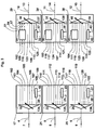
- the switching node 1 is part of a network comprising other nodes 2, the nodes 2 being interconnected by optical links 3, for example optical fibers.
- the links 3 carry optical circuits or optical packets or both on wavelength channels.
- Node 1 is connected to three nodes 2 upstream in the network by optical links 7, 8, 9, for example optical fibers, respectively coupled to its inputs 4, 5, 6.
- the node 1 is connected to three nodes 2 downstream in the network by optical links 13, 14, 15, for example optical fibers, respectively coupled to the outputs 10, 11, 12 of the node 1.
- the figure 1 present a state at a given instant, where the links 7, 8 and 9 carry optical circuits on wavelength channels, on 12 channels of wavelengths ⁇ 13 to ⁇ 24 .
- the data on each of these channels are carried for example according to the standards of SONET or SDH protocols or any other optical circuit protocols.
- the optical circuit protocols carried by the channels ⁇ 13 to ⁇ 24 are not necessarily identical.
- the input 4 receives the channels ⁇ 13 to ⁇ 16
- the input 5 receives the channels ⁇ 17 to ⁇ 20
- the input 6 receives the channels ⁇ 21 to ⁇ 24 .
- the figure 1 also presents, at the same time, 12 channels of wavelengths ⁇ 1 to ⁇ 12 , carrying optical packets on wavelength channels.
- the input 4 receives the channels ⁇ 1 to ⁇ 4
- the input 5 receives the channels ⁇ 5 to ⁇ 8
- the input 6 receives the channels ⁇ 9 to ⁇ 12 .
- the wavelength channels ⁇ 1 to ⁇ 24 belong to a predetermined grid of 24 wavelength channels.
- the positive integer of these channels could be different, for example equal to 40 or 80 channels.
- the data rate per wavelength channel is set by the rate of the optical modulators of the nodes of the optical network, for example 10 or 40 Gbit / s. Channels do not necessarily carry signals at the same rates.
- the wavelength channels ⁇ 1 to ⁇ 24 are all different.
- the network node does not have to solve a problem of contention between channels of wavelengths, this problem being assumed set elsewhere in the network.
- wavelength channels ⁇ 4c , ⁇ 5c , ⁇ 6c carry signaling information relating to the optical packets and the optical circuits. These six channels are supposed to be all different from the channels ⁇ 1 to ⁇ 24 , thus ensuring an "out of band" signaling of the traffic carried by the channels ⁇ 1 to ⁇ 24 .
- an embodiment of the invention could however also be presented, using an "in band” signaling for one or more traffics.
- the uncle length ⁇ 1 could have carried "in band” the signaling information of the optical packets that it carries on the optical link 7, at the moment represented on the figure 1 .
- the signaling channels ⁇ 4c , ⁇ 5c , ⁇ 6c , ⁇ 10c , ⁇ 11c , ⁇ 12c are at each instant distinct from each of the channels ⁇ 1 to ⁇ 24 .
- the figure 1 also schematically represents an optical circuit transceiver terminal 16 connected to the switching node 1 by optical links 105, 112, 119, 123, 124 and 125, for example optical fibers.
- the links 105, 112, 119 carry optical circuits on the channels ⁇ 17 , ⁇ 21 and ⁇ 22 , these circuits corresponding to traffic extracted from the node 1 to the terminal 16.
- the links 123, 124 and 125 carry circuits on the same channels ⁇ 17 , ⁇ 21 and ⁇ 22 , these circuits corresponding to traffic inserted from the terminal 16 to the node 1.
- the channel ⁇ 17 is extracted from the node 1 by the link 119.
- the data it carries is demodulated at the terminal 16.
- an exchange of information encoded on bits, and corresponding to an extraction and / or insertion of traffic is performed.
- a transmitter is used to modulate bits inserted on one or more wavelength channels.
- the channel ⁇ 17 is reinserted in the node 1 by the fiber 125, then transmitted to the output 10.
- the operation is similar for the channels ⁇ 21 and ⁇ 22 , at the transceiver terminal 16.
- the circuit on the channel ⁇ 24 is only transferred from the input 6 to the output 12, without traffic exchange at the terminal 16.
- all the channels ⁇ 13 to ⁇ 24 are therefore directly transferred to one of the outputs of node 1, with the exception of the channels ⁇ 17 , ⁇ 21 and ⁇ 22 .
- the node 1 in the two embodiments presented has the accessory capacity, collaborating with the terminal 6, to perform the insertion, extraction and transfer of optical circuits on wavelength channels. As will be explained in more detail with the following figures, the node 1 in the two embodiments presented has the main capacity to achieve the insertion, extraction and transfer of optical packets carried by channels of lengths d wave.
- the channels ⁇ 1 to ⁇ 4 received at the inputs 4 of the node 1 and which carry optical packets are directed towards the output 10, via the module 31 ( figure 2 ) associated with the output 10.
- the module 31 is capable of performing insertion, extraction or transfer of optical packets on each of the channels ⁇ 1 to ⁇ 4 .
- the channels ⁇ 5 to ⁇ 8 received on the input 5 and carrying optical packets are also directed towards the output 10, via the module 31.
- the module 31 is capable of insertion, extraction and transfer of optical packets on the channels ⁇ 5 to ⁇ 8 .
- the distribution of the wavelength channels represented on the figure 1 at the outputs 10, 11 and 12, corresponds to an illustration at a given moment, according to the signaling information received by the node 1 on the channels ⁇ 4c , ⁇ 5c and ⁇ 6c . This distribution may change over time.
- the WDM network of figure 1 is preferably designed so that any node can communicate with any other node in the optical domain.
- the node 1 according to the first and the second embodiment can carry transparently packets data over wavelength channels from its inputs to its outputs.
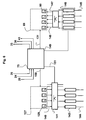
- the figure 2 schematically represents the optical plane of the node 1, including its connections to the terminal 16.
- Each of the inputs 4, 5 and 6 is connected to the input of a respective separator 18, 22, 26, these separators being able to separate on their respective outputs of the wavelength channels.
- Each of the outputs 10, 11 and 12 is connected to the output of a respective combiner 30, 35 and 40, these combiners being able to pass wavelength channels from their respective inputs to their respective outputs.
- Signaling detectors 19, 23 and 27 associated with the respective separators 18, 22 and 26 are capable of demodulating data received on the signaling channels ⁇ 4c , ⁇ 5c , ⁇ 6c ( figure 1 ) respectively received on the inputs 4, 5 and 6.
- Signaling transmitters 32, 37 and 42 associated are capable of modulating data on the signaling channels ⁇ 10c , ⁇ 11c , ⁇ 12c that the respective combiners 30, 35 and 40 pass to the respective outlets 10, 11 and 12.
- the signaling detectors 19, 23 and 27 are coupled to a respective output of a respective separator 18, 22 and 26 by a respective optical link 134, 135 and 136, for example an optical fiber.
- each signaling transmitter 32, 37 and 42 is coupled to an input of a respective combiner 30, 35 and 40 by a respective optical link 137, 138 and 139, for example an optical fiber.
- the combiners 30, 35 and 40 are connected to respective packet switching modules 31, 36 and 41 which are capable of extracting, inserting and transferring optical packets carried by optical channels.
- the combiner 30 is connected to the respective module 31 by the respective optical insertion paths 52, 55 and 58. Similar optical insertion paths make it possible to connect the combiners 35 and 40 to the respective modules 36 and 41.
- modules 31, 36 and 41 are connected to each of the separators 18, 22 and 26 by packet extraction paths, for example optical fibers.
- the outputs of the separators 18, 22 and 26 and the respective inputs of the packet switching modules 31, 36, 41 or combiners 30, 35 and 40 are numbered. These inputs and outputs bear the same numbers when they are connected. by an optical path. So, on the figure 3 , the output 102 of the separator 18 is connected by a not shown optical path, for example an optical fiber, to the input 102 of the packet switching module 31.
- the optical path (not shown on the figure 3 ) connecting a splitter output and a packet switching module or combiner input to the same digit.
- the path 102 will be the one that connects the output 102 of the splitter 18 to the input 102 of the switching module 31.
- the path 106 has been indicated on the figure 2 . As will be seen below, this path 106 directly connects the output 106 of the separator 18 to the input 106 of the combiner 30, to perform the transfer of channels carrying optical circuits.
- the separator outputs to packet extraction paths at the same number are numbered 102,103 and 104 for the separator 18, 109, 110 and 111 for the separator 22 and 116, 117 and 118 for the separator 26.
- Each of the separators 18, 22 and 26 has three packet outputs respectively connected to the three modules 31, 36 and 41.
- the optical paths 102, 103 and 104 connect three outputs of the splitter 18 respectively to an input of the module 31, an input of the module 36 and a input module 41.
- the separators 22 and 26 are numbered 102,103 and 104 for the separator 18, 109, 110 and 111 for the separator 22 and 116, 117 and 118 for the separator 26.
- Each of the separators 18, 22 and 26 has three packet outputs respectively connected to the three modules 31, 36 and 41.
- the optical paths 102, 103 and 104 connect three outputs of the splitter 18 respectively to an input of the module 31, an input of the module 36 and a input module 41.
- the circuit extraction paths 105, 112 and 119 are connected to three circuit extraction outputs, at the same numbers, respectively belonging to the separators 18, 22 and 26. These paths 105, 112 and 119 terminate at the terminal 16. as seen previously ( figure 2 ).
- the circuit insertion paths 123, 124 and 125 are connected to three circuit insertion inputs, at the same reference numerals, belonging to the three respective combiners 30, 35 and 40. These paths 123, 124 and 125 also terminate. at the terminal 16.
- Node 1 ( figure 2 ) also comprises nine optical paths, for example optical fibers, directly connecting separator outputs to inputs of the combiners for transferring optical circuits.
- the splitter outputs and combiner inputs associated with these paths are numbered at the same number on the figure 3 .
- the three circuit transfer outputs 106, 107 and 108 of the separator 18 are connected to the three circuit transfer inputs 106, 107 and 108 respectively belonging to the combiners 30, 35 and 40.
- the three circuit transfer outputs 113, 114 and 115 of the separator 22 are connected to the three circuit transfer inputs 113, 114 and 115 respectively belonging to the combiners 30, 35 and 40.
- the three circuit transfer outputs 120, 121 and 122 of the separator 26 are connected to the three transfer inputs of circuits 120, 121 and 122 respectively belonging to the combiners 30, 35 and 40.
- Separator output Type of transport Switching capacity Module crossed (1) Release node 102 package extraction, insertion or transfer 31 10 103 package extraction, insertion or transfer 36 11 104 package extraction, insertion or transfer 41 12 105 circuit extraction no To the terminal 16 (2) 106 circuit transfer no 10 107 circuit transfer no 11 108 circuit transfer no 12 109 package extraction, insertion or transfer 31 10 110 package extraction, insertion or transfer 36 11 111 package extraction, insertion or transfer 41 12 112 circuit extraction no To terminal 16 (2) 113 circuit transfer no 10 114 circuit transfer no 11 115 circuit transfer no 12 116 package extraction, insertion or transfer 31 10 117 package extraction, insertion or transfer 36 11 118 package extraction, insertion or transfer 41 12 119 circuit extraction no To the terminal 16 (2) 120 circuit transfer no 10 121 circuit transfer no 11 122 circuit transfer no
- the correspondences defined by the preceding table are stable over time, even if the wavelength channels received at the inputs 4,5 and 6 or leaving the outputs 10,11 and 12 evolve over time, as well as the type of traffic carried by these channels (circuits or packets).
- a splitter and an associated signaling receiver are each united on a respective optical card 17, 21 and 25.
- a combiner, an associated packet switching module and an associated signaling transmitter are each assembled on an optical card 29, 34 and 39.
- the optical paths of circuits 105, 106, 107, 108, 112, 113, 114, 115, 119, 120, 121, 122, 123, 124 and 125 may be free optical fibers but their crossing can be advantageously ordered by partially integrating these fibers into an organic flexible sheet 44.
- the optical paths of packets 102, 103, 104, 109, 110, 111, 116, 117 and 118 may be free fibers but their crossing may advantageously being ordered by partially integrating these fibers into an organic flexible sheet 45.
- the figure 4 schematically represents a detailed view of the packet switching module 31 of the figure 2 .
- Modules 36 and 41 ( figure 2 ) are in the first embodiment shown, identical to the module 31.
- the module 31 includes a respective star coupler 46, type 3: 4.
- the three inputs 102, 109, 116 of the coupler 46 are coupled by extraction optical paths to the same numbers, to separator outputs with the same numbers ( figure 4 ). Its three outputs 50, 53, 56 are coupled at the head of three respective optical insertion paths 52, 55 and 58, for example optical fibers. The respective ends of these transfer paths are coupled to three inputs 51, 54 and 57 of the respective combiner ( figures 3 and 4 ).
- Each of the three paths 52, 55 and 58 comprises a respective optical gate 59, 60 and 61 and a respective insertion coupler 62, 63 and 64.
- the optical gates are for example semiconductor amplifiers.
- the insertion couplers are 2: 1 couplers, for example of the optical fiber type. Other types of optical doors or insertion couplers are possible.
- each coupler 62, 63 and 64 are on the respective insertion paths 52, 55 and 58.
- the insertion couplers 62, 63 and 64 are on the respective optical insertion paths, between the respective optical gates 59, 60 and 61 and the respective combiner inputs 51, 54 and 57.
- Each insertion optical path 52, 55 and 58 may comprise an optical delay line 133 between the respective outputs of the star coupler 50, 53 and 56 and the respective optical gates 59, 60 and 61.
- the respective delay lines 133 when present, for example lengths of optical fibers, make it possible to adjust the transit time of the packets through the node 1 of the figure 1 .
- the other output 132 of the star coupler 46 is connected by another optical packet extraction path 130, for example an optical fiber, to the input of the optical packet extraction module 127.
- the input 127 is coupled at the input of the demultiplexer 128 capable of separating the twelve channels ⁇ 1 to ⁇ 12 on each of its twelve outputs, thus obtaining a different channel on each of its outputs.
- These twelve channels can be received by twelve optical packet receivers 129, capable of demodulating optical packets carried by the wavelength channels ⁇ 1 to ⁇ 12 .
- An optical packet receiver 129 (also known as the "burst mode receiver") is capable of demodulating the data of the successive optical packets by adapting to the signal level of each packet, which can vary according to the origin of the optical packet and the distance it has traveled in the network.
- the packet receivers 129 also perform clock recovery.
- each of the three insertion modules 66, 69 and 72 is capable, by means of four optical packet transmitters 80, of transmitting on four channels.
- the module 66 is capable of transmitting on the channels ⁇ 1 to ⁇ 4.
- the module 69 is capable of transmitting on the channels ⁇ 5 to ⁇ 8 .
- the module 72 is capable of transmitting on the channels ⁇ 9 to ⁇ 12 .
- the twelve channels of wavelengths ⁇ 1 to ⁇ 12 accessible through the three insertion modules 66, 69 and 72 are therefore identical to the twelve wavelength channels that can be demodulated. 129.
- Each of the insertion modules 66, 69 and 72 comprises a respective channel combiner 79 for passing from the respective inputs 81 of these combiners to respective optical links 67, 70 and 73, for example optical fibers. , the wavelength channels emitted by the groups of four respective optical packet transmitters 80.
- the fiber 67 is capable of guiding the channels ⁇ 1 to ⁇ 4 from the output 65 of the insertion module 66 to the second input of the coupler 62.
- the fiber 70 is capable of guiding the channels ⁇ 5 to ⁇ 8 from the output 68 of the insertion module 69 to the second input of the coupler 63.
- the fiber 73 is capable of guiding the channels ⁇ 9 to ⁇ 12 from the output 71 of the insertion module 72 to the second input of the coupler 64.
- the combiner 79 may for example be of the Arrayed Waveguide Grating or AWG type on silica on silicon or a multiplexer using fibers carrying photo-refractive diffraction gratings (Fiber Bragg Gratings or FBGs) or a multiplexer. optical volume, ie not using optical guidance, other types of technologies are possible. Each combiner 79 may also be a 4: 1 optical coupler (agnostic at the wavelength channels) based on optical fibers or in planar silica-on-silicon or optical volume technology, other types of coupler technologies being possible. .
- the combiner 79 may also be made of GaInAsP / InP semiconductor material, for example if the channels ⁇ 1 to ⁇ 12 are around 1.55 ⁇ m.
- the combiner 79 as well as the optical packet transmitters 80 can also be integrated monolithically in GaInAsP / InP technologies on the same InP substrate.
- the separators 18, 22 and 26 are adjustable demultiplexers, each having one input and eight outputs. Each of these three separators is capable of separating on each of seven of its eight outputs, and under the control of the controller 75 by the links 76, any combination of the channels ⁇ 1 to ⁇ 24 . Each of the separators 18, 22 and 26 is also capable of separating on its eighth respective output the respective signaling channels ⁇ 4c , ⁇ 5c , ⁇ 6c ( figure 1 ). The separators 18, 22 and 26 are therefore tunable demultiplexers. The separators 18, 22, 26 are advantageously tunable demultiplexers of the Wavelength Selective Switch (WSS) type, with one input and eight outputs.
- WSS Wavelength Selective Switch
- such a WSS has relatively low insertion losses, between 3dB and 6dB.
- This WSS has for example a multi-stage architecture, a stage separating each of the 27 channels ⁇ 1 to ⁇ 24 and ⁇ 4c , ⁇ 5c , ⁇ 6c on 27 outputs of the stage, another stage, made of orientable mirrors, deflecting each of the 27 channels thus separated, by means of optical MEM's (Micro Electrical Machines), selectively on any one of the eight outputs of the WSS and under the control of the controller 75.
- Each output of the WSS therefore receives one, several, or none of the incoming channels, depending on the orientation of the mirrors.
- the controller 75 assigns, as we have seen, one of the outputs of each separator 18, 22 and 26 to the reception of a respective signaling channel among the channels ⁇ 4c , ⁇ 5c , ⁇ 6c .
- This output is coupled by means of the respective links 134, 135 and 136 ( figure 3 ) to the respective signaling receivers 19, 23 and 27.
- each separator 18, 22 and 26 can be separated, according to the setting of the separator, under the control of the controller 75 and links 76, various combinations of the 24 channels ⁇ 1 to ⁇ 24 .
- the controller 75 is capable of receiving via links 20, 24 and 28 ( figures 3 , 4 and 6 ) signaling information which can be received at the inputs 4, 5 and 6 and demodulated by the respective signaling receivers 19, 23 and 27.
- the controller 75 is able to set the separators adjustable to 18, 22 and 26 to direct to the outputs 102 to 122, channels of wavelengths from ⁇ 1 to ⁇ 24 in accordance with the received signaling information.
- the controller 75 is capable of receiving signaling information indicating whether the type of protocol carried by each of the wavelength channels at the inputs 4, 5 and 6 is of the optical packet or optical circuit type.
- the channels carrying optical circuits are oriented towards the separator outputs 105, 106, 107, 108, 112, 113, 114, 115, 119, 120, 121, 122 ( figure 3 ).
- the channels carrying optical packets are oriented towards the outputs 102, 103, 104, 109, 110, 111, 116, 117, 118. figure 4 the inputs 102, 109 and 116 of the star coupler 46 thus receive, under the control of the controller 75, optical packets on wavelength channels.
- the controller 75 is also capable, for the use of the nodes downstream in the network to deliver via the links 33, 38 and 43 ( figures 3 , 4 and 6 ) signaling information which can be modulated by the signaling transmitters 32, 37 and 42 and passed through the respective paths 137, 138 and 139 and the respective combiners 30, 35 and 40 to the respective outputs 10, 11 and 12.
- the controller 75 is still able to receive signaling information indicating that a group of wavelength channels received on one of the separators 18, 22 or 26, must or must be switched, at a given instant in an identical manner, that is to say, be separated on the same output of said same separator.
- the input 4 can receive circuits on the wavelength channels ⁇ 13 to ⁇ 16 to be transmitted to the output 10 (instant represented on FIG. figure 1 ).
- the controller 75 will then adjust the separator 18 ( figure 3 ) so that these four channels are separated at this time on the output 106.
- the controller 75 may also control the switching of a group of optical packets.
- the controller 75 can indeed receive signaling information indicating for example to set one of the separators 18, 22 and 26 so as to separate on one of its outputs, a group of several channels carrying optical packets.
- the separator 22 separates on its packet output 109 the four wavelength channels ⁇ 5 to ⁇ 8 received on the input 5 and which carry optical packets.
- the setting time of the separators is a few milliseconds; optical packets that may be received by the optical packet switching node may have durations of a few microseconds.
- the setting of the separators 18, 22 and 26 by the controller 75 is thus made in advance of the arrival of the optical packets and stable over a long period of time, with respect to the average duration of these optical packets. It is this advance setting of the separators 18, 22 and 26 which also allows, as indicated above, the preventive management of the contention of the wavelength channels by the network control system.
- the channels ⁇ 5 to ⁇ 8 that can be received at the input 5 have access to the output 10 via the module 31 and the combiner 30 (FIG. figure 2 ). These four channels can thus access, by any of the insertion paths 52, 55 and 58, to respective inputs 51, 54 and 57 of the combiner 30.
- the combiner 30 is a tunable multiplexer of type WSS.
- the controller 75 has adjusted in advance, thanks to the link 77, the combiner 30 so that it lets pass from its input 54 and to the output 10 the four channels ⁇ 5 to ⁇ 8 which access this input by the insertion path 55.
- the four channels ⁇ 5 to ⁇ 8 thus reach the output 10 via the insertion optical path 55 and the input 54, and this only at the moments when the optical gate 60 is open, under the control controller 75 through a link 78.
- the controller 75 has set the combiner 30 so that it does not let pass from its inputs 51 and 57 the four channels ⁇ 5 to ⁇ 8 that access these inputs respectively by the insertion optical paths 52 and 58, at times or the doors 59 and 61 are opened under the control of the controller 75 and the other links 78.
- the switching node according to the first embodiment of the invention is therefore advantageously capable of collectively switching groups of optical packets carried simultaneously by several wavelength channels, received on one of its inputs.
- Packet groups carried by multiple wavelength channels will be referred to herein as multi-channel optical packets.
- the network manager may decide to transport this Ethernet packet in the network in the fragmented form of 4 fragments carried by four wavelength channels, these 4 fragments to be reassembled once reached another node 2 recipient in the network.
- the figure 5 schematically represents multi-channel optical packets that the node 1 according to a first embodiment of the invention is capable of receiving on any of its inputs and to switch.
- These multi-channel optical packets can be carried either by the channels ⁇ 1 to ⁇ 4 , or by the channels ⁇ 5 to ⁇ 8 , or by the channels ⁇ 9 to ⁇ 12 .
- the simultaneously switched packets belong on the one hand to the same group of 4 channels, among the groups ⁇ 1 to ⁇ 4 or ⁇ 5 to ⁇ 8 or ⁇ 9 to ⁇ 12 . They are on the other hand located in the same time interval among intervals defined by successive times t n + 4 , t n + 3 , t n + 2 , t n + 1 , t n .
- the times t n + 4 , t n + 3 , t n + 2 , t n + 1 , t n can be clocked at the rhythm of a clock: we will speak here of a synchronous protocol where packets arrive inside of equal and successive time intervals.
- the individual channels ⁇ 1 to ⁇ 8 have been represented by fragments of fixed sizes arriving synchronous.
- Other embodiments are possible, although less preferred, for example with packets of variable or asynchronous sizes (that is to say whose arrival is random in time) or a combination of packets of variable sizes with a variable size. asynchronous arrival.
- Many other multi-channel optical packet protocols are possible.
- FIG 82 is shown a multi-channel optical packet.
- This multi-channel optical packet is carried in the form of four fragments on each of the four channels ⁇ 1 to ⁇ 4 and in the time interval defined by the successive times t n + 4 and t n + 3 .
- the four fragments are represented by white rectangles, this representation meaning here that they can be transferred from the input of the considered node to one of the outputs of the node.
- At the number 83 is represented an empty time interval between the times t n + 1 and t n + 2 , on the four channels ⁇ 1 to ⁇ 4 , thus signifying the absence of multi-channel packet in this time interval.
- FIG. 84 shows a multi-channel optical packet carried by the four channels ⁇ 5 at ⁇ 8 in the time interval defined by the successive times t n + 2 and t n + 1 .
- This multi-channel optical packet is drawn in black, this representation meaning here that it can be extracted in the node.
- At the number 85 is represented a packet in the time interval between the times t n + 2 and t n + 3 on the four channels ⁇ 5 to ⁇ 8 .
- This packet is drawn in dashed lines, this representation here meaning that a multi-channel packet can be inserted in this time interval, and on these four wavelengths, while crossing the optical packet switching node.
- FIG. 86 there is shown schematically optical circuits that can receive the node on the same input. These circuits are worn by wavelength channels ⁇ 13 to ⁇ 16 . These circuits are established for a duration that is very long compared to that of the optical packets, for example several months. This is shown schematically by their representation 86 which indicates the absence of discontinuity of the data carried by the circuits at times t n + 4 , t n + 3 , t n + 2 , t n + 1 , t n defined for the packets.
- ⁇ c diagrammatically shows optical packets carrying signaling information on a channel ⁇ c , in the time intervals defined by the successive times t n + 4 , t n + 3 , t n + 2 , t n + 1 , t n .
- ⁇ c takes the values ⁇ 4c , ⁇ 5c or ⁇ 6c , respectively.
- This information is that received by the signaling detectors 19, 23 or 27 ( figure 2 ) and transmitted by the links 20, 24 and 28 to the controller 75 ( figure 4 ).
- the extraction function advantageously allowed by the node 1 according to the first embodiment of the invention, consists for example, in the time interval defined by the successive times t n + 1 and t n + 2 of the figure 5 to simultaneously extract four synchronous fragments on the four channels ⁇ 5 at ⁇ 8 at the number 84.
- the insertion function (or “add”) consists, for example, in simultaneously inserting four synchronous fragments at the number 85 on the four ⁇ 5 channels. at ⁇ 8 in the time interval defined by the successive times t n + 2 and t n + 3 .
- the transfer (or “continuous") function consists, for example, in simultaneously transferring the four synchronous fragments on the channels ⁇ 1 to ⁇ 4 to the number 82 of an input of the node to one of its outputs, via one of the modules 31, 36 or 41 ( figure 2 ).
- Multichannel packet switching should be increasingly used in optical networks because it allows the ability of optics to simultaneously switch a large number of wavelength channels.
- simultaneously switching 4 wavelength channels, each carrying a client packet fragment is to multiply by 4 the switching capacity of a single channel switch.
- the first embodiment of the invention advantageously makes it possible, according to the method which will now be detailed, to switch multi-channel optical packets, as previously illustrated with FIG. figure 5 .
- Circuit switching is essentially under the control of controller 75 ( figure 4 ) which is able to control the separators 18, 22 and 26 and the combiners 30, 35 and 40 ( figure 2 ) according to signaling information so that any circuit on a wavelength channel can be extracted or inserted at the transceiver terminal 16 or directly transferred to one of the outputs 10,11, 12.
- the controller 75 In order to allow the switching of multi-channel optical packets received on the input 5 and carried by the channels ⁇ 5 to ⁇ 8 , the controller 75 first configures the separator 22 so that it separates on its output 109 the four channels ⁇ 5 to ⁇ 8 . Following this adjustment, the multi-channel packets on the channels ⁇ 5 to ⁇ 8 access via the path 109 to the input 109 of the star coupler 46, and from the outputs 50, 53 and 56 thereof, to the optical paths of FIG. insertion 52, 55 and 58.
- the controller 75 then configures via the link 77 the combiner 30 to let the channels ⁇ 5 to ⁇ 8 pass from its input 54 to its output 10 and does not let the same channels pass from the inputs 51 or 57 to its output 10.
- the settings of the separator 18 and the combiner 30 are made for example in a few milliseconds and can remain stable for the duration of the switching of a large number of successive multi-channel optical packets at successive times t n + 4 , t n + 3 , t n + 2 , t n + 1 , t n which are spaced apart by a few microseconds.
- the controller 75 is able to receive via the links 20, 24 and 28 ( figure 4 ) signaling information relating to multi-channel optical packets on the channels ⁇ 5 to ⁇ 8 received on the input 5, and intended for the output 10.
- This signaling information is received by the controller 75 with a time advance on these packets, to have the time to process this information and to configure the optical gates 59, 60 and 61, the extraction module 127 and the insertion module 69, in synchronization with the arrival of each multi-channel optical packet: this allows to choose non-exclusively among the three functions transfer, extraction and insertion of multi-channel packets, for each time interval defined by the successive times t n + 4 , t n + 3 , t n + 2 , t n + 1 , t n ( figure 5 ).
- the signaling information relating to each multichannel packet includes, for example, the identity of the wavelength channels that carry it, the identity of the access and destination node or nodes in the network, the priority level of the packet and timing information relating to the arrival time of the packet in the node.
- Multichannel packet extraction When the destination of a multi-channel optical packet on the channels ⁇ 5 to ⁇ 8 includes the optical packet switching node in question, the node controller 75 commands the link 150 to the four packet receivers. optics 129 of module 127 ( figures 4 and 6 ) allocated to the wavelength channels ⁇ 5 to ⁇ 8 to demodulate this multichannel packet, that is to say convert the data in the electronic domain by means of the four respective detectors 129 and pass these demodulated signals to the switch electronic extraction 141 by the links 140 ( figure 6 ). Thus, it is possible to demodulate only the multichannel optical packets intended for the optical packet switching node in question, which preserves the confidentiality of the traffic in transit. An alternative is to demodulate all incoming multichannel packets in the optical packet extraction module and erase the data that does not have this destination.
- the electronic extraction switch 141 ( figure 6 ) temporarily stores the extracted data to manage contention to the output ports 143, reorder the packets, and forwards the packets to the output interfaces 144.
- An output interface 144 is an electronic module that formats the data appropriately for the client layer connected to the output port 143.
- the output interfaces 144 are Ethernet format line cards, for example with a capacity of 10 Gbit / s or other.
- the extraction capacity of the node can be modified in a modular manner by adding or deleting four output interfaces 144 and / or adding or deleting four optical packet receivers 129.
- four optical packet receivers 129 and four output interfaces 144 of suitable capacity are arranged in the form of a unitary module, for example an optoelectronic board.
- the node controller 75 controls ( figure 4 ) the closing of the optical gate 60 corresponding to the input 54 of the combiner 30 which passes these four channels from this input, so as to erase this multichannel packet.
- a time window is released on these four wavelength channels for multi-channel optical packet traffic to be inserted.
- Multichannel packet transfer Conversely, multipoint or broadcast traffic to all nodes is normally transparently passed through gate 60 when it is opened by controller 75 via link 78 ( figures 4 and 6 ).
- the gate 60 can also be used in this case to amplify the multi-channel packet signal.
- the controller 75 controls via the link 151 the electronic extraction switch 141 so that it does not transmit to the output ports 143 the corresponding signals, demodulated by the packet receivers 129.
- the electronic layer ( figure 6 ) has a temporary storage unit 146 for the data to be inserted.
- the unit 146 receives the data to be inserted from the client layer through input interfaces 145, ranks the data in queues according to their destinations and priority levels to form packets having a size adapted to the format used in the optical network of the figure 1 , and transfers these data to the four transmitters of optical packets 80 on the channels ⁇ 5 to ⁇ 8 , via the electronic insertion switch 147, when their insertion is decided by the programmer 75.
- each optical packet transmitter 80 of the insertion module 69 uses the data received from the electronic insertion switch 147 via links 148, for modulate optical packets transported on each of the four channels of wavelengths ⁇ 5 to ⁇ 8 .
- the programmer 75 has a link 149 with the temporary storage unit 146 to permanently know the properties of the traffic to be inserted, namely for example the filling status of the different queues.
- the node controller 75 controls its insertion in an available time slot on the channels ⁇ 5 to ⁇ 8 .
- the programmer 75 is also in charge of managing the contention between the packets in transit and the packets inserted.
- the contention is managed for the whole group of the four channels and in each time interval t n +4 , t n + 3 , t n + 2 , t n + 1 , t n ..
- the controller 75 leaves pass the four packets in transit and differs the insertion of the packet to insert.
- the node controller blocks the multi-channel optical packet in transit over the ⁇ 5 channels. at ⁇ 8 by closing the optical gate 60 and inserting, by controlling the module 69, the multi-channel optical packet to be inserted on the channels ⁇ 5 to ⁇ 8 in the time window thus released.
- the node controller 75 can let the retransmission mechanisms act at the sending node without performing any particular action.
- the controller 75 controls the execution of the following steps: demodulation of the multi-channel optical packets on the four channels ⁇ 5 to ⁇ 8 in transit in the extraction section and, simultaneously, clearing by the gate 60 of the multi-channel packets on the four channels ⁇ 5 to ⁇ 8 in transit in the insertion optical path 55, insertion by the module 69 and the coupler 63 of a multi-channel optical packet on the four channels ⁇ 5 to ⁇ 8 to be inserted in the time window thus released, storing demodulated transit data in a temporary storage unit 146, then inserting said data into a multi-channel optical packet in a subsequent time window on wavelength channels compatible with their destination, among the channels ⁇ 1 to ⁇ 4 or ⁇ 5 to ⁇ 8 or ⁇ 9 to ⁇
- This treatment has the disadvantage of passing data in transit through the However, such an event should be quite rare if the network is not overloaded and its load is well distributed over the wavelength channels.
- This processing also makes it possible to convert the four channels of wavelengths for the packet in transit.
- This processing of giving priority to the packet to be inserted and delaying the transmission of the packet in transit can also be used, regardless of the priority levels, when the queues of the storage unit 146 reach a high fill level.
- An advantage of the first embodiment according to the invention is that the node 1 of the figure 1 can allocate the resources of optical packet retrieval-insertion-transfer modules 31, 36 and 41 to any of the multichannel packet traffic received at inputs 4, 5 and 6.
- the node is also capable of allocating 4 channels initially intended for the transport of optical packets to the transport of optical circuits and vice versa.
- the four channels ⁇ 9 to ⁇ 12 carrying multi-channel optical packets received on the input 6 at the instant represented on the figure 1 can be reallocated temporarily to circuits.
- the controller 75 can control the separator 26 to separate these four channels to a circuit outputs as shown in the table above. These channels will therefore no longer be able to reach any of the modules 31, 36 and 41 for switching multi-channel optical packets.
- FIG. 7 is a schematic representation according to the second embodiment of the invention; elements with the same reference number as those of the figure 4 are the same.
- optical packet transmitters 80 which emit on a wavelength channel in the first embodiment of the invention ( figure 4 ) can be replaced in a second embodiment of the invention by transmitters of optical packets 152 tunable over several wavelength channels ( figure 7 ).
- the combiner 153 ( figure 7 ) can be an n: 1 coupler (agnostic wavelength) or a tunable multiplexer.
- This combiner may also be a partially agnostic wavelength device such as a periodic multiplexer, or any other suitable device.
- tunable transmitters 152 it is also advantageous to use equally tunable optical packet receiving modules 154 ( figure 7 ), so that the set of multi-channel optical packet extraction, insertion and transfer functions are feasible on the channels accessible to the tunable transmitters 152.
- An agnostic demultiplexer 155 may be used for this purpose. as a tunable demultiplexer of the WSS type. It is also possible to use at 155 a non-tunable but partially agnostic wavelength device, such as a periodic demultiplexer, or any other suitable device.
- the controller 75 is capable by the link 156 ( figure 7 ), to control tuning of the tunable transmitters 152.
- the link 156 also allows all the types of settings previously described for the link 131 ( figure 4 ).
- the controller 75 is also able to control the agreement of the demultiplexer 155 by the link 157, if it is a tunable demultiplexer, for example of the WSS type.
- the separators 18, 22 and 26 and the combiner 30 can be set by the controller 75 on all channels accessible to the tunable transmitters 152, respectively by the links 158 and 159.
- the connectivity of the node can thus be adapted, by adding or removing inputs with respect to the configuration with the 3 inputs, 4, 5, 6, and / or by adding or removing outputs with respect to the configuration with the 3 outputs 10, 11 and 12 ( figure 2 ).
- the number of inputs of the node according to the invention remains greater than or equal to two and the node has at least one output. It is not necessary that the number of inputs and outputs are equal. This connectivity change can be performed regardless of the number of module-like insertion modules 66 or packet receivers 129 in the packet switch 30.
- the physical implementation of the node according to various embodiments of the invention can be of a great diversity, in particular concerning the nature of the optical components, the modularity of the architecture of the node, in particular the modularity of the module 31 ( figure 4 ), the use of partial equipment of the node, the possible addition of optional elements, etc.
- the extraction module 127 can be made monolithically on a III-V semiconductor substrate, for example InP, integrating packet receivers 129 in the form of edge-illuminated pin photodiodes, and a Planar demultiplexer 128 of the AWG type, the pin photodiodes and the demultiplexer being connected by GaInAsP / InP optical waveguides also integrated on the same InP substrate. It is also possible to insert between the AWG planar demultiplexer and the pin GaInAsP / InP semiconductor optical amplifiers that can amplify or attenuate the optical signals propagated on the GaInAsP / InP waveguides, so as to improve the sensitivity reception.
- a III-V semiconductor substrate for example InP
- wavelength channel transmitter 66 uses DFB lasers emitting continuous optical power, external modulators, an AWG multiplexer and one or more optical amplifiers, all these components being monolithically integrated on the same InP substrate in GaInAsP / InP planar technology.
- optical architecture 31 of the optical packet switching node and in the extraction, insertion and transfer module 66 can be implemented in the optical architecture 31 of the optical packet switching node and in the extraction, insertion and transfer module 66, for example using planar silicon-on-silicon multiplexers. or glass, or multiplexers using optical micromachines (optical MEM's) or localized or distributed amplification means of optical signals, as well as a wide variety of packaging means and other means.
- the modulator of packet transmitters 80 may be internal or external to a laser generating the wavelength channel. Many other technology variants are still possible.
- the star coupler 46 may have many more outputs than the outputs 50, 53, and 56 shown in FIG. figure 4 ; at the time when the optical packet switching node is installed, the number of connected optical insertion paths may be small: for example 3 paths 52, 55 and 58 as shown in FIG. figure 4 , or fewer paths; the increase in traffic after some time may justify increasing the insertion capacity of the node by adding additional insertion optical paths as well as optical gates, insertion couplers and respective insertion modules.
- the transit capacity of the node may be greater than its extraction capacity. In other words, it is not always necessary to provide a packet receiver 129 for all wavelength channels. It is not always necessary to provide an optical gate 59 on all optical insertion paths, such as the path 52.
- each insertion optical path may have other elements transparent to the optical wavelength channels carrying optical packets, and not shown on the figure 4 , as a respective variable optical attenuator or a respective optical polarization controller, or other elements.
- adjustable attenuators or amplifiers can be inserted between the optical packet transmitters and the inputs of the optical packet transmitters.
- the number of packet transmitters in an insertion module may be different from four and the number of packet detectors in the receiving module may be different from 12.
- the modules 36 and 41 are identical to the module 31 ( figure 2 ). In other embodiments, these modules could have variants, for example using different insertion modules 66, 69, 72, other differences being possible.
- wavelength channel amplifier modules mounted on the optical paths 7, 8 and 9.
- These modules optional amplifiers have not been shown on the figures 2 and 4 , so as not to impair their clarity.
- These amplifier modules can be, for example, amplifiers of the EDFA type for amplifying the optical signal transported in the fibers 7, 8 and 9. If an amplifier module has several stages, for example two stages, and the inter-stage optical loss introduced the optical elements traversed from an input of the node to an output of the node is not excessive, for example less than 10 dB, one of these stages can be placed on one of the inputs 4, 5 and 6 ( figure 2 ) and the other stage on one of the outlets 10, 11 and 12.
- adjustable optical channel equalizing attenuators may also be desirable to place one or more adjustable optical channel equalizing attenuators on one or more of the optical paths 13, 14 and 15 at the respective one or more outlets 10, 11, 12.
- Said adjustable attenuators-equalizers make it possible to adjust and equalize the optical power of the different wavelength channels transmitted by the optical paths 13, 14 and 15 towards the nodes downstream of the network.
- the equalization function is integrated in the separators and combiners.
- Said attenuators-equalizers have not been represented on the figures 2 and 4 so as not to impair their clarity.
- optical amplifier and attenuator-equalizer optical modules can improve the cascadability of the optical switching node according to one embodiment of the invention by compensating for the losses caused by the optical components, for example ( figure 4 ), the star coupler 46, the insertion optical paths 52, 55 and 58, the separators 18, 22 and 26, the combiner 30, etc.
- the number of stages of amplification can be adapted according to the needs existing in the network, which depends on the propagation distances and all the optical equipment installed.
- optical gates 59, 60 and 61 can fulfill an amplification function for the packets transferred by the module 31, if it is for example about semiconductor amplifiers, it is not always necessary that optical channel amplifier modules, for example of the EDFA type, are placed at the inputs 4,5 and 6 or the outputs 10, 11 and 12 ( figure 2 ).
- controller 75 can be made in different forms, unitarily or distributed, by means of hardware and / or software components.
- Useful hardware components are ASIC specific integrated circuits, FPGA programmable logic networks or microprocessors.
- Software components can be written in different programming languages, for example C, C ++, Java or VHDL. This list is not exhaustive.
- the queues required for temporary storage of the extracted data and data waiting to be inserted can be centralized in a memory module or distributed in several.
- the optical architecture 1 represented on the figure 1 and 4 can be used in many types of optical networks, with ring architectures, or mesh or any other architecture, with any number of nodes, and with various geographical extents, in particular LAN, MAN, WAN, or the heart of an optical router, and other networks.
- the network node can of course be adapted, in the case where the optical paths 7, 8, 9, 13, 14 and 15 carry several wavelength grids, in particular grids to not different.
- some fibers can carry regular WDM grids in 100GHz increments and others can carry regular WDM grids in 50GHz increments. It is also not necessary that the spacing of the wavelength channels carried by these fibers is a regular spacing.
- one or more optical paths 7, 8 and 9 and / or optical paths 13, 14,15 carry only one wavelength.
- a node according to one embodiment of the invention is capable of receiving a single channel of SONET wavelength around 1.3 ⁇ m on input 4 and WDM channels around 1.55 ⁇ m carrying optical packets. , on entries 5 and 6 ( figure 2 ).
- Optical data packets can have various formats, with a fixed or variable size.
- the figure 5 illustrates a synchronous transmission of fixed packets on all channels.
- the columns represent successive time windows of the same duration.
- other packet formats, variable sizes and / or asynchronous can be received by a switching node according to other possible embodiments of the invention.
- the necessary signaling indications are provided to the controller 75.
- a node according to one embodiment of the invention is therefore particularly capable of recognizing optical circuit signals, optical packets on a single channel and multi-channel optical packets.
- the multi-channel optical packet switching capabilities of the first embodiment have been illustrated for multichannel optical packets on four channels, ie the same number of channels carried by each of the insertion modules 66, 69 and 72 ( figure 4 ).
- the controller 75 is also capable of switching multi-channel optical packets on a lower number of channels or greater than the number of channels carried by the insertion modules 66, 69 and 72. For example, this number of channels can change during time and from four to three or to seven. If the number of channels carrying multichannel optical packets is greater than the number of channels that can be delivered by each of the modules 66, 69 and 72, several of these modules can be used, for example. example two modules to deliver seven channels. In this case, the fibers 133 may advantageously be used to synchronize the fragments emitted by several insertion modules.
- the characteristics of the electronic layer of the node ( figure 6 ) are also adapted accordingly.
- wavelength channels ⁇ 4c , ⁇ 5c , ⁇ 6c , ⁇ 10c , ⁇ 11c , ⁇ 12c which carry signaling information relating to optical packets and optical circuits.
- the number and the nature of these channels can be very varied: they can be identical or different, they can be partly or entirely identical to channels carrying data (signaling in band).
- the signaling could possibly be carried out non-optically (for example, by radio).
- the separators are tunable demultiplexers, preferably of the WSS type, and the combiners are tunable multiplexers, preferably of the WSS type.
- the network node 1 may be an element of a network that constitutes the heart of an optical router.
- the allocation of wavelength channels to circuit switching or optical packets may be stable over time. It may then be advantageous to use periodic demultiplexers to make the separators and periodic multiplexers to make the combiners.
- the separators and the combiners may not be tunable, thus not requiring an agreement by the controller 75 via links 76 and 77.
- the separator 18 if it consists of a periodic separator separates on its output for packets 102 the four channels ⁇ 1 to ⁇ 4 .
- a compatible periodic multiplexer was therefore chosen, that is to say in particular, allowing the four channels ⁇ 1 to ⁇ 4 to pass from the gate 51 to the output 10.
- this periodic multiplexer does not allow these four channels to pass from its inputs 54 and 57 to the output 10. Multi-channel optical packet switching therefore remains possible, using compatible periodic demultiplexers for the separators and combiners.
- the node according to other embodiments of the invention finally has a number of other advantages, of an ancillary nature, for example the self-protection capacity of the modules providing the extraction, the insertion optical packet transfer, due to the redundancy of insertion optical paths 52, 55 and 58 ( figure 4 ).
Claims (11)
- Vermittlungsknoten für optische Pakete, umfassend:Eine Mehrzahl von Eingängen (4, 5) für den Empfang von optischen Signalen mit von Wellenlängenkanälen transportierten Datenpaketen,eine Mehrzahl von Wellenlängenkanalteilern (18, 22), wobei einer der Kanalteiler auf einem jeden der Eingänge (4, 5) angeordnet und dazu ausgelegt ist, auf den Teilerausgängen für Pakete (102, 109) optische Signale mit von Wellenlängenkanälen transportierten Datenpaketen zu teilen,einen Ausgang (10) für die Übertragung der optischen Signale mit von Wellenlängenkanälen transportierten Datenpaketen,einen Wellenlängenkanalkombinator (30), welcher auf dem besagten Ausgang (10) angeordnet ist, wobei dieser Kombinator auf mindestens zwei Eingängen (51, 54) des Kombinators empfangene Wellenlängenkanäle auf dem besagten Ausgang durchlassen kann,wobei der besagte Kombinator (30) mit mindestens zwei optischen ADD-Pfaden (52, 55) assoziiert ist, wobei ein jeder der besagten optischen ADD-Pfade (52, 55) mit einem jeweiligen Eingang (51, 54) des besagten Kombinators (30) verbunden ist und optische Signale einschließlich der von Wellenlängenkanälen transportierten Datenpakete übertragen kann,mindestens zwei optische Ports (59, 60), wobei mindestens einer der besagten optischen Ports auf einem jeden der besagten mindestens zwei optischen ADD-Pfade (52, 55) angeordnet und in den Paketmodus geschaltet werden kann, um ein oder mehrere von Wellenlängenkanälen auf den besagten optischen ADD-Pfaden (52, 55) transportierte Datenpakete selektiv zu blockieren oder durchzulassen,mindestens zwei ADD-Koppler (62, 63) für optische Pakete, wobei ein jeder auf einem der besagten mindestens zwei optischen ADD-Pfade (52, 55) zwischen einem der besagten optischen Ports (59, 60) und einem der Eingänge (51, 54) des Kombinators (30) angeordnet ist, und mindestens zwei ADD-Module (66,69), von denen ein jedes mit einem der besagten ADD-Koppler (62,63) verbunden ist, um auf den besagten mindestens zwei optischen ADD-Pfaden (52, 55) ein oder mehrere optische Datenpakete auf Wellenkanälen zu erzeugen,ein DROP-Modul (127) für optische Pakete, welches fähig ist, von Wellenlängenkanälen transportierte optische Datenpakete zu demodulieren,und eine Steuerung (75) zum Steuern des DROP-Moduls (127) für Pakete, der besagten mindestens zwei ADD-Module (66, 69) und der besagten mindestens zwei optischen Ports (59, 60), um Verkehr im Maßstab von einem oder mehreren Paketen auf Wellenlängenkanälen zu extrahieren, einzufügen oder zu übertragen,dadurch gekennzeichnet, dass er einen mit dem besagten Wellenlängenkanalkombinator (30) assoziierten Sternkoppler (46) umfasst,wobei der besagte Sternkoppler Sternkoppler-Ausgänge (50, 53) umfasst, welche an jeden mit dem Kombinator assoziierten optischen ADD-Pfad (52, 55) angeschlossen sind,wobei ein weiterer Ausgang des Sternkopplers (132) an das DROP-Modul (127) für Pakete angeschlossen ist,und mehrere Sternkoppler-Ausgänge (102, 109), welche über optische DROP-Pfade (102,109) an Paketausgänge (102, 109) mehrerer der besagten Wellenlängenkanalteiler (4, 5) angeschlossen sind, wobei ein jeder der besagten Kanalteiler (4, 5) dafür konfiguriert ist, einen oder mehrere Wellenlängenkanäle, welche für den besagten Ausgang (10) des Knotens, auf welchem der besagte mit dem besagten Sternkoppler (46) assoziierte Kombinator (30) angeordnet ist, bestimmte Datenpakete transportiert, für den oder einen jeden der besagten Paketausgänge (102, 109) zu teilen.
- Vermittlungsknoten für optische Pakete nach Anspruch 1, dadurch gekennzeichnet, dass mindestens einer der besagten Wellenlängenkanalteiler (18) fähig ist,
auf mindestens einem Paketausgang (102) mindestens einen Wellenlängenkanal, welcher Datenpakete transportiert, zu teilen,
und auf mindestens einem anderen Ausgang, dem sogenannten Ausgang für optische Schaltkreise (106), mindestens einen Wellenlängenkanal, welcher einen optischen Schaltkreis trägt, zu teilen,
wobei die besagten Datenpakete und der besagte optischer Schaltkreis für den besagten Ausgang (10) des Vermittlungsknotens bestimmt sind,
wobei der besagte Knoten einen optischen Schaltkreisübertragungspfad (106), welcher einen Eingang des optischen Schaltkreises (106) des auf dem besagten Ausgang (10) angeordneten Wellenlängenkanalkombinators (30) mit dem besagten Ausgang des optischen Schaltkreises (106) des besagten mindestens einen Wellenlängenkanalteilers (18) verbindet, aufweist,
und wobei der Kombinator (30) fähig ist, optische Pakete auf einem an einem Paketeingang (51) von einem jeweiligen optischen ADD-Pfad (52) empfangenen Wellenlängenkanal und mindestens einen optischen Schaltkreis auf einem an dem besagten Eingang des optischen Schaltkreises (106) des besagten Wellenlängenkanalkombinators (30) von dem besagten optischen Pfad für die Übertragung des optischen Schaltkreises (106) empfangenen Wellenlängenkanal zu dem besagten Ausgang (10) des Vermittlungsknotens durchzulassen. - Vermittlungsknoten für optische Pakete nach Anspruch 1 oder 2, dadurch gekennzeichnet, dass mindestens einer der besagten optischen Ports (59) ein halbleitender optischer Verstärker ist.
- Vermittlungsknoten für optische Pakete nach einem der Ansprüche 1 bis 3, dadurch gekennzeichnet, dass mindestens ein ADD-Modul (66) fähig ist, auf einer Mehrzahl von Wellenlängenkanälen optische Mehrkanal-Pakete zu erzeugen, wobei ein optisches Mehrkanal-Paket in den jeweiligen optischen ADD-Pfad (52) eingefügt werden kann.
- Vermittlungsknoten für optische Pakete nach einem der Ansprüche 1 bis 4, dadurch gekennzeichnet, dass mindestens einer der Teiler (18) ein periodischer Demultiplexer ist.
- Vermittlungsknoten für optische Pakete nach einem der Ansprüche 1 bis 4, dadurch gekennzeichnet, dass mindestens einer der Teiler (18, 22) ein regulierbarer Demultiplexer ist.
- Vermittlungsknoten für optische Pakete nach Anspruch 6, dadurch gekennzeichnet, dass der besagte mindestens eine regulierbare Demultiplexer (18) dafür konfiguriert werden kann, auf einem Paketausgang (102) mindestens einen Wellenlängenkanal zu trennen, wenn dieser optische Pakete transportiert, und den besagten mindestens einen Wellenlängenkanal auf einem Ausgang für optische Schaltkreise zu trennen, wenn der besagte mindestens eine Wellenlängenkanal einen optischen Schaltkreis transportiert.
- Vermittlungsknoten für optische Pakete nach einem der Ansprüche 1 bis 7, dadurch gekennzeichnet, dass mindestens eines der besagten ADD-Module (66) mindestens zwei optische Paketsender (80) aufweist, von denen ein jeder fähig ist, optische Pakete auf einem verschiedenen Wellenlängenkanal einzufügen, und dass mindestens einer der Teiler (18) fähig ist, die besagten zwei verschiedenen Wellenlängenkanäle auf einem selben Ausgang des Teilers für Pakete (102) zu teilen.
- Vermittlungsknoten für optische Pakete nach einem der Ansprüche 1 bis 8, dadurch gekennzeichnet, dass der Kombinator (30) ein periodischer Multiplexer ist.
- Vermittlungsknoten für optische Pakete nach einem der Ansprüche 1 bis 8, dadurch gekennzeichnet, dass der Kombinator (30) ein regulierbarer Multiplexer ist.
- Vermittlungsknoten für optische Pakete nach einem der Ansprüche 1 bis 10, dadurch gekennzeichnet, dass mindestens eines der ADD-Module einen wellenlängenabstimmbaren Paketsender (80) aufweist.
Applications Claiming Priority (1)
| Application Number | Priority Date | Filing Date | Title |
|---|---|---|---|
| FR0855698A FR2935210B1 (fr) | 2008-08-25 | 2008-08-25 | Noeud de commutation de paquets optiques. |
Publications (2)
| Publication Number | Publication Date |
|---|---|
| EP2160045A1 EP2160045A1 (de) | 2010-03-03 |
| EP2160045B1 true EP2160045B1 (de) | 2011-10-12 |
Family
ID=40469860
Family Applications (1)
| Application Number | Title | Priority Date | Filing Date |
|---|---|---|---|
| EP09167359A Active EP2160045B1 (de) | 2008-08-25 | 2009-08-06 | Knoten zur Kommunikation von optischen Paketen |
Country Status (3)
| Country | Link |
|---|---|
| EP (1) | EP2160045B1 (de) |
| AT (1) | ATE528928T1 (de) |
| FR (1) | FR2935210B1 (de) |
Families Citing this family (2)
| Publication number | Priority date | Publication date | Assignee | Title |
|---|---|---|---|---|
| EP2704343B1 (de) | 2012-09-04 | 2015-11-04 | Alcatel Lucent | Schnelle wellenlängenabstimmbare Laser |
| EP2747322B1 (de) | 2012-12-20 | 2016-09-21 | Alcatel Lucent | Optischer wdm-paketvermittlungsschaltblock |
Family Cites Families (3)
| Publication number | Priority date | Publication date | Assignee | Title |
|---|---|---|---|---|
| US5724167A (en) * | 1995-11-14 | 1998-03-03 | Telefonaktiebolaget Lm Ericsson | Modular optical cross-connect architecture with optical wavelength switching |
| EP1054572A3 (de) * | 1999-04-27 | 2007-04-25 | Fujitsu Limited | Optisches Querverbindungseinrichtung und optisches Netzwerk |
| AU2001236778A1 (en) * | 2000-02-16 | 2001-08-27 | Axon Photonics, Inc. | Dynamic programmable optical add/drop module |
-
2008
- 2008-08-25 FR FR0855698A patent/FR2935210B1/fr not_active Expired - Fee Related
-
2009
- 2009-08-06 AT AT09167359T patent/ATE528928T1/de not_active IP Right Cessation
- 2009-08-06 EP EP09167359A patent/EP2160045B1/de active Active
Also Published As
| Publication number | Publication date |
|---|---|
| ATE528928T1 (de) | 2011-10-15 |
| EP2160045A1 (de) | 2010-03-03 |
| FR2935210A1 (fr) | 2010-02-26 |
| FR2935210B1 (fr) | 2010-09-10 |
Similar Documents
| Publication | Publication Date | Title |
|---|---|---|
| US11012151B2 (en) | Methods and systems relating to optical networks | |
| EP2141842B1 (de) | Schaltelement für optische Signale | |
| EP0677936B1 (de) | Wiederkonfigurierbares optisches Mehrwellenlängen-Ringnetzwerk | |
| EP0711093A1 (de) | Vermittlungssystem für optische Pakete | |
| EP2070382B1 (de) | Verfahren zur verwaltung von verbindungen in einem optischen zugangsnetzwerk sowie plattform, vermittlungsstelle, netzwerk und computerprogrammprodukt dafür | |
| WO2011039443A1 (fr) | Dispositif de commutation de paquets optiques | |
| US8064768B2 (en) | Intra-channel equalizing optical interleaver | |
| EP2160045B1 (de) | Knoten zur Kommunikation von optischen Paketen | |
| FR2933256A1 (fr) | Dispositif de commutation de signaux optiques | |
| EP1428333B1 (de) | Optisches ringnetzwerk mit doppeltem optischem bus | |
| EP1657840B1 (de) | DWDM-Kommunikationsnetz mit periodischer Wellenlängen-Multiplexierung | |
| FR2723671A1 (fr) | Repartiteur optique. | |
| EP1303161A1 (de) | Frequenzselektiver Schalter und diesen enthaltende optische Verzögerungsschaltung | |
| EP1193995A1 (de) | Koppelfeld für ein optischen WDM Netzwerk | |
| EP1986361B1 (de) | Optische Schaltvorrichtung für transparentes optisches Netz | |
| EP1804407B1 (de) | Accessknoten für optisches Ringnetzwerk | |
| EP2282430B1 (de) | Vorrichtung zum Mehrwege-Abzweigen von WDM-Kanälen | |
| FR2937815A1 (fr) | Dispositif de commutation de signaux optiques | |
| Han | Flexible optical transport networks: benefits of the combination of time and spectral domains to adapt the granularity of optical resources to the needs of operators | |
| Kourtessis et al. | Evolution of optical access networks | |
| FR2828603A1 (fr) | Systeme de commutation optique tel que brasseur ou routeur pour reseau de transmission | |
| FR2923336A1 (fr) | Transmetteur accordable en longueurs d'onde et a filtrage integre pour un reseau de communication optique (d)wdm, et transpondeur correspondant | |
| Martinez et al. | Optical Single Side Band SCM Header generation and 20Gb/s Payload combination/separation of multiple Label Swapping channels using Fibre Bragg Grating Arrays. | |
| FR2863125A1 (fr) | Dispositif optique reconfigurable a insertion/extraction controlee(s) | |
| EP1876743A2 (de) | Rekonfigurierbarer optischer Add-Drop-Multiplexer, mit geschützten wellenlängenselektiven Schaltern |
Legal Events
| Date | Code | Title | Description |
|---|---|---|---|
| PUAI | Public reference made under article 153(3) epc to a published international application that has entered the european phase |
Free format text: ORIGINAL CODE: 0009012 |
|
| AK | Designated contracting states |
Kind code of ref document: A1 Designated state(s): AT BE BG CH CY CZ DE DK EE ES FI FR GB GR HR HU IE IS IT LI LT LU LV MC MK MT NL NO PL PT RO SE SI SK SM TR |
|
| AX | Request for extension of the european patent |
Extension state: AL BA RS |
|
| 17P | Request for examination filed |
Effective date: 20100903 |
|
| 17Q | First examination report despatched |
Effective date: 20100924 |
|
| GRAP | Despatch of communication of intention to grant a patent |
Free format text: ORIGINAL CODE: EPIDOSNIGR1 |
|
| GRAS | Grant fee paid |
Free format text: ORIGINAL CODE: EPIDOSNIGR3 |
|
| GRAA | (expected) grant |
Free format text: ORIGINAL CODE: 0009210 |
|
| RAP1 | Party data changed (applicant data changed or rights of an application transferred) |
Owner name: ALCATEL LUCENT |
|
| AK | Designated contracting states |
Kind code of ref document: B1 Designated state(s): AT BE BG CH CY CZ DE DK EE ES FI FR GB GR HR HU IE IS IT LI LT LU LV MC MK MT NL NO PL PT RO SE SI SK SM TR |
|
| REG | Reference to a national code |
Ref country code: GB Ref legal event code: FG4D Free format text: NOT ENGLISH |
|
| REG | Reference to a national code |
Ref country code: CH Ref legal event code: EP |
|
| REG | Reference to a national code |
Ref country code: IE Ref legal event code: FG4D |
|
| REG | Reference to a national code |
Ref country code: DE Ref legal event code: R096 Ref document number: 602009003013 Country of ref document: DE Effective date: 20111229 |
|
| REG | Reference to a national code |
Ref country code: NL Ref legal event code: VDEP Effective date: 20111012 |
|
| LTIE | Lt: invalidation of european patent or patent extension |
Effective date: 20111012 |
|
| REG | Reference to a national code |
Ref country code: AT Ref legal event code: MK05 Ref document number: 528928 Country of ref document: AT Kind code of ref document: T Effective date: 20111012 |
|
| PG25 | Lapsed in a contracting state [announced via postgrant information from national office to epo] |
Ref country code: IS Free format text: LAPSE BECAUSE OF FAILURE TO SUBMIT A TRANSLATION OF THE DESCRIPTION OR TO PAY THE FEE WITHIN THE PRESCRIBED TIME-LIMIT Effective date: 20120212 Ref country code: LT Free format text: LAPSE BECAUSE OF FAILURE TO SUBMIT A TRANSLATION OF THE DESCRIPTION OR TO PAY THE FEE WITHIN THE PRESCRIBED TIME-LIMIT Effective date: 20111012 Ref country code: NO Free format text: LAPSE BECAUSE OF FAILURE TO SUBMIT A TRANSLATION OF THE DESCRIPTION OR TO PAY THE FEE WITHIN THE PRESCRIBED TIME-LIMIT Effective date: 20120112 |
|
| REG | Reference to a national code |
Ref country code: IE Ref legal event code: FD4D |
|
| PG25 | Lapsed in a contracting state [announced via postgrant information from national office to epo] |
Ref country code: GR Free format text: LAPSE BECAUSE OF FAILURE TO SUBMIT A TRANSLATION OF THE DESCRIPTION OR TO PAY THE FEE WITHIN THE PRESCRIBED TIME-LIMIT Effective date: 20120113 Ref country code: SI Free format text: LAPSE BECAUSE OF FAILURE TO SUBMIT A TRANSLATION OF THE DESCRIPTION OR TO PAY THE FEE WITHIN THE PRESCRIBED TIME-LIMIT Effective date: 20111012 Ref country code: PT Free format text: LAPSE BECAUSE OF FAILURE TO SUBMIT A TRANSLATION OF THE DESCRIPTION OR TO PAY THE FEE WITHIN THE PRESCRIBED TIME-LIMIT Effective date: 20120213 Ref country code: NL Free format text: LAPSE BECAUSE OF FAILURE TO SUBMIT A TRANSLATION OF THE DESCRIPTION OR TO PAY THE FEE WITHIN THE PRESCRIBED TIME-LIMIT Effective date: 20111012 Ref country code: SE Free format text: LAPSE BECAUSE OF FAILURE TO SUBMIT A TRANSLATION OF THE DESCRIPTION OR TO PAY THE FEE WITHIN THE PRESCRIBED TIME-LIMIT Effective date: 20111012 Ref country code: LV Free format text: LAPSE BECAUSE OF FAILURE TO SUBMIT A TRANSLATION OF THE DESCRIPTION OR TO PAY THE FEE WITHIN THE PRESCRIBED TIME-LIMIT Effective date: 20111012 Ref country code: HR Free format text: LAPSE BECAUSE OF FAILURE TO SUBMIT A TRANSLATION OF THE DESCRIPTION OR TO PAY THE FEE WITHIN THE PRESCRIBED TIME-LIMIT Effective date: 20111012 |
|
| PG25 | Lapsed in a contracting state [announced via postgrant information from national office to epo] |
Ref country code: CY Free format text: LAPSE BECAUSE OF FAILURE TO SUBMIT A TRANSLATION OF THE DESCRIPTION OR TO PAY THE FEE WITHIN THE PRESCRIBED TIME-LIMIT Effective date: 20111012 |
|
| PG25 | Lapsed in a contracting state [announced via postgrant information from national office to epo] |
Ref country code: SK Free format text: LAPSE BECAUSE OF FAILURE TO SUBMIT A TRANSLATION OF THE DESCRIPTION OR TO PAY THE FEE WITHIN THE PRESCRIBED TIME-LIMIT Effective date: 20111012 Ref country code: BG Free format text: LAPSE BECAUSE OF FAILURE TO SUBMIT A TRANSLATION OF THE DESCRIPTION OR TO PAY THE FEE WITHIN THE PRESCRIBED TIME-LIMIT Effective date: 20120112 Ref country code: IE Free format text: LAPSE BECAUSE OF FAILURE TO SUBMIT A TRANSLATION OF THE DESCRIPTION OR TO PAY THE FEE WITHIN THE PRESCRIBED TIME-LIMIT Effective date: 20111012 Ref country code: CZ Free format text: LAPSE BECAUSE OF FAILURE TO SUBMIT A TRANSLATION OF THE DESCRIPTION OR TO PAY THE FEE WITHIN THE PRESCRIBED TIME-LIMIT Effective date: 20111012 Ref country code: EE Free format text: LAPSE BECAUSE OF FAILURE TO SUBMIT A TRANSLATION OF THE DESCRIPTION OR TO PAY THE FEE WITHIN THE PRESCRIBED TIME-LIMIT Effective date: 20111012 Ref country code: DK Free format text: LAPSE BECAUSE OF FAILURE TO SUBMIT A TRANSLATION OF THE DESCRIPTION OR TO PAY THE FEE WITHIN THE PRESCRIBED TIME-LIMIT Effective date: 20111012 |
|
| PLBE | No opposition filed within time limit |
Free format text: ORIGINAL CODE: 0009261 |
|
| STAA | Information on the status of an ep patent application or granted ep patent |
Free format text: STATUS: NO OPPOSITION FILED WITHIN TIME LIMIT |
|
| PG25 | Lapsed in a contracting state [announced via postgrant information from national office to epo] |
Ref country code: IT Free format text: LAPSE BECAUSE OF FAILURE TO SUBMIT A TRANSLATION OF THE DESCRIPTION OR TO PAY THE FEE WITHIN THE PRESCRIBED TIME-LIMIT Effective date: 20111012 Ref country code: RO Free format text: LAPSE BECAUSE OF FAILURE TO SUBMIT A TRANSLATION OF THE DESCRIPTION OR TO PAY THE FEE WITHIN THE PRESCRIBED TIME-LIMIT Effective date: 20111012 Ref country code: PL Free format text: LAPSE BECAUSE OF FAILURE TO SUBMIT A TRANSLATION OF THE DESCRIPTION OR TO PAY THE FEE WITHIN THE PRESCRIBED TIME-LIMIT Effective date: 20111012 |
|
| 26N | No opposition filed |
Effective date: 20120713 |
|
| REG | Reference to a national code |
Ref country code: DE Ref legal event code: R097 Ref document number: 602009003013 Country of ref document: DE Effective date: 20120713 |
|
| PG25 | Lapsed in a contracting state [announced via postgrant information from national office to epo] |
Ref country code: AT Free format text: LAPSE BECAUSE OF FAILURE TO SUBMIT A TRANSLATION OF THE DESCRIPTION OR TO PAY THE FEE WITHIN THE PRESCRIBED TIME-LIMIT Effective date: 20111012 |
|
| BERE | Be: lapsed |
Owner name: ALCATEL LUCENT Effective date: 20120831 |
|
| PG25 | Lapsed in a contracting state [announced via postgrant information from national office to epo] |
Ref country code: MC Free format text: LAPSE BECAUSE OF NON-PAYMENT OF DUE FEES Effective date: 20120831 |
|
| PG25 | Lapsed in a contracting state [announced via postgrant information from national office to epo] |
Ref country code: ES Free format text: LAPSE BECAUSE OF FAILURE TO SUBMIT A TRANSLATION OF THE DESCRIPTION OR TO PAY THE FEE WITHIN THE PRESCRIBED TIME-LIMIT Effective date: 20120123 |
|
| PG25 | Lapsed in a contracting state [announced via postgrant information from national office to epo] |
Ref country code: BE Free format text: LAPSE BECAUSE OF NON-PAYMENT OF DUE FEES Effective date: 20120831 |
|
| PG25 | Lapsed in a contracting state [announced via postgrant information from national office to epo] |
Ref country code: FI Free format text: LAPSE BECAUSE OF FAILURE TO SUBMIT A TRANSLATION OF THE DESCRIPTION OR TO PAY THE FEE WITHIN THE PRESCRIBED TIME-LIMIT Effective date: 20111012 |
|
| REG | Reference to a national code |
Ref country code: FR Ref legal event code: GC Effective date: 20131018 |
|
| PG25 | Lapsed in a contracting state [announced via postgrant information from national office to epo] |
Ref country code: MT Free format text: LAPSE BECAUSE OF FAILURE TO SUBMIT A TRANSLATION OF THE DESCRIPTION OR TO PAY THE FEE WITHIN THE PRESCRIBED TIME-LIMIT Effective date: 20111012 |
|
| REG | Reference to a national code |
Ref country code: CH Ref legal event code: PL |
|
| PG25 | Lapsed in a contracting state [announced via postgrant information from national office to epo] |
Ref country code: TR Free format text: LAPSE BECAUSE OF FAILURE TO SUBMIT A TRANSLATION OF THE DESCRIPTION OR TO PAY THE FEE WITHIN THE PRESCRIBED TIME-LIMIT Effective date: 20111012 Ref country code: CH Free format text: LAPSE BECAUSE OF NON-PAYMENT OF DUE FEES Effective date: 20130831 Ref country code: LI Free format text: LAPSE BECAUSE OF NON-PAYMENT OF DUE FEES Effective date: 20130831 |
|
| PG25 | Lapsed in a contracting state [announced via postgrant information from national office to epo] |
Ref country code: SM Free format text: LAPSE BECAUSE OF FAILURE TO SUBMIT A TRANSLATION OF THE DESCRIPTION OR TO PAY THE FEE WITHIN THE PRESCRIBED TIME-LIMIT Effective date: 20111012 Ref country code: LU Free format text: LAPSE BECAUSE OF NON-PAYMENT OF DUE FEES Effective date: 20120806 |
|
| PG25 | Lapsed in a contracting state [announced via postgrant information from national office to epo] |
Ref country code: HU Free format text: LAPSE BECAUSE OF FAILURE TO SUBMIT A TRANSLATION OF THE DESCRIPTION OR TO PAY THE FEE WITHIN THE PRESCRIBED TIME-LIMIT Effective date: 20090806 |
|
| REG | Reference to a national code |
Ref country code: FR Ref legal event code: RG Effective date: 20141016 |
|
| PG25 | Lapsed in a contracting state [announced via postgrant information from national office to epo] |
Ref country code: MK Free format text: LAPSE BECAUSE OF FAILURE TO SUBMIT A TRANSLATION OF THE DESCRIPTION OR TO PAY THE FEE WITHIN THE PRESCRIBED TIME-LIMIT Effective date: 20111012 |
|
| REG | Reference to a national code |
Ref country code: FR Ref legal event code: PLFP Year of fee payment: 7 |
|
| REG | Reference to a national code |
Ref country code: FR Ref legal event code: PLFP Year of fee payment: 8 |
|
| REG | Reference to a national code |
Ref country code: FR Ref legal event code: PLFP Year of fee payment: 9 |
|
| REG | Reference to a national code |
Ref country code: DE Ref legal event code: R082 Ref document number: 602009003013 Country of ref document: DE Representative=s name: METACOM LEGAL RECHTSANWAELTE, DE Ref country code: DE Ref legal event code: R082 Ref document number: 602009003013 Country of ref document: DE Representative=s name: METACOM LEGAL, DE Ref country code: DE Ref legal event code: R081 Ref document number: 602009003013 Country of ref document: DE Owner name: WSOU INVESTMENTS, LLC, LOS ANGELES, US Free format text: FORMER OWNER: ALCATEL LUCENT, PARIS, FR Ref country code: DE Ref legal event code: R082 Ref document number: 602009003013 Country of ref document: DE Representative=s name: BARKHOFF REIMANN VOSSIUS, DE |
|
| REG | Reference to a national code |
Ref country code: GB Ref legal event code: 732E Free format text: REGISTERED BETWEEN 20200924 AND 20200930 |
|
| REG | Reference to a national code |
Ref country code: DE Ref legal event code: R082 Ref document number: 602009003013 Country of ref document: DE Representative=s name: METACOM LEGAL RECHTSANWAELTE, DE Ref country code: DE Ref legal event code: R082 Ref document number: 602009003013 Country of ref document: DE Representative=s name: METACOM LEGAL, DE |
|
| PGFP | Annual fee paid to national office [announced via postgrant information from national office to epo] |
Ref country code: FR Payment date: 20230125 Year of fee payment: 14 |
|
| PGFP | Annual fee paid to national office [announced via postgrant information from national office to epo] |
Ref country code: GB Payment date: 20230127 Year of fee payment: 14 Ref country code: DE Payment date: 20230127 Year of fee payment: 14 |
|
| P01 | Opt-out of the competence of the unified patent court (upc) registered |
Effective date: 20230606 |