EP2282430B1 - Vorrichtung zum Mehrwege-Abzweigen von WDM-Kanälen - Google Patents
Vorrichtung zum Mehrwege-Abzweigen von WDM-Kanälen Download PDFInfo
- Publication number
- EP2282430B1 EP2282430B1 EP10169009.7A EP10169009A EP2282430B1 EP 2282430 B1 EP2282430 B1 EP 2282430B1 EP 10169009 A EP10169009 A EP 10169009A EP 2282430 B1 EP2282430 B1 EP 2282430B1
- Authority
- EP
- European Patent Office
- Prior art keywords
- extraction
- input
- output
- coupler
- demultiplexers
- Prior art date
- Legal status (The legal status is an assumption and is not a legal conclusion. Google has not performed a legal analysis and makes no representation as to the accuracy of the status listed.)
- Not-in-force
Links
- 238000000605 extraction Methods 0.000 claims description 92
- 230000003287 optical effect Effects 0.000 claims description 42
- 238000012546 transfer Methods 0.000 claims description 16
- 230000000737 periodic effect Effects 0.000 claims description 7
- 230000001427 coherent effect Effects 0.000 claims description 4
- 238000003780 insertion Methods 0.000 description 14
- 230000037431 insertion Effects 0.000 description 14
- 239000013307 optical fiber Substances 0.000 description 13
- VYPSYNLAJGMNEJ-UHFFFAOYSA-N Silicium dioxide Chemical compound O=[Si]=O VYPSYNLAJGMNEJ-UHFFFAOYSA-N 0.000 description 6
- 238000004891 communication Methods 0.000 description 4
- 238000009792 diffusion process Methods 0.000 description 4
- 238000005516 engineering process Methods 0.000 description 4
- 239000004065 semiconductor Substances 0.000 description 3
- 229910052710 silicon Inorganic materials 0.000 description 3
- 239000010703 silicon Substances 0.000 description 3
- 239000000377 silicon dioxide Substances 0.000 description 3
- 230000003321 amplification Effects 0.000 description 2
- 238000006243 chemical reaction Methods 0.000 description 2
- 230000008878 coupling Effects 0.000 description 2
- 238000010168 coupling process Methods 0.000 description 2
- 238000005859 coupling reaction Methods 0.000 description 2
- 239000000835 fiber Substances 0.000 description 2
- 238000004519 manufacturing process Methods 0.000 description 2
- 238000003199 nucleic acid amplification method Methods 0.000 description 2
- 229910052691 Erbium Inorganic materials 0.000 description 1
- 230000001419 dependent effect Effects 0.000 description 1
- 238000013461 design Methods 0.000 description 1
- 238000001514 detection method Methods 0.000 description 1
- UYAHIZSMUZPPFV-UHFFFAOYSA-N erbium Chemical compound [Er] UYAHIZSMUZPPFV-UHFFFAOYSA-N 0.000 description 1
- 239000000284 extract Substances 0.000 description 1
- 239000000463 material Substances 0.000 description 1
- 238000000034 method Methods 0.000 description 1
- 230000003595 spectral effect Effects 0.000 description 1
- 238000001228 spectrum Methods 0.000 description 1
- 230000009897 systematic effect Effects 0.000 description 1
- 238000011144 upstream manufacturing Methods 0.000 description 1
Images


Classifications
-
- H—ELECTRICITY
- H04—ELECTRIC COMMUNICATION TECHNIQUE
- H04J—MULTIPLEX COMMUNICATION
- H04J14/00—Optical multiplex systems
- H04J14/02—Wavelength-division multiplex systems
- H04J14/0201—Add-and-drop multiplexing
- H04J14/0202—Arrangements therefor
- H04J14/021—Reconfigurable arrangements, e.g. reconfigurable optical add/drop multiplexers [ROADM] or tunable optical add/drop multiplexers [TOADM]
- H04J14/0212—Reconfigurable arrangements, e.g. reconfigurable optical add/drop multiplexers [ROADM] or tunable optical add/drop multiplexers [TOADM] using optical switches or wavelength selective switches [WSS]
-
- H—ELECTRICITY
- H04—ELECTRIC COMMUNICATION TECHNIQUE
- H04J—MULTIPLEX COMMUNICATION
- H04J14/00—Optical multiplex systems
- H04J14/02—Wavelength-division multiplex systems
- H04J14/0201—Add-and-drop multiplexing
- H04J14/0202—Arrangements therefor
- H04J14/0204—Broadcast and select arrangements, e.g. with an optical splitter at the input before adding or dropping
-
- H—ELECTRICITY
- H04—ELECTRIC COMMUNICATION TECHNIQUE
- H04J—MULTIPLEX COMMUNICATION
- H04J14/00—Optical multiplex systems
- H04J14/02—Wavelength-division multiplex systems
- H04J14/0201—Add-and-drop multiplexing
- H04J14/0202—Arrangements therefor
- H04J14/0205—Select and combine arrangements, e.g. with an optical combiner at the output after adding or dropping
-
- H—ELECTRICITY
- H04—ELECTRIC COMMUNICATION TECHNIQUE
- H04J—MULTIPLEX COMMUNICATION
- H04J14/00—Optical multiplex systems
- H04J14/02—Wavelength-division multiplex systems
- H04J14/0201—Add-and-drop multiplexing
- H04J14/0215—Architecture aspects
- H04J14/0217—Multi-degree architectures, e.g. having a connection degree greater than two
Definitions
- the invention relates to Wavelength Division Multiplexing (WDM) spectral multiplexing optical communications networks.
- WDM Wavelength Division Multiplexing
- the invention relates more particularly to multi-channel detection systems.
- WDM optical switching nodes constructed with wavelength selective switches (WSS).
- WO-2006114435 discloses an optical insertion-extraction device according to the preamble of claim 1.
- Reconfigurable multichannel reconfigurable insertion / extraction devices are known as "less direction" in English, which means without fixed assignment between receivers and channels.
- a receiver can receive optical signals from different channels. In other words, each receiver is not assigned to receive optical signals received on a specific channel.
- These devices have a cost advantage since a receiver is shared by several channels.
- the "colourless" property also allows the realization of flexible wavelength networks that is to say regularly reconfigurable according to the load variations carried by these networks.
- the document ROADM Network Design Issues page 13, NMD1 paper, NFOEC'2009 , presents various multi-channel devices that exhibit both the properties of being "directionless” and “colorless”.
- tunable demultiplexers are inserted between the input channels and the receivers so that any receiver can receive signals received on different channels and channels of different wavelengths.
- the known devices have a problem of contention wavelength. Thus if two signals at the same wavelength channel are simultaneously received on two input channels, it is not possible to detect them simultaneously.
- the invention provides a multi-channel WDM extraction device comprising a plurality of input channels capable of receiving WDM channels, a first extraction coupler, located on a first input channel, a second coupler of extraction, located on a second input channel, an extraction output of said first extraction coupler being connected to an input of a first demultiplexer, an extraction output of said second extraction coupler being connected to an input of a second demultiplexer, a plurality of tunable receivers, characterized in that it comprises, a first star coupler, having a plurality of inputs, a first input of said first star coupler being connected to a first output of said first demultiplexer, and a second input of said first star coupler being connected to a first output of said second demultiplexer, a first receiver wherein the second tunable receiver is connected to a first output of said first star coupler, and a third tunable receiver is connected to a second output of said second demultiplexer.
- the extraction device is such that a second star coupler is arranged between said demultiplexers and said third tunable receiver so that a first input of said second star coupler is connected to a second output of said first demultiplexer, a second input of said second star coupler is connected to said second output of said second demultiplexer, and said third tunable receiver is connected to an output of said second star coupler.
- the extraction device is such that said demultiplexers comprise tunable demultiplexers of the WSS type.
- the extraction device is advantageously such that the tunable demultiplexers of the WSS type are adjusted so that the inputs of said first star coupler or of each star coupler can not simultaneously receive signals on the same wavelength channel. extracts from said first input channel and said second input channel or other input channels.
- the extraction device uses extraction couplers comprising power dividers having said extraction output and a transfer output.
- the extraction device is such that said extraction couplers comprise tunable demultiplexers of the WSS type having an input connected to an said input channel, said extraction output and a transfer output and that said demultiplexers comprise fixed demultiplexers.
- the extraction device uses fixed demultiplexers of periodic demultiplexer type or demultiplexers of wavelength bands.
- the extraction device prefferably uses fixed demultiplexers arranged and connected to said first star coupler so that said first and second inputs of said first star coupler can not simultaneously receive signals on the same channel of extracted wavelength. said first input channel and said second input channel.
- the extraction device uses star couplers comprising passive couplers.
- the multi-channel optical extraction device may also be such that said star couplers comprise amplified couplers.
- the extraction device uses tunable receivers having coherent receivers.
- an optical signal switching device having a diffusion / selection architecture for switching, inserting and extracting optical signals at wavelength channels in an optical communication network.
- This multichannel device comprises input channels 101 capable of receiving optical signals to channels belonging to a grid of wavelength channels, for example, channels of a Wavelength Division Multiplexing (WDM) telecommunication system. These input channels are connected to power divider inputs 103, one of which output is connected to an extraction path 104 for extracting signals on wavelength channels to an extraction module 105. Other outputs of the power splitters 103 are connected by transfer paths 102 to tunable multiplexer inputs 123. The tunable multiplexers 123 selectively allow signals to be passed to wavelength channels to their outputs connected to output channels 122.
- An insertion module 121 allows the insertion of signals. to wavelength channels via insertion channels 124 connected to other inputs of the tunable multiplexers 123. These enable the said inserted signals to be selectively passed to their corresponding outputs 122.
- This switching device has an architecture of type selection / combination.
- This multi-channel device comprises input channels 201 capable of receiving WDM wavelength channels. These input channels are connected to tunable demultiplexer inputs 203 whose output is connected to an extraction channel 204 for selectively extracting signals on wavelength channels to an extraction module 205. Other outputs of the tunable demultiplexers 203 are connected by transfer paths 202 to combiner inputs 223, to pass signals at wavelength channels to their outputs connected to output channels 222.
- a module of FIG. insertion 221 is used to insert signals at wavelength channels via insertion channels 224 connected to other inputs of the combiners 223. These allow the said inserted signals to pass to their corresponding outputs 222.
- the devices described in figures 1 and 2 allow to make transparent optical network nodes, the signals transferred to the transfer paths 102, 202 through the node without being transformed at any time into electrical signals. Conversely, the signals extracted on the channels 104, 204 undergo optical / electrical conversion at the extraction modules 105, 205. Conversely, the signals to be inserted on the channels 124, 224 undergo a inverse conversion of electrical / optical type, at the insertion modules 121, 221.
- a difference between the devices of figures 1 and 2 is the presence on the figure 2 tunable demultiplexers 203 on the input channels 201, while on the figure 1 power divisors 103 are used on the input channels 101.
- the possibility offered by the tunable demultiplexer 203 of selecting signals to be extracted according to their wavelength channel makes it possible to omit any such selection function at the level of the extraction module 205.
- the extraction module 105 of the figure 1 generally requires a function of selecting the signals according to their wavelength channel if this selection is not made upstream.
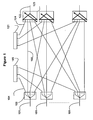
- a plurality of input channels 301 for example monomode optical fibers, are shown diagrammatically. These input channels are capable of receiving optical signals to channels belonging to a WDM wavelength channel grid.
- the wavelengths of the channels associated with the signals that can receive the input channels 301 are likely to change over time, for example under the control of a management system of the WDM network, not represented on the figure 3 . Thus, it may be that at certain times there is no common channel associated with signals received on different inputs. On the contrary, at other times, several input channels may receive signals on the same channel. For example, at a certain moment, a first input channel 301 may receive a signal on a channel of wavelength ⁇ 1, and a second input channel 301 may receive a second signal on a second channel of length ⁇ 1. wave ⁇ 2. At this moment, the signals carried by these two input channels will correspond to different channels. At another time, it may appear on the second input channel 301 a third signal on the wavelength channel ⁇ 1. At this time the two input channels will carry two signals to the same channel ⁇ 1.
- transfer and extraction couplers 303 positioned on each of the input channels 301 are shown.
- the couplers 303 have an output connected to an extraction channel 304 (for example, a optical fiber) and one or more transfer outputs connected to transfer paths 302 (for example one or more optical fibers).
- This configuration will be preferred when the elements represented on the figure 3 will be used to perform both the extraction and the transfer of signals, for example in an equipment type OADM (Optical Add / Drop Multiplexer) or Multiplexer Insertion / Extraction.
- OADM Optical Add / Drop Multiplexer
- the couplers 303 may be optical fiber-based power splitters having one input and two outputs and such that 90% of the power of the signals received on the input channel is transferred to the transfer path 302 and 10% of this power is extracted on the extraction outlet and transmitted to the extraction channel 304.
- FIG. 3 On the figure 3 are also represented several tunable demultiplexers 306.
- the extraction output of a coupler 303 is connected by a corresponding extraction channel 304, for example a monomode optical fiber, to the input of a corresponding demultiplexer 306.
- a corresponding extraction channel 304 for example a monomode optical fiber
- the tunable demultiplexers 306 are of the Wavelength Selective Switch (WSS) type.
- WSS tunable demultiplexers and their application as wavelength selective switches are described, inter alia, in US-A-2002/1 96520 , WO-2004/015469 and S. Mechels et al., IEEE Communication Magazine, March 2003, pp 88-94 .
- the outputs of the WSS demultiplexers are connected by first optical links 307 to star coupler inputs 308 having n inputs and m outputs.
- the power of a signal received on each of the n inputs of a coupler 308 is distributed over the m output channels of this coupler. This distribution is essentially the same regardless of the wavelength channel associated with the signal.
- a nxm coupler uniformly distributes, within manufacturing tolerances, the power of a signal received on any of its n inputs to each of its m outputs. Thus, if a signal is received at a channel of wavelength ⁇ 1 at an input of a coupler 308, an approximately equal fraction of this signal is found on each of the outputs of the coupler 308.
- the star couplers 308 can also consist of in passive couplers or amplified couplers as will be explained later in connection with the figure 5 .
- a star coupler 308 is connected by a second optical link 309, for example a monomode optical fiber, to a corresponding tunable receiver 311.
- a tunable receiver can be realized in several ways known to those skilled in the art.
- a tunable receiver 311 may consist of a tunable filter of wavelength channels, for example based on Bragg gratings, placed in front of a Positive-Intrinsic-Negative (PIN) photodiode.
- PIN Positive-Intrinsic-Negative
- Another embodiment may consist in using a coherent type tunable receiver consisting of a local optical oscillator and a mixer for receiving on photodiodes, for example of the PIN type, beats between the signal of the local oscillator and the signals present on an output of the star coupler 308.
- a coherent type tunable receiver consisting of a local optical oscillator and a mixer for receiving on photodiodes, for example of the PIN type, beats between the signal of the local oscillator and the signals present on an output of the star coupler 308.
- Other types of tunable receivers are possible.
- control unit 312 for adjusting by a control link 313 the tunable demultiplexers 306.
- the number of star couplers 308 is not necessarily equal to the number of demultiplexers 306.
- One skilled in the art is able to choose the number of star couplers 308 sufficient, given the number of outputs of demultiplexers 306 to connect, the number of tunable receivers 311 necessary, and values of the parameters n and m of the star couplers 308 used.
- the set consisting of the tunable demultiplexers 306, links 307 and 309, star couplers 308, tunable receivers 311, the control unit 312 and the control link 313 constitute an extraction module 305.
- This module extraction 305 can be used in a device as shown on the figure 1 , to realize the extraction module 105, or in other types of optical switching nodes.
- the device represented on the figure 3 has a property known by the general name of "directionless" in English, and signifying that receivers 311 are not permanently assigned to receive signals from certain particular inputs 301. On the contrary all 311 receivers on the figure 3 to receive signals on wavelength channels received by any of the input channels 301. Indeed, if a signal at a wavelength channel is received by an input channel 301, the demultiplexer 306 corresponding to this channel can be set by the control unit 312 and the link 313 so as to switch this signal to one of its outputs coupled to any of the star couplers, and thus reach any of the receivers tunable 311 connected to outputs of this star coupler.
- the use of a tunable receiver 311 makes it possible to filter a single channel signal out of several signals at wavelength channels present on the outputs of the corresponding star coupler.
- each detector 311 can receive signals at different channels depending on the channels received on the input channels 301 and the setting of the WSS demultiplexer between that receiver and the corresponding input channel.
- the device presented on the figure 3 at least partially resolves the contention of the wavelength channels.
- the control unit 312 can adjust these two demultiplexers via link 313 so as to these two signals are received by two different star coupler 308 and thus arrive at two different receivers 301 without collision between these two signals.
- the contention in wavelength is not necessarily solved in all cases by the device of the figure 3 .
- the device has 32 inputs 301, and these 32 inputs receive instantaneously signals at the same wavelength channel, and moreover, the number of star couplers 308 is less than 32, it is clear that the contention can not be fully resolved at that moment.
- a preferred embodiment of the device of the figure 3 is on the contrary that where the number of star couplers 308 is not less than the number of input channels 301.
- an advantageous implementation of the figure 3 can use 4 input channels 301, each of which can receive up to 80 80-wavelength waveform signals of a WDM spectrum on a 50GHz grid.
- the device of the figure 3 so that wavelength contention is solved statistically at certain times, or most of the time or systematically if we use a suitable dimensioning of the elements of the figure 3 .
- the total number of tunable receivers can be sized according to the required extraction capacity, that is to say the maximum number of signals to be extracted simultaneously at the level of the extraction module 305.
- the number of receivers Star coupler 308 limits the number of signals that can be received simultaneously on the same wavelength channel. So, if the device of the figure 3 uses 4 star couplers, and subject to the presence of other necessary elements on the figure 3 four signals at the same wavelength from four different input channels can be detected simultaneously.
- An advantageous embodiment therefore has a number of star couplers greater than or equal to the number of input channels.
- the minimum level of the optical signal-to-noise ratio to be obtained at the tunable receivers can also be taken into account to size this number of star couplers. Indeed, this ratio generally tends to decrease as the number of wavelength channels combined in the same coupler increases or when the number of star coupler ports increases.
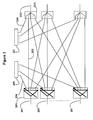
- the figure 4 illustrates a second embodiment of an extraction device which has the additional advantage of reducing the manufacturing cost, as will be explained.
- Such an extraction device can be used in an optical network, in particular in an optical signal switching device having a selection / combination type architecture.
- a plurality of input channels 401 for example monomode optical fibers, are schematically represented. These input channels are capable of receiving optical signals at wavelength channels.
- Transfer and extraction couplers 403 are positioned on each of the input channels 401. These couplers 403 are on the figure 4 tunable demultiplexers, for example WSS, whose output can be connected to an extraction channel 404 and other outputs connected to transfer channels 402. These tunable demultiplexers 404 can advantageously be those usually present on the signal channels. inputs of an optical multiplexer insertion / extraction, as for example indicated above in relation to the figure 2 .
- these fixed demultiplexers 406 are also shown.
- these fixed demultiplexers may be periodic band demultiplexers or demultiplexers.
- Band demultiplexers are known which are capable of separating signals on the same output from groups of adjacent channels of a wavelength grid. These demultiplexers can be made for example using dielectric multilayer type pass-through optical filters.
- Periodic demultiplexers are also known, for example silica on silicon-type guide network (AWG Array Waveguide Gratting, in English). These periodic demultiplexers make it possible to extract signals on each of their outputs from channels of wavelengths spaced a multiple of the pitch of a wavelength grid, this multiplicity factor corresponding to the periodicity of the demultiplexer.
- These periodic demultiplexers may for example be made of silica on silicon or GaInAsP / InP type semiconductor material.
- the extraction output of a tunable demultiplexer 403, for example a WSS, is connected by a corresponding extraction channel 404, for example a monomode optical fiber, to the input of a corresponding demultiplexer fixed demultiplexer 406 of the demultiplexer type. of bands or periodic demultiplexer.
- a corresponding extraction channel 404 for example a monomode optical fiber
- an input channel 401 receives a plurality of optical signals at wavelength channels, a portion of the power of some of these wavelength signals may be received at the input of the corresponding fixed demultiplexer 406. via the extraction output of the tunable demultiplexer 403 and the corresponding extraction channel 404.
- the outputs of the fixed demultiplexers 406 are connected by first optical links 407 to star coupler inputs 408 having n inputs and m outputs.
- star coupler inputs 408 may be of the passive type or amplified type, as will be explained later in connection with the figure 5 .
- Each of the outputs of a star coupler 408 is connected by a second optical link 409, for example a monomode optical fiber, to a corresponding tunable receiver 411.
- the number of star couplers 408 is not necessarily equal to the number of demultiplexers 406. Those skilled in the art are able to choose the number of star couplers 408 sufficient, given the number of outputs of demultiplexers 406 to connect, the number of tunable receivers 411 needed, and the values of the parameters n and m of star couplers 408 used.
- This extraction module 405 can be used in a device as shown in FIG. the figure 2 , to achieve the extraction module 205.
- the device of the figure 4 also presents the characteristic of being "directionless". Indeed, provided that a star coupler 408 is connected to all fixed demultiplexers 406, any receiver 411 connected to an output of this star coupler 408 can receive a signal from any of the input channels 401. This signal will be transmitted via the tunable demultiplexer 403, the extraction channel 404 and the fixed demultiplexer 406 corresponding. However, because of the fixity of the demultiplexers 406, this signal can only be received on certain wavelength channels for each given input channel. The "directionless" property is therefore achieved with less flexibility by the device according to the figure 4 .
- a tunable receiver 411 can receive signals of a given input channel only on wavelength channels for which the fixed demultiplexer 406 associated with this input channel is passing towards the star coupler 408 to which this receiver is connected.
- the device of the figure 4 significantly reduces the cost of implementation compared to the device of the figure 3 .
- the tunable demultiplexer 403 is not necessarily specific to the extraction function in question.
- this tunable demultiplexer can jointly perform a function of selecting the signals to be transferred, in particular in a switching device having a selection / combination architecture as in the figure 2 .
- a fixed demultiplexer 406 is cost significantly less than the cost of a tunable demultiplexer as used in FIG. figure 3 .
- the devices of figures 3 and 4 thus have the advantage of solving in a statistical or systematic way the wavelength contention.
- the device of the figure 4 moreover allows a compromise allowing a reduction of the cost of realization, at the expense of the flexibility of the properties "directionless” and “colorless”, as explained previously.
- the figure 5 represents two alternative embodiments of a star coupler, with n inputs and m outputs, and which can be used to make the star couplers 308 or 408 in the devices of figures 3 and 4 .
- 501 we have represented the section method of coupling a star coupler of the passive coupler type having a plurality of inputs and a plurality of outputs.
- Such a coupler can be realized using known technologies based on single-mode optical fibers, silicon-on-silicon guides and other technologies. As will be recognized by those skilled in the art, the insertion losses of such a coupler are essentially dependent on the number of inputs and outputs of these couplers.
- the choice of the number n of inputs and the number m of outputs of star couplers 308, 408 depends on the number of input channels 301, 401, the number of signals on the same channels that can be extracted simultaneously, and other parameters. again.
- the insertion losses of star couplers nxm are proportional to the logarithm of the maximum between m and n. Consequently, because of the insertion losses between the input channels 301, 401 and the receivers 311, 411, and in particular those due to the presence of the star couplers 308, 408, the power of the signal received by each receiver 311 , 411 can be very weak.
- insertion losses essentially consist of the sum of the insertion losses of the transfer and extraction coupler 303, 403, the demultiplexer 306, 406 and the star coupler 308, 408, and other losses.
- the devices described on the figures 3 and 4 can therefore advantageously use the star coupler active coupler type shown schematically on the figure 5 at 502, 503 and 504.
- an optical amplifier element inserted between a coupler nx 1 at 502 and a divider 1x m at 504.
- the coupler 503 or divider 504 may be made of known technologies based on single-mode optical fibers or silica on silicon or semiconductor GaInAsP / InP or other technologies.
- the amplifier element may be a localized gain stage realized by an optically pumped and optically pumped fiber, or a GaInAsP / InP type semiconductor amplifier or other types of amplifiers, including distributed amplification.
- the coupler nx 1 at the number 502, the coupling section at the number 503 and the divisor 1 xm at the number 504 could be made based on single-mode optic fibers doped with erbium and optically pumped, thus producing an amplification structure distributed.
- no transfer path 302 is provided.
- all the signal power received by an input channel of a coupler 303 is transmitted on the corresponding extraction channel 304.
- This particular variant can be achieved with a coupler 303 which is then reduced to a device with an input and an output, for example a section of monomode optical fiber.
- Such an embodiment may be useful for extracting signals at a node located at the end of a branch of the network, for example in a passive optical network.
Landscapes
- Engineering & Computer Science (AREA)
- Computer Networks & Wireless Communication (AREA)
- Signal Processing (AREA)
- Optical Communication System (AREA)
Claims (10)
- Vorrichtung zum Mehrwege-Abzweigen von WDM-Kanälen, umfassend:Eine Vielzahl von Eingangspfaden (301, 401), welche fähig sind, WDM-Kanäle zu empfangen,einen ersten Demultiplexer (306, 406), dessen einer Eingang mit einem ersten der besagten Eingangspfade verbunden ist,einen zweiten Demultiplexer (306, 406), dessen einer Eingang mit einem zweiten der besagten Eingangspfade verbunden ist,einen ersten Sternkoppler (308, 408) mit einer Vielzahl von Eingängen, wobei ein erster Eingang des besagten Sternkopplers mit einem ersten Ausgang des besagten ersten Demultiplexers verbunden ist und ein zweiter Eingang des besagten Sternkopplers mit einem ersten Ausgang des besagten zweiten Demultiplexers verbunden ist,einen zweiten Sternkoppler (308, 408) mit einer Vielzahl von Eingängen, wobei ein erster Eingang des besagten zweiten Sternkopplers mit einem zweiten Ausgang des besagten ersten Demultiplexers verbunden ist, und ein zweiter Eingang des besagten zweiten Sternkopplers mit einem zweiten Ausgang des besagten zweiten Demultiplexers verbunden ist,und eine Vielzahl von abstimmbaren Empfängern (311, 411), wobei ein erster der abstimmbaren Empfänger (311, 411) mit einem ersten Ausgang des besagten ersten Sternkopplers verbunden ist, ein zweiter der abstimmbaren Empfänger (311, 411) mit einem zweiten Ausgang des besagten ersten Sternkopplers verbunden ist, und ein dritter der abstimmbaren Empfänger (311, 411) mit einem Ausgang des besagten zweiten Sternkopplers verbunden ist,dadurch gekennzeichnet, dass sie einen ersten Abzweigkoppler (303, 403), welcher auf dem ersten Eingangspfad angeordnet ist, und einen zweiten Abzweigkoppler (303, 403), welcher auf dem zweiten Eingangspfad angeordnet ist, umfasst,wobei der erste Abzweigkoppler einen einzigen Abzweigausgang umfasst, wobei der Abzweigausgang des besagten ersten Abzweigkopplers mit dem Eingang des ersten Demultiplexers (306, 406) verbunden ist,wobei der zweite Abzweigkoppler einen einzigen Abzweigausgang umfasst, wobei der Abzweigausgang des besagten zweiten Abzweigkopplers mit dem Eingang des zweiten Demultiplexers (306, 406) verbunden ist.
- Abzweigungsvorrichtung nach Anspruch 1, dadurch gekennzeichnet, dass die besagten Demultiplexer abstimmbare Demultiplexer vom Typ WSS (306) umfassen.
- Abzweigungsvorrichtung nach Anspruch 2, wobei die besagten abstimmbaren Demultiplexer vom Typ WSS (306) derart eingestellt sind, dass der besagte erste und der besagte zweite Eingang des besagten ersten Sternkopplers aus dem besagten ersten Eingangspfad und aus dem besagten zweiten Eingangspfad abgezweigte Signale nicht simultan auf einem selben Wellenlängenkanal empfangen können.
- Abzweigungsvorrichtung nach einem der Ansprüche 1 bis 3, dadurch gekennzeichnet, dass die besagten Abzweigkoppler Leistungsteiler (303) umfassen, welche den besagten Abzweigausgang und einen Übertragungsausgang aufweisen.
- Abzweigungsvorrichtung nach Anspruch 1, dadurch gekennzeichnet, dass die besagten Abzweigkoppler abstimmbare Demultiplexer vom Typ WSS (403) mit einem Eingang, welcher mit einem besagten Eingangspfad verbunden ist, dem besagten Abzweigausgang und einem Übertragungsausgang umfassen, und dass die besagten Demultiplexer fest eingestellte Demultiplexer (406) umfassen.
- Abzweigungsvorrichtung nach Anspruch 5, dadurch gekennzeichnet, dass die fest eingestellten Demultiplexer (406) periodische Demultiplexer oder Wellenlängenbanddemultiplexer umfassen.
- Abzweigungsvorrichtung nach einem der Ansprüche 5 und 6, dadurch gekennzeichnet, dass die besagten fest eingestellten Demultiplexer derart ausgelegt und mit dem besagten ersten Sternkoppler verbunden sind, dass der besagte erste und der besagte zweite Eingang des besagten ersten Stenkopplers aus dem besagten ersten Eingangspfad und aus dem besagten zweiten Eingangspfad abgezweigte Signale nicht simultan auf einem selben Wellenlängenkanal empfangen können.
- Abzweigungsvorrichtung nach einem der Ansprüche 1 bis 7, dadurch gekennzeichnet, dass die besagten Sternkoppler passive Koppler (501) umfassen.
- Vorrichtung zum optischen Mehrwege-Abzweigen von WDM-Kanälen nach einem der Ansprüche 1 bis 7, dadurch gekennzeichnet, dass die besagten Sternkoppler verstärkte Kuppler (502, 503, 504) umfassen.
- Abzweigungsvorrichtung nach einem der Ansprüche 1 bis 9, dadurch gekennzeichnet, dass die besagten abstimmbaren Empfänger kohärente Empfänger (311, 411) umfassen, welche über optische Verbindungen (309, 409) direkt mit den Ausgängen der Sternkoppler verbunden sind.
Applications Claiming Priority (1)
| Application Number | Priority Date | Filing Date | Title |
|---|---|---|---|
| FR0903421A FR2947915B1 (fr) | 2009-07-10 | 2009-07-10 | Dispositif d'extraction multivoies de canaux wdm |
Publications (2)
| Publication Number | Publication Date |
|---|---|
| EP2282430A1 EP2282430A1 (de) | 2011-02-09 |
| EP2282430B1 true EP2282430B1 (de) | 2013-05-29 |
Family
ID=41507813
Family Applications (1)
| Application Number | Title | Priority Date | Filing Date |
|---|---|---|---|
| EP10169009.7A Not-in-force EP2282430B1 (de) | 2009-07-10 | 2010-07-09 | Vorrichtung zum Mehrwege-Abzweigen von WDM-Kanälen |
Country Status (2)
| Country | Link |
|---|---|
| EP (1) | EP2282430B1 (de) |
| FR (1) | FR2947915B1 (de) |
Citations (1)
| Publication number | Priority date | Publication date | Assignee | Title |
|---|---|---|---|---|
| US20080056715A1 (en) * | 2006-08-30 | 2008-03-06 | Fujitsu Limited | Optical transmission apparatus having OADM function |
Family Cites Families (4)
| Publication number | Priority date | Publication date | Assignee | Title |
|---|---|---|---|---|
| US6657770B2 (en) | 2001-06-22 | 2003-12-02 | Lucent Technologies Inc. | Programmable optical multiplexer/demultiplexer |
| WO2004015469A1 (en) | 2002-08-08 | 2004-02-19 | The Regents Of The University Of California | Wavelength-selective 1xn2 switches with two-dimensional input/output fiber arrays |
| US7899334B2 (en) * | 2003-01-31 | 2011-03-01 | Ciena Corporation | Signal distribution module for a directionless reconfigurable optical add/drop multiplexer |
| DE102005041371A1 (de) * | 2005-04-28 | 2006-11-09 | Siemens Ag | Anordnungen für eine Add-Drop-Einrichtung und Übertragungssystem für Wellenlängen-Multiplex-Signale |
-
2009
- 2009-07-10 FR FR0903421A patent/FR2947915B1/fr not_active Expired - Fee Related
-
2010
- 2010-07-09 EP EP10169009.7A patent/EP2282430B1/de not_active Not-in-force
Patent Citations (1)
| Publication number | Priority date | Publication date | Assignee | Title |
|---|---|---|---|---|
| US20080056715A1 (en) * | 2006-08-30 | 2008-03-06 | Fujitsu Limited | Optical transmission apparatus having OADM function |
Also Published As
| Publication number | Publication date |
|---|---|
| FR2947915B1 (fr) | 2011-11-11 |
| EP2282430A1 (de) | 2011-02-09 |
| FR2947915A1 (fr) | 2011-01-14 |
Similar Documents
| Publication | Publication Date | Title |
|---|---|---|
| EP2141842B1 (de) | Schaltelement für optische Signale | |
| EP0802645B1 (de) | Optischer Verstärker mit variabler Verstärkung und konstantem Durchlassband und automatisches Verluständerungenkompensationssystem in einer optischen Verbindung mit einem solchen Verstärker | |
| EP1969748A1 (de) | Optische übertragung zwischen einem zentralen endgerät und mehreren client-endgeräten über ein optisches netzwerk | |
| EP1088417B1 (de) | Verfahren und vorrichtung zur abzweigung von optischen kanälen in einem optischen übertragungssystem | |
| EP1608096A1 (de) | Verfahren zur Aufrüstung eines optischen Übertragungsnetzwerks, optisches Übertragungsnetz und zugehöriger optischer Übertragungsknoten | |
| JP2001217777A (ja) | 光波長分岐/挿入マルチプレクサ及びそれに使用されるフィルタ要素 | |
| WO2003028263A1 (fr) | Systeme de demultiplexage optique de bandes de longueurs d'ondes | |
| FR2933256A1 (fr) | Dispositif de commutation de signaux optiques | |
| EP0697800B1 (de) | Optische Rangierverteiler | |
| EP1657840B1 (de) | DWDM-Kommunikationsnetz mit periodischer Wellenlängen-Multiplexierung | |
| EP2282430B1 (de) | Vorrichtung zum Mehrwege-Abzweigen von WDM-Kanälen | |
| EP1213866B1 (de) | Verschachtelte Banden Demultiplex-Multiplex-System | |
| EP2160045B1 (de) | Knoten zur Kommunikation von optischen Paketen | |
| EP1398896A1 (de) | Frequenzkamm für ein Netzwerk mit optischer Frequenzmultiplexierung | |
| EP1986361B1 (de) | Optische Schaltvorrichtung für transparentes optisches Netz | |
| EP1273119B1 (de) | Lichtwellenleiter-übertragungseinrichtung mit wellenlängenmultiplex | |
| EP1804407B1 (de) | Accessknoten für optisches Ringnetzwerk | |
| FR2937815A1 (fr) | Dispositif de commutation de signaux optiques | |
| EP2007049B1 (de) | Vorrichtung zur Übertragung optischer Signale mit unterschiedlichen Datenraten | |
| EP1379100B1 (de) | Optischer Kreuzschienenverteiler mit granularer Architektur | |
| EP1098465A1 (de) | Verfahren zum Abführen von einem Kanal für ein optisches Wellenlängemultiplex-Übertragungsystem und Vorrichtung zur Anwendung dieses Verfahrens | |
| FR2923336A1 (fr) | Transmetteur accordable en longueurs d'onde et a filtrage integre pour un reseau de communication optique (d)wdm, et transpondeur correspondant | |
| FR2953348A1 (fr) | Dispositif d'extraction de canaux wdm | |
| EP1503529A1 (de) | Interferometrisches System zur Auswahl spektraler Komponenten aus einer optischen Strahl |
Legal Events
| Date | Code | Title | Description |
|---|---|---|---|
| PUAI | Public reference made under article 153(3) epc to a published international application that has entered the european phase |
Free format text: ORIGINAL CODE: 0009012 |
|
| AK | Designated contracting states |
Kind code of ref document: A1 Designated state(s): AL AT BE BG CH CY CZ DE DK EE ES FI FR GB GR HR HU IE IS IT LI LT LU LV MC MK MT NL NO PL PT RO SE SI SK SM TR |
|
| AX | Request for extension of the european patent |
Extension state: BA ME RS |
|
| 17P | Request for examination filed |
Effective date: 20110809 |
|
| 17Q | First examination report despatched |
Effective date: 20120116 |
|
| GRAP | Despatch of communication of intention to grant a patent |
Free format text: ORIGINAL CODE: EPIDOSNIGR1 |
|
| GRAS | Grant fee paid |
Free format text: ORIGINAL CODE: EPIDOSNIGR3 |
|
| GRAA | (expected) grant |
Free format text: ORIGINAL CODE: 0009210 |
|
| AK | Designated contracting states |
Kind code of ref document: B1 Designated state(s): AL AT BE BG CH CY CZ DE DK EE ES FI FR GB GR HR HU IE IS IT LI LT LU LV MC MK MT NL NO PL PT RO SE SI SK SM TR |
|
| REG | Reference to a national code |
Ref country code: GB Ref legal event code: FG4D Free format text: NOT ENGLISH |
|
| REG | Reference to a national code |
Ref country code: CH Ref legal event code: EP |
|
| REG | Reference to a national code |
Ref country code: AT Ref legal event code: REF Ref document number: 614965 Country of ref document: AT Kind code of ref document: T Effective date: 20130615 |
|
| REG | Reference to a national code |
Ref country code: IE Ref legal event code: FG4D Free format text: LANGUAGE OF EP DOCUMENT: FRENCH |
|
| REG | Reference to a national code |
Ref country code: DE Ref legal event code: R096 Ref document number: 602010007245 Country of ref document: DE Effective date: 20130725 |
|
| 111Z | Information provided on other rights and legal means of execution |
Free format text: AL AT BE BG CH CY CZ DE DK EE ES FI FR GB GR HR HU IE IS IT LI LT LU LV MC MK MT NL NO PL PT RO SE SI SK SM TR Effective date: 20130410 |
|
| REG | Reference to a national code |
Ref country code: AT Ref legal event code: MK05 Ref document number: 614965 Country of ref document: AT Kind code of ref document: T Effective date: 20130529 |
|
| REG | Reference to a national code |
Ref country code: LT Ref legal event code: MG4D |
|
| PG25 | Lapsed in a contracting state [announced via postgrant information from national office to epo] |
Ref country code: LT Free format text: LAPSE BECAUSE OF FAILURE TO SUBMIT A TRANSLATION OF THE DESCRIPTION OR TO PAY THE FEE WITHIN THE PRESCRIBED TIME-LIMIT Effective date: 20130529 Ref country code: FI Free format text: LAPSE BECAUSE OF FAILURE TO SUBMIT A TRANSLATION OF THE DESCRIPTION OR TO PAY THE FEE WITHIN THE PRESCRIBED TIME-LIMIT Effective date: 20130529 Ref country code: SI Free format text: LAPSE BECAUSE OF FAILURE TO SUBMIT A TRANSLATION OF THE DESCRIPTION OR TO PAY THE FEE WITHIN THE PRESCRIBED TIME-LIMIT Effective date: 20130529 Ref country code: GR Free format text: LAPSE BECAUSE OF FAILURE TO SUBMIT A TRANSLATION OF THE DESCRIPTION OR TO PAY THE FEE WITHIN THE PRESCRIBED TIME-LIMIT Effective date: 20130830 Ref country code: IS Free format text: LAPSE BECAUSE OF FAILURE TO SUBMIT A TRANSLATION OF THE DESCRIPTION OR TO PAY THE FEE WITHIN THE PRESCRIBED TIME-LIMIT Effective date: 20130929 Ref country code: NO Free format text: LAPSE BECAUSE OF FAILURE TO SUBMIT A TRANSLATION OF THE DESCRIPTION OR TO PAY THE FEE WITHIN THE PRESCRIBED TIME-LIMIT Effective date: 20130829 Ref country code: SE Free format text: LAPSE BECAUSE OF FAILURE TO SUBMIT A TRANSLATION OF THE DESCRIPTION OR TO PAY THE FEE WITHIN THE PRESCRIBED TIME-LIMIT Effective date: 20130529 Ref country code: AT Free format text: LAPSE BECAUSE OF FAILURE TO SUBMIT A TRANSLATION OF THE DESCRIPTION OR TO PAY THE FEE WITHIN THE PRESCRIBED TIME-LIMIT Effective date: 20130529 Ref country code: PT Free format text: LAPSE BECAUSE OF FAILURE TO SUBMIT A TRANSLATION OF THE DESCRIPTION OR TO PAY THE FEE WITHIN THE PRESCRIBED TIME-LIMIT Effective date: 20130930 Ref country code: ES Free format text: LAPSE BECAUSE OF FAILURE TO SUBMIT A TRANSLATION OF THE DESCRIPTION OR TO PAY THE FEE WITHIN THE PRESCRIBED TIME-LIMIT Effective date: 20130909 |
|
| REG | Reference to a national code |
Ref country code: NL Ref legal event code: VDEP Effective date: 20130529 |
|
| PG25 | Lapsed in a contracting state [announced via postgrant information from national office to epo] |
Ref country code: HR Free format text: LAPSE BECAUSE OF FAILURE TO SUBMIT A TRANSLATION OF THE DESCRIPTION OR TO PAY THE FEE WITHIN THE PRESCRIBED TIME-LIMIT Effective date: 20130529 Ref country code: PL Free format text: LAPSE BECAUSE OF FAILURE TO SUBMIT A TRANSLATION OF THE DESCRIPTION OR TO PAY THE FEE WITHIN THE PRESCRIBED TIME-LIMIT Effective date: 20130529 Ref country code: BG Free format text: LAPSE BECAUSE OF FAILURE TO SUBMIT A TRANSLATION OF THE DESCRIPTION OR TO PAY THE FEE WITHIN THE PRESCRIBED TIME-LIMIT Effective date: 20130829 |
|
| PG25 | Lapsed in a contracting state [announced via postgrant information from national office to epo] |
Ref country code: LV Free format text: LAPSE BECAUSE OF FAILURE TO SUBMIT A TRANSLATION OF THE DESCRIPTION OR TO PAY THE FEE WITHIN THE PRESCRIBED TIME-LIMIT Effective date: 20130529 |
|
| BERE | Be: lapsed |
Owner name: ALCATEL LUCENT Effective date: 20130731 |
|
| PG25 | Lapsed in a contracting state [announced via postgrant information from national office to epo] |
Ref country code: CZ Free format text: LAPSE BECAUSE OF FAILURE TO SUBMIT A TRANSLATION OF THE DESCRIPTION OR TO PAY THE FEE WITHIN THE PRESCRIBED TIME-LIMIT Effective date: 20130529 Ref country code: SK Free format text: LAPSE BECAUSE OF FAILURE TO SUBMIT A TRANSLATION OF THE DESCRIPTION OR TO PAY THE FEE WITHIN THE PRESCRIBED TIME-LIMIT Effective date: 20130529 Ref country code: DK Free format text: LAPSE BECAUSE OF FAILURE TO SUBMIT A TRANSLATION OF THE DESCRIPTION OR TO PAY THE FEE WITHIN THE PRESCRIBED TIME-LIMIT Effective date: 20130529 Ref country code: EE Free format text: LAPSE BECAUSE OF FAILURE TO SUBMIT A TRANSLATION OF THE DESCRIPTION OR TO PAY THE FEE WITHIN THE PRESCRIBED TIME-LIMIT Effective date: 20130529 |
|
| PG25 | Lapsed in a contracting state [announced via postgrant information from national office to epo] |
Ref country code: NL Free format text: LAPSE BECAUSE OF FAILURE TO SUBMIT A TRANSLATION OF THE DESCRIPTION OR TO PAY THE FEE WITHIN THE PRESCRIBED TIME-LIMIT Effective date: 20130529 Ref country code: IT Free format text: LAPSE BECAUSE OF FAILURE TO SUBMIT A TRANSLATION OF THE DESCRIPTION OR TO PAY THE FEE WITHIN THE PRESCRIBED TIME-LIMIT Effective date: 20130529 Ref country code: RO Free format text: LAPSE BECAUSE OF FAILURE TO SUBMIT A TRANSLATION OF THE DESCRIPTION OR TO PAY THE FEE WITHIN THE PRESCRIBED TIME-LIMIT Effective date: 20130529 |
|
| PLBE | No opposition filed within time limit |
Free format text: ORIGINAL CODE: 0009261 |
|
| STAA | Information on the status of an ep patent application or granted ep patent |
Free format text: STATUS: NO OPPOSITION FILED WITHIN TIME LIMIT |
|
| REG | Reference to a national code |
Ref country code: IE Ref legal event code: MM4A |
|
| PG25 | Lapsed in a contracting state [announced via postgrant information from national office to epo] |
Ref country code: BE Free format text: LAPSE BECAUSE OF NON-PAYMENT OF DUE FEES Effective date: 20130731 |
|
| 26N | No opposition filed |
Effective date: 20140303 |
|
| REG | Reference to a national code |
Ref country code: DE Ref legal event code: R097 Ref document number: 602010007245 Country of ref document: DE Effective date: 20140303 |
|
| PG25 | Lapsed in a contracting state [announced via postgrant information from national office to epo] |
Ref country code: IE Free format text: LAPSE BECAUSE OF NON-PAYMENT OF DUE FEES Effective date: 20130709 |
|
| REG | Reference to a national code |
Ref country code: CH Ref legal event code: PCOW Free format text: NEW ADDRESS: 148/152 ROUTE DE LA REINE, 92100 BOULOGNE-BILLANCOURT (FR) |
|
| REG | Reference to a national code |
Ref country code: CH Ref legal event code: PL |
|
| PG25 | Lapsed in a contracting state [announced via postgrant information from national office to epo] |
Ref country code: LI Free format text: LAPSE BECAUSE OF NON-PAYMENT OF DUE FEES Effective date: 20140731 Ref country code: CH Free format text: LAPSE BECAUSE OF NON-PAYMENT OF DUE FEES Effective date: 20140731 |
|
| PG25 | Lapsed in a contracting state [announced via postgrant information from national office to epo] |
Ref country code: SM Free format text: LAPSE BECAUSE OF FAILURE TO SUBMIT A TRANSLATION OF THE DESCRIPTION OR TO PAY THE FEE WITHIN THE PRESCRIBED TIME-LIMIT Effective date: 20130529 |
|
| REG | Reference to a national code |
Ref country code: FR Ref legal event code: PLFP Year of fee payment: 6 |
|
| PG25 | Lapsed in a contracting state [announced via postgrant information from national office to epo] |
Ref country code: TR Free format text: LAPSE BECAUSE OF FAILURE TO SUBMIT A TRANSLATION OF THE DESCRIPTION OR TO PAY THE FEE WITHIN THE PRESCRIBED TIME-LIMIT Effective date: 20130529 Ref country code: CY Free format text: LAPSE BECAUSE OF FAILURE TO SUBMIT A TRANSLATION OF THE DESCRIPTION OR TO PAY THE FEE WITHIN THE PRESCRIBED TIME-LIMIT Effective date: 20130529 Ref country code: MT Free format text: LAPSE BECAUSE OF FAILURE TO SUBMIT A TRANSLATION OF THE DESCRIPTION OR TO PAY THE FEE WITHIN THE PRESCRIBED TIME-LIMIT Effective date: 20130529 |
|
| PG25 | Lapsed in a contracting state [announced via postgrant information from national office to epo] |
Ref country code: HU Free format text: LAPSE BECAUSE OF FAILURE TO SUBMIT A TRANSLATION OF THE DESCRIPTION OR TO PAY THE FEE WITHIN THE PRESCRIBED TIME-LIMIT; INVALID AB INITIO Effective date: 20100709 Ref country code: LU Free format text: LAPSE BECAUSE OF NON-PAYMENT OF DUE FEES Effective date: 20130709 Ref country code: MC Free format text: LAPSE BECAUSE OF FAILURE TO SUBMIT A TRANSLATION OF THE DESCRIPTION OR TO PAY THE FEE WITHIN THE PRESCRIBED TIME-LIMIT Effective date: 20130529 Ref country code: MK Free format text: LAPSE BECAUSE OF FAILURE TO SUBMIT A TRANSLATION OF THE DESCRIPTION OR TO PAY THE FEE WITHIN THE PRESCRIBED TIME-LIMIT Effective date: 20130529 |
|
| REG | Reference to a national code |
Ref country code: FR Ref legal event code: PLFP Year of fee payment: 7 |
|
| REG | Reference to a national code |
Ref country code: FR Ref legal event code: PLFP Year of fee payment: 8 |
|
| PGFP | Annual fee paid to national office [announced via postgrant information from national office to epo] |
Ref country code: GB Payment date: 20170719 Year of fee payment: 8 Ref country code: FR Payment date: 20170724 Year of fee payment: 8 Ref country code: DE Payment date: 20170724 Year of fee payment: 8 |
|
| PG25 | Lapsed in a contracting state [announced via postgrant information from national office to epo] |
Ref country code: AL Free format text: LAPSE BECAUSE OF FAILURE TO SUBMIT A TRANSLATION OF THE DESCRIPTION OR TO PAY THE FEE WITHIN THE PRESCRIBED TIME-LIMIT Effective date: 20130529 |
|
| REG | Reference to a national code |
Ref country code: DE Ref legal event code: R119 Ref document number: 602010007245 Country of ref document: DE |
|
| GBPC | Gb: european patent ceased through non-payment of renewal fee |
Effective date: 20180709 |
|
| PG25 | Lapsed in a contracting state [announced via postgrant information from national office to epo] |
Ref country code: FR Free format text: LAPSE BECAUSE OF NON-PAYMENT OF DUE FEES Effective date: 20180731 Ref country code: GB Free format text: LAPSE BECAUSE OF NON-PAYMENT OF DUE FEES Effective date: 20180709 Ref country code: DE Free format text: LAPSE BECAUSE OF NON-PAYMENT OF DUE FEES Effective date: 20190201 |
|
| REG | Reference to a national code |
Ref country code: GB Ref legal event code: 732E Free format text: REGISTERED BETWEEN 20190429 AND 20190502 |
|
| REG | Reference to a national code |
Ref country code: DE Ref legal event code: R082 Ref document number: 602010007245 Country of ref document: DE Representative=s name: MENZIETTI WETZEL, DE Ref country code: DE Ref legal event code: R081 Ref document number: 602010007245 Country of ref document: DE Owner name: PROVENANCE ASSET GROUP LLC, PITTSFORD, US Free format text: FORMER OWNER: ALCATEL LUCENT, PARIS, FR |