EP0791553B1 - Bremsanordnung für eine in einem Gehäuse eingebaute selbstaufwickelnde Kabeltrommel - Google Patents
Bremsanordnung für eine in einem Gehäuse eingebaute selbstaufwickelnde Kabeltrommel Download PDFInfo
- Publication number
- EP0791553B1 EP0791553B1 EP97101642A EP97101642A EP0791553B1 EP 0791553 B1 EP0791553 B1 EP 0791553B1 EP 97101642 A EP97101642 A EP 97101642A EP 97101642 A EP97101642 A EP 97101642A EP 0791553 B1 EP0791553 B1 EP 0791553B1
- Authority
- EP
- European Patent Office
- Prior art keywords
- cable
- winding
- housing
- brake
- braking
- Prior art date
- Legal status (The legal status is an assumption and is not a legal conclusion. Google has not performed a legal analysis and makes no representation as to the accuracy of the status listed.)
- Expired - Lifetime
Links
- 238000004804 winding Methods 0.000 title claims description 18
- 230000000694 effects Effects 0.000 claims description 6
- 238000000034 method Methods 0.000 claims description 5
- 230000000630 rising effect Effects 0.000 claims description 3
- 238000000605 extraction Methods 0.000 claims 1
- 230000000903 blocking effect Effects 0.000 description 4
- 238000013459 approach Methods 0.000 description 1
- 238000004519 manufacturing process Methods 0.000 description 1
- 230000007704 transition Effects 0.000 description 1
Images

Classifications
-
- B—PERFORMING OPERATIONS; TRANSPORTING
- B65—CONVEYING; PACKING; STORING; HANDLING THIN OR FILAMENTARY MATERIAL
- B65H—HANDLING THIN OR FILAMENTARY MATERIAL, e.g. SHEETS, WEBS, CABLES
- B65H75/00—Storing webs, tapes, or filamentary material, e.g. on reels
- B65H75/02—Cores, formers, supports, or holders for coiled, wound, or folded material, e.g. reels, spindles, bobbins, cop tubes, cans, mandrels or chucks
- B65H75/34—Cores, formers, supports, or holders for coiled, wound, or folded material, e.g. reels, spindles, bobbins, cop tubes, cans, mandrels or chucks specially adapted or mounted for storing and repeatedly paying-out and re-storing lengths of material provided for particular purposes, e.g. anchored hoses, power cables
- B65H75/38—Cores, formers, supports, or holders for coiled, wound, or folded material, e.g. reels, spindles, bobbins, cop tubes, cans, mandrels or chucks specially adapted or mounted for storing and repeatedly paying-out and re-storing lengths of material provided for particular purposes, e.g. anchored hoses, power cables involving the use of a core or former internal to, and supporting, a stored package of material
- B65H75/44—Constructional details
- B65H75/4418—Arrangements for stopping winding or unwinding; Arrangements for releasing the stop means
- B65H75/4421—Arrangements for stopping winding or unwinding; Arrangements for releasing the stop means acting directly on the material
-
- H—ELECTRICITY
- H02—GENERATION; CONVERSION OR DISTRIBUTION OF ELECTRIC POWER
- H02G—INSTALLATION OF ELECTRIC CABLES OR LINES, OR OF COMBINED OPTICAL AND ELECTRIC CABLES OR LINES
- H02G11/00—Arrangements of electric cables or lines between relatively-movable parts
- H02G11/02—Arrangements of electric cables or lines between relatively-movable parts using take-up reel or drum
Definitions
- the invention relates to a brake arrangement for one in one Housing built-in self-winding cable drum according to the Preamble of claim 1.
- Such a brake arrangement is through DE-A-29 11 506 known.
- this known brake arrangement is as Brake member is provided with a splined roller, those with stub axles attached to it in slotted slots is rotatably mounted.
- the backdrop slots are in the side walls of a cable outlet opening and are in Extension direction of the cable is inclined.
- the roll is through the cable something taken out in the pull-out direction and is thereby of the sloping course of the slot slots slightly raised compared to the cable.
- the role loses their braking effect and the cable can from cable drum subtracted from. After the removal process and Letting go of the cable comes up the winding force of the Cable drum to the effect that the cable rewind tries.
- BE-A-424 812 also provides a device for blocking a hose against self-winding is known.
- the hose is both at Unwinding as well as when intentionally winding up in trough-like depressions of two each other opposite roles performed.
- At least one of the rollers is mounted eccentrically. If you want to block the hose to prevent it from winding up automatically, the hose is directed laterally by an operator Traction from the trough-like recesses of the rollers to one of the side areas of the rolls pulled. This creates a strong friction connection between the hose and the rollers. After the operator releases the hose, it moves by the tensile force exerted on it by the automatic winding device in the winding direction.
- the invention is based, with a built in a vacuum cleaner housing, the task self-winding cable drum that blocks the automatic winding of the cable
- the problems posed are solved by the features of claim 1 specified characteristics.
- the one to be wound up serves Cable itself as a release element to cancel the braking effect.
- the braking effect requires little effort, so that even without holding the vacuum cleaner housing the cable out of its respective Blocking position can be pulled.
- the brake roller by an upward directional cable pull raised accordingly, thereby giving the cable to widen free.
- a change in position of the brake roller which releases the cable for the winding process is by a corresponding pulling force exerted on the cable, in that the slotted slots in relation to the pull-out direction of the cable initially rising slightly run and then lead steeply upwards.
- Brake assembly can be directly in the housing one in the drawing not shown self-winding cable drum or separated from it, for example, in the housing of a vacuum cleaner be installed. In this case it is also Cable drum arranged in the vacuum cleaner housing.
- the brake assembly consists of a brake roller 2, the laterally projecting axle journal 3 in link slots 4 is rotatably mounted.
- the slotted slots 4 are in the side walls 5 one on the cable drum itself or on the cable outlet opening 6 formed in the vacuum cleaner housing.
- the Setting slots 4 in the pull-out direction one on the Cable drum located cable 7 first a flat increasing course 8 on. Following this flat Course 8 are the slots 4 in another Area 9 climbed steeply.
- the brake arrangement shown in Figs. 1 and 2 works as follows: The cable 7 is if necessary from the cable drum deducted.
- the brake roller 2 is from the in Fig.1 shown braking position in the pull-out direction of the cable 7 taken and migrates into the backdrop slots 4 small piece in the unwinding direction of the cable 7.
- the brake roller 2 relative to the cable 7 accordingly raised so that the cable 7 between the brake roller 2 and the lower boundary wall 10 of the cable outlet opening 6 can be pulled through. Is the cable 7 in the subtracted the desired length from the cable drum, it will released. Then the self-employed Winding process through the cable drum.
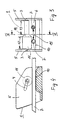
- the brake assembly is instead of a brake roller 2 Brake roller 11 is provided, which are also in slot slots 4 is stored.
- the brake roller 11 points in the axial direction in a first and second area 12 and 13 different Diameter on.
- the first area 12 is the Diameter of the brake roller 11 so dimensioned that in this first area 12 the distance between the outer circumference of the Brake roller 11 and the boundary wall 10 of the cable outlet opening 6 is smaller than the outer diameter of the cable 7.
- the roll diameter is in the second region 13 chosen so that in this area the distance between the Outer periphery of the brake roller 11 and the boundary wall 10 is larger than the outer diameter of the cable 7.
- Between the two areas 12 and 13 is marked by a slope 14 continuous transition from one to the other Diameter of the brake roller 11 created.
- the cable 7 can be by lateral Train, as indicated by a double arrow 15, either in the first or second area 12 or 13 of the Brake roller 11 are pulled. Since in the first area 12 Distance between the brake roller 11 and the boundary wall 10 is smaller than the outer cable diameter, the cable 7 consequently in this first area between the brake roller 11 and the boundary wall 10 is clamped and cannot be wound up. In contrast, the cable 7 in the second Pulled area 13, it can be wound up by the cable drum be since it is free between the brake roller 11 and the Boundary wall 10 can slide through.
- the different diameter ranges for clamping or the sliding of the cable 7 can also by means of a continuously across the axial width of the brake roller 11 changing diameter course can be achieved.
- the Brake roller 11 must then have one on one side Have diameter that there the distance between the Brake roller 11 and the boundary wall 10 smaller and on the other side is larger than the outer cable diameter.
Landscapes
- Storing, Repeated Paying-Out, And Re-Storing Of Elongated Articles (AREA)
- Braking Arrangements (AREA)
Description
- FIG 1
- die Bremsstellung einer Bremsanordnung, bei der eine Bremsrolle in Kulissenschlitzen gelagert ist, die im Anschluß an einen flachen Anstieg einen steilen Anstieg aufweisen,
- FIG 2
- die Lösestellung einer Bremsanordnung, bei der eine Bremsrolle in Kulissenschlitzen gelagert ist, die im Anschluß an einen flachen Anstieg einen steilen Anstieg aufweisen,
- FIG 3
- eine Bremsanordnung mit einer Bremswalze, die in Richtung ihrer Achse zwei Bereiche mit unterschiedlichen Walzendurchmessern aufweist und
- FIG 4
- eine Bremsanordnung im Schnitt entlang der Linie IV-IV in Fig.3.
Claims (2)
- Bremsanordnung für eine in einem Gehäuse, insbesondere Stausaugergehäuse, eingebaute, selbstaufwickelnde Kabeltrommel, welche Anordnung ein in einer im Gehäuse vorgesehenen Kabelauslaßöffnung (6) verstellbar angeordnetes und unter dem Einfluß der Aufwickelkraft eine Selbsthemmung bewirkendes Bremsglied (2) aufweist, dessen Bremswirkung zum Aufwickeln des Kabels (7) aufhebbar ist, dadurch gekennzeichnet, daß als Bremsglied eine mit ihren Achsenden beidseitig in Kulissenschlitzen (4) geführte Bremsrolle (2) vorgesehen ist, wobei die Kulissenschlitze (4) so gestaltet sind, daß die Bremsrolle (2) durch eine auf das Kabel (7) ausgeübte Zugkraft bewirkte Lageänderung des Kabels (7) in eine von ihrer in der Bremsstellung eingenommenen Lage abweichende Entriegelungsstellung bewegt und während des Aufwickelvorganges in dieser Entriegelungsstellung gehalten ist.
- Bremsanordnung nach Anspruch 1, dadurch gekennzeichnet, daß die Kulissenschlitze (4) in Bezug auf die Auszugsrichtung des Kabels (7) zunächst gering ansteigend verlaufen und anschließend steil nach oben geführt sind.
Applications Claiming Priority (2)
| Application Number | Priority Date | Filing Date | Title |
|---|---|---|---|
| DE19607146A DE19607146A1 (de) | 1996-02-26 | 1996-02-26 | Bremsanordnung für eine in einem Gehäuse eingebaute selbstaufwickelnde Kabeltrommel |
| DE19607146 | 1996-02-26 |
Publications (2)
| Publication Number | Publication Date |
|---|---|
| EP0791553A1 EP0791553A1 (de) | 1997-08-27 |
| EP0791553B1 true EP0791553B1 (de) | 2000-05-24 |
Family
ID=7786449
Family Applications (1)
| Application Number | Title | Priority Date | Filing Date |
|---|---|---|---|
| EP97101642A Expired - Lifetime EP0791553B1 (de) | 1996-02-26 | 1997-02-03 | Bremsanordnung für eine in einem Gehäuse eingebaute selbstaufwickelnde Kabeltrommel |
Country Status (3)
| Country | Link |
|---|---|
| EP (1) | EP0791553B1 (de) |
| DE (2) | DE19607146A1 (de) |
| ES (1) | ES2148848T3 (de) |
Families Citing this family (5)
| Publication number | Priority date | Publication date | Assignee | Title |
|---|---|---|---|---|
| DE10012457A1 (de) * | 2000-03-15 | 2001-09-20 | Adolf Wuerth Gmbh & Co Kg | Abrollgerät für Schläuche oder dergleichen |
| DE10142110A1 (de) * | 2001-08-30 | 2003-03-20 | Bsh Bosch Siemens Hausgeraete | Kabeltrommel |
| DE10335652A1 (de) | 2003-07-29 | 2005-02-24 | Hansgrohe Ag | Halterungsanordnung für eine Brause |
| DE102005018008B4 (de) * | 2005-04-18 | 2006-12-28 | Miele & Cie. Kg | Einbau-Kabeltrommel mit einem Aufwickelsystem für ein Anschlußkabel |
| CN110980437A (zh) * | 2019-11-29 | 2020-04-10 | 重庆文理学院 | 电气设备用线路整理装置 |
Family Cites Families (4)
| Publication number | Priority date | Publication date | Assignee | Title |
|---|---|---|---|---|
| BE424812A (de) * | ||||
| GB1275729A (en) * | 1968-12-06 | 1972-05-24 | Fisco Products Ltd | Improvements in extensible steel tape rules |
| DE2911506A1 (de) * | 1979-03-23 | 1980-09-25 | Siemens Ag | Bremsanordnung fuer eine in einem gehaeuse eingebaute kabeltrommel |
| DE8907658U1 (de) * | 1989-06-22 | 1990-11-08 | Siemens AG, 1000 Berlin und 8000 München | Kabelaufwickelvorrichtung |
-
1996
- 1996-02-26 DE DE19607146A patent/DE19607146A1/de not_active Withdrawn
-
1997
- 1997-02-03 ES ES97101642T patent/ES2148848T3/es not_active Expired - Lifetime
- 1997-02-03 DE DE59701742T patent/DE59701742D1/de not_active Expired - Fee Related
- 1997-02-03 EP EP97101642A patent/EP0791553B1/de not_active Expired - Lifetime
Also Published As
| Publication number | Publication date |
|---|---|
| DE59701742D1 (de) | 2000-06-29 |
| DE19607146A1 (de) | 1997-08-28 |
| EP0791553A1 (de) | 1997-08-27 |
| ES2148848T3 (es) | 2000-10-16 |
Similar Documents
| Publication | Publication Date | Title |
|---|---|---|
| EP2058253B1 (de) | Abrollvorrichtung für Wickelrollen | |
| DE3241924A1 (de) | Vorrichtung zum fuehren von flexiblen versorgungsleitungen | |
| EP2035263B1 (de) | Betätigungselement für die parksperre eines getriebes und parksperre für ein getriebe | |
| DE4241730A1 (de) | Federangetriebener Aufroller für Sicherheitsgurte bei Kraftfahrzeugen | |
| EP1740426B1 (de) | Rollosystem für ein fahrzeugdach | |
| EP1042104A1 (de) | Gliederschürze | |
| DE4315750C2 (de) | Aufhängevorrichtung und Verlegegerät für lineares Material wie beispielsweise Rohre und Kabel | |
| EP1450078B1 (de) | Schaltvorrichtung für ein automatisches Kraftfahrzeuggetriebe mit einer Sperrvorrichtung für den Wählhebel | |
| WO1999015754A1 (de) | Rolltor mit einem flexiblen torblatt | |
| EP0791553B1 (de) | Bremsanordnung für eine in einem Gehäuse eingebaute selbstaufwickelnde Kabeltrommel | |
| WO1995033909A1 (de) | Rollo oder dergleichen | |
| DE2932255A1 (de) | Einrichtung zum erfassen und halten des anschlussendes eines bandes in einer bandrolle | |
| EP0152909B1 (de) | Vorrichtung zum selbsttätigen Aufrollen eines Fahrzeugsicherheitsgurtes | |
| EP0004854A1 (de) | Verfahren zum Betrieb eines Walzband-Haspels sowie Walzband-Haspel zur Ausübung des Verfahrens | |
| AT403712B (de) | Kanalreinigungsfahrzeug | |
| DE19825479A1 (de) | Schaltvorrichtung für ein Fahrzeuggetriebe mit Verriegelungsmechanismus | |
| EP0050785B1 (de) | Parkblockiereinrichtung für ein Getriebe | |
| EP2025857B1 (de) | Führungsschiene zur Führung von Rollladenpanzern | |
| EP0669447A1 (de) | Sonnenschutzvorrichtung | |
| DE2800098C3 (de) | Abwickelvorrichtung für Warenbahnen in Form von Abwickelrollen | |
| EP0972689A2 (de) | Hubeinrichtung, insbesondere Sattelstütze | |
| EP0403878A1 (de) | Kabelaufwickelvorrichtung | |
| DE19817933A1 (de) | Seilführung | |
| DE3134765C2 (de) | Sattelkupplung | |
| DE3039202C2 (de) |
Legal Events
| Date | Code | Title | Description |
|---|---|---|---|
| PUAI | Public reference made under article 153(3) epc to a published international application that has entered the european phase |
Free format text: ORIGINAL CODE: 0009012 |
|
| AK | Designated contracting states |
Kind code of ref document: A1 Designated state(s): DE ES FR GB IT SE |
|
| 17P | Request for examination filed |
Effective date: 19980205 |
|
| RAP1 | Party data changed (applicant data changed or rights of an application transferred) |
Owner name: BSH BOSCH UND SIEMENS HAUSGERAETE GMBH |
|
| 17Q | First examination report despatched |
Effective date: 19980803 |
|
| GRAG | Despatch of communication of intention to grant |
Free format text: ORIGINAL CODE: EPIDOS AGRA |
|
| GRAG | Despatch of communication of intention to grant |
Free format text: ORIGINAL CODE: EPIDOS AGRA |
|
| GRAH | Despatch of communication of intention to grant a patent |
Free format text: ORIGINAL CODE: EPIDOS IGRA |
|
| GRAH | Despatch of communication of intention to grant a patent |
Free format text: ORIGINAL CODE: EPIDOS IGRA |
|
| GRAA | (expected) grant |
Free format text: ORIGINAL CODE: 0009210 |
|
| AK | Designated contracting states |
Kind code of ref document: B1 Designated state(s): DE ES FR GB IT SE |
|
| GBT | Gb: translation of ep patent filed (gb section 77(6)(a)/1977) |
Effective date: 20000524 |
|
| REF | Corresponds to: |
Ref document number: 59701742 Country of ref document: DE Date of ref document: 20000629 |
|
| ET | Fr: translation filed | ||
| ITF | It: translation for a ep patent filed | ||
| REG | Reference to a national code |
Ref country code: ES Ref legal event code: FG2A Ref document number: 2148848 Country of ref document: ES Kind code of ref document: T3 |
|
| PGFP | Annual fee paid to national office [announced via postgrant information from national office to epo] |
Ref country code: DE Payment date: 20010323 Year of fee payment: 5 |
|
| PLBE | No opposition filed within time limit |
Free format text: ORIGINAL CODE: 0009261 |
|
| STAA | Information on the status of an ep patent application or granted ep patent |
Free format text: STATUS: NO OPPOSITION FILED WITHIN TIME LIMIT |
|
| 26N | No opposition filed | ||
| REG | Reference to a national code |
Ref country code: GB Ref legal event code: IF02 |
|
| PGFP | Annual fee paid to national office [announced via postgrant information from national office to epo] |
Ref country code: GB Payment date: 20020128 Year of fee payment: 6 |
|
| PGFP | Annual fee paid to national office [announced via postgrant information from national office to epo] |
Ref country code: FR Payment date: 20020221 Year of fee payment: 6 Ref country code: ES Payment date: 20020221 Year of fee payment: 6 |
|
| PGFP | Annual fee paid to national office [announced via postgrant information from national office to epo] |
Ref country code: SE Payment date: 20020222 Year of fee payment: 6 |
|
| PG25 | Lapsed in a contracting state [announced via postgrant information from national office to epo] |
Ref country code: DE Free format text: LAPSE BECAUSE OF NON-PAYMENT OF DUE FEES Effective date: 20020903 |
|
| PG25 | Lapsed in a contracting state [announced via postgrant information from national office to epo] |
Ref country code: GB Free format text: LAPSE BECAUSE OF NON-PAYMENT OF DUE FEES Effective date: 20030203 |
|
| PG25 | Lapsed in a contracting state [announced via postgrant information from national office to epo] |
Ref country code: SE Free format text: LAPSE BECAUSE OF NON-PAYMENT OF DUE FEES Effective date: 20030204 Ref country code: ES Free format text: LAPSE BECAUSE OF NON-PAYMENT OF DUE FEES Effective date: 20030204 |
|
| GBPC | Gb: european patent ceased through non-payment of renewal fee | ||
| EUG | Se: european patent has lapsed | ||
| PG25 | Lapsed in a contracting state [announced via postgrant information from national office to epo] |
Ref country code: FR Free format text: LAPSE BECAUSE OF NON-PAYMENT OF DUE FEES Effective date: 20031031 |
|
| REG | Reference to a national code |
Ref country code: FR Ref legal event code: ST |
|
| REG | Reference to a national code |
Ref country code: ES Ref legal event code: FD2A Effective date: 20030204 |
|
| PG25 | Lapsed in a contracting state [announced via postgrant information from national office to epo] |
Ref country code: IT Free format text: LAPSE BECAUSE OF NON-PAYMENT OF DUE FEES Effective date: 20050203 |