EP0791121B1 - Mehrzweckkomplex - Google Patents
Mehrzweckkomplex Download PDFInfo
- Publication number
- EP0791121B1 EP0791121B1 EP96926666A EP96926666A EP0791121B1 EP 0791121 B1 EP0791121 B1 EP 0791121B1 EP 96926666 A EP96926666 A EP 96926666A EP 96926666 A EP96926666 A EP 96926666A EP 0791121 B1 EP0791121 B1 EP 0791121B1
- Authority
- EP
- European Patent Office
- Prior art keywords
- event
- stand
- complex
- ground
- floor part
- Prior art date
- Legal status (The legal status is an assumption and is not a legal conclusion. Google has not performed a legal analysis and makes no representation as to the accuracy of the status listed.)
- Expired - Lifetime
Links
- 238000006073 displacement reaction Methods 0.000 claims abstract description 15
- 239000000463 material Substances 0.000 claims description 7
- 229920001343 polytetrafluoroethylene Polymers 0.000 claims description 7
- 239000004810 polytetrafluoroethylene Substances 0.000 claims description 7
- -1 polytetrafluoroethylene Polymers 0.000 claims description 5
- 229910001220 stainless steel Inorganic materials 0.000 claims description 3
- 239000010935 stainless steel Substances 0.000 claims description 3
- 239000002783 friction material Substances 0.000 abstract description 2
- 238000010276 construction Methods 0.000 description 5
- 241000272470 Circus Species 0.000 description 4
- 210000005069 ears Anatomy 0.000 description 3
- XLYOFNOQVPJJNP-UHFFFAOYSA-N water Substances O XLYOFNOQVPJJNP-UHFFFAOYSA-N 0.000 description 3
- 238000011109 contamination Methods 0.000 description 2
- 239000007921 spray Substances 0.000 description 2
- 239000004809 Teflon Substances 0.000 description 1
- 229920006362 Teflon® Polymers 0.000 description 1
- 229920006333 epoxy cement Polymers 0.000 description 1
- 239000007788 liquid Substances 0.000 description 1
- 239000000314 lubricant Substances 0.000 description 1
- 239000002184 metal Substances 0.000 description 1
- 229920001296 polysiloxane Polymers 0.000 description 1
- 238000002360 preparation method Methods 0.000 description 1
- 239000012791 sliding layer Substances 0.000 description 1
Images


Classifications
-
- E—FIXED CONSTRUCTIONS
- E01—CONSTRUCTION OF ROADS, RAILWAYS, OR BRIDGES
- E01C—CONSTRUCTION OF, OR SURFACES FOR, ROADS, SPORTS GROUNDS, OR THE LIKE; MACHINES OR AUXILIARY TOOLS FOR CONSTRUCTION OR REPAIR
- E01C13/00—Pavings or foundations specially adapted for playgrounds or sports grounds; Drainage, irrigation or heating of sports grounds
- E01C13/08—Surfaces simulating grass ; Grass-grown sports grounds
- E01C13/083—Construction of grass-grown sports grounds; Drainage, irrigation or heating arrangements therefor
-
- E—FIXED CONSTRUCTIONS
- E04—BUILDING
- E04H—BUILDINGS OR LIKE STRUCTURES FOR PARTICULAR PURPOSES; SWIMMING OR SPLASH BATHS OR POOLS; MASTS; FENCING; TENTS OR CANOPIES, IN GENERAL
- E04H3/00—Buildings or groups of buildings for public or similar purposes; Institutions, e.g. infirmaries or prisons
- E04H3/10—Buildings or groups of buildings for public or similar purposes; Institutions, e.g. infirmaries or prisons for meetings, entertainments, or sports
- E04H3/14—Gymnasiums; Other sporting buildings
-
- E—FIXED CONSTRUCTIONS
- E01—CONSTRUCTION OF ROADS, RAILWAYS, OR BRIDGES
- E01C—CONSTRUCTION OF, OR SURFACES FOR, ROADS, SPORTS GROUNDS, OR THE LIKE; MACHINES OR AUXILIARY TOOLS FOR CONSTRUCTION OR REPAIR
- E01C13/00—Pavings or foundations specially adapted for playgrounds or sports grounds; Drainage, irrigation or heating of sports grounds
- E01C2013/006—Transportable sport surfaces for multipurpose stadiums
Definitions
- the invention relates to an event complex provided with at least one event surface and one or more stands at least partially surrounding the event surface, at least one of which stands is slidable relative to the event surface over slide elements arranged between the stand and a ground and at least during sliding having low friction.
- an event complex which can take for instance the form of a sports stadium is known from US-A-4,688,357 and compared with event complexes with fixed stands offers the advantage that the event complex can be used for a variety of purposes.
- By displacing one of the stands toward or away from a stand located opposite the complex can be made suitable for smaller-scale or larger-scale events than those for which it was basically designed.
- a football stadium may be transformed into a baseball stadium by displacing part of the stands.
- a stadium having displaceable stands offers a variety of possible stand locations for a large number of events.
- By moving inward the stands to form a so-called arena arrangement for instance a football stadium can thus be made suitable for instance for a boxing match or a small-scale concert, while, conversely, by moving the same part of the stand outward it becomes suitable for instance for circus performances or exhibitions. It has been found that the thus obtained flexibility in terms of use is an economic condition for a responsible operation of a large-scale event complex.
- the known event complex with displaceable stands has a displacement system using rubber bags located under the displaceable stands and not being completely tight. Before displacing these bags are filled with water, which subsequently leaks from the bags thus forming a thin sliding layer.
- this known system has the advantage that when the stand assumes its position moved furthest to the outside, no guide rails lie exposed in the event surface which would have to be covered. In the stadium as known from the cited US patent on the other hand, the event surface is completely free of obstacles after the stand or stands have been moved.
- the known event complex has the drawback that the slide elements are not slidable in themselves, and prior to moving of the stand or stands must be filled with water, which then leaks away during moving. Therefore, moving the stands is relatively complicated, whereas after moving the event complex always has to be cleared of the water that has been used as a lubricant.
- the invention now has for its object to provide an event complex of the above described type wherein this drawback does not occur.
- the slide elements comprise a material with low friction, like e.g. polytetrafluoroethylene, and in that each slide element forms an endless belt which is guided over reversing rollers and a transporting part of which is located between the stand and the ground and a return part of which is guided through the stand or the ground.
- the stand may be slid about without complicated preparations or further treatment.
- DE-A-28 52 181 a stand for a sports hall is known, which consists of a plurality of rows of benches which may be telescopically slid under one another, and which are provided on their undersides with slide elements made of a low friction material like e.g. TeflonTM (PTFE).
- PTFE TeflonTM
- the event complex comprises drive means arranged between the displaceble stand and the ground and formed by at least one piston/cylinder combination mounted on the stand or the ground, and a plurality of push-off points connected to the ground or the stand, co-acting with the free outer end of the pistons and arranged with interspaces in the displacement direction. In this way the stand may be easily moved between its various positions.
- the event complex also comprises at least one floor part arranged on the event surface and displacable relative to the fixed stand parts.
- the flexibility of the event complex is further enhanced. It is preferred that the displacement of the floor part be effected by slide elements of the same type as used for displacing the stands, e.g. slide elements in the form of endless belts.
- the event complex may also comprise a furhter set of drive means for moving the floor part, which drive means are preferably simmilar for those used for moving the stand.
- the invention also relates to a slide element for use in a stand for an event complex as described above, in addition to drive means for use therein.
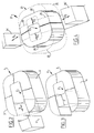
- An event complex 1 (fig. 1) comprises an event surface 2, in the shown example a football field, and a plurality of stands 3 wholly or partially enclosing this event surface 2.
- the stands consist herein of a number of fixed stands 4, in this case placed substantially in a U-shape and a stand 5 which is displaceable as according to arrow D relative to event surface 2.
- By moving the stand 5 in the direction of the stand located opposite a so-called arena arrangement is obtained which is particularly suitable for small-scale events.
- Such an arrangement ensures that all spectators have a good view of the event, also in the case of small-scale events such as for instance a boxing match or the like.
- displacing stand 5 provides access for large units such as circus material, boats for exhibition and the like.
- Fig. 2 and 3 show the displaceable stand respectively in its position 5" slid fully outward for special events to be held in stadium 3 and its position 5' slid fully inward for smaller-scale events.
- the stands 23 consists of two substantially U-shaped main stands 25' slidable toward each other according to arrows D1, D2 and two intermediate stands 24 slidable away from each other according to arrows D3 and D4.
- a comparatively small stadium is also obtained which, because both U-shaped stands 25 are moved against each other, moreover has more usable places than when only a part of the stand is displaced inward.
- the outward displaced stands 24' could serve as stand for smaller events taking place outside stadium 21.
- the stand 5 is slidable over a ground 6 located outside the actual event surface 2, respectively 22.
- slide elements 8 Arranged for this purpose between the ground 6 and a base 7 of the slidable stand 5 are slide elements 8 (fig. 5) which are manufactured from or at least coated with a material with low friction, such as for instance polytetrafluoroethylene (PTFE, known under the brand name Teflon).
- PTFE polytetrafluoroethylene
- Teflon polytetrafluoroethylene
- a metal strip 11 in a rubber sleeve 12 is arranged in the base 7 of the displaceable stand 5, to which sleeve the slide element 8 is fixed.
- the slide elements 8 are separate elements which can be removed after shifting of stand part 5 in order to keep the ground 6 also free of obstacles. Such separate slide elements could of course also be placed without problem on the event surface 2 itself.
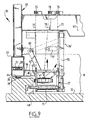
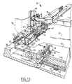
- a stand 35 of the event complex 31 displaceable (fig. 7) but also a floor part 42 arranged on event surface 32.
- the stand 35 is herein displaceable over an edge 36 which surrounds the event surface 32, while floor part 42 is displaceable over the event surface 32 itself.
- Stand 35 is formed by a bridge construction 40 suspended with posts 39 between two staircases 34 and embodied as a framework. Posts 39 are herein further connected by beams 41.
- the stand construction 35 is arranged on two base parts or supports 37 which are placed under the staircases 34 and which are displaceable over edges 36 with interposing of the slide elements 38.
- first drive means 47 are further arranged which co-act with push-off points or recesses 48 arranged in the foot of edge 36.
- guide means 76 are further arranged which likewise co-act with edge 36 and which for instance prevent possible tilting of stand 35.
- the displaceable floor part 42 which consists of a concrete tray 43 and a playing or sports field 44 accommodated therein, is displaceable over the slide elements 45 by second drive means 46 which are arranged in recesses 66 on the side of tray 43 and which likewise co-act with the push-off recesses 48 arranged in the edge 36.
- the slide elements 38 and 45 are each formed in this embodiment by an endless belt which is guided over reversing rollers 49 respectively 50 (fig. 8, 10), and the transporting part of which is located respectively between the base 37 of stand 35 and edge 36 and between the floor part 42 and the event surface 32.
- the return part is herein carried through a guide path 51 respectively 52 arranged in the base 37 of stand 35 respectively in the bottom of the tray 43 of the slidable floor part 42.
- the reversing rollers 49 respectively 50 are rotatable round a shaft 55 respectively 56 arranged in a guide frame 57 respectively 58.
- Guide frame 57, 58 is spring-mounted and is mounted pivotally on the base 37 respectively the tray 43 at pivot points 53 respectively 93.
- a spray nozzle 61 is furthermore present from which a silicone liquid is dripped onto slide elements 38 respectively 45 to further reduce the resistance thereof.
- a brush 62 is also present to keep the ground 36 respectively 38 for the slide elements 38 respectively 45 free of contamination.
- the spray nozzle 61 and the brush 62 are omitted in fig. 8 for the sake of clarity of the illustration.
- An additional guide roller 63 is further arranged in tray 43 in order to limit the construction height as far as possible and still enable use of a relatively large reversing roller 50.
- the slide elements 38 respectively 45 further co-act with stainless steel slide tracks 64 respectively 65 which are arranged on the underside of the support 37 and the tray 43 respectively.
- the stand 35 and the floor part 42 are in fact self-propelling over the ground 36 respectively the event surface 32.
- the event surface 32 and the ground 36 can therefore be manufactured in simple manner from smoothly finished concrete without for instance slide plates having to be cast therein.
- the slide elements as shown in fig. 5 and 6 could of course also be applied in this embodiment of the event complex, wherein use would then in any case have to be made of separate slide elements 8 for the floor part 42.
- the stand 35 or the floor part 42 only need to be slidable along a straight line, it is possible to use endless belts 38, 45 extending over substantially the entire length of the stand 35, or the floor part 42 respectively.
- endless belts 38, 45 extending over substantially the entire length of the stand 35, or the floor part 42 respectively.
- it is desirable for the stand or the floor part to be able to perform a nonlinear movement, for instance a pivoting movement use is preferably made of a plurality of relatively short length belts 138 or 145 respectively, which are arranged behind one another in the direction of sliding, and which might be constructed such as to be somewhat displaceable or pivotable perpendicular to the direction of sliding (fig. 14).
- a greater freedom of displacement is obtained so that the event complex may for instance be transformed from a football stadium into a baseball stadium.
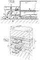
- the means 46 for driving floor part 42 comprise a plurality of piston/cylinder combinations 67 which are arranged in the recesses 66 on the side of tray 43 and which are movable and displaceable in a horizontal plane and which co-act with the push-off recesses 48 in the edge 36.
- the piston/cylinder combinations 67 are provided on the free outer end of their piston 68 with a push-off part which can be placed against an end wall of the push-off recesses 48 and can push off thereagainst.
- Floor part 42 has a plurality of such sets of piston/cylinder combinations 67, 69 which are fixed to floor part 42 in two opposing directions in order to enable a displacement of floor part 42 in two directions.
- Floor part 42 is further provided with guide means arranged on its corners in the form of wheel sets 70 which run along the edges 36 and thus ensure an even movement of floor part 42.
- the displaceable stand 35 is provided with drive means, likewise in the form of main piston/cylinder combinations 71 and auxiliary piston/cylinder combinations 72 (fig. 8).
- These piston/cylinder combinations 71 co-act with the same push-off recesses 48 as the piston/cylinder combinations 67 of floor part 42.
- these piston/cylinder combinations 71 are accommodated in a retractable auxiliary frame 73 with a guide leg 75 which is suspended with cables 77 from a transverse beam 41 of stand 35 and which is displaceable up and downward by means of two winches 74 (fig. 9).
- the supports 37 are each provided with ears 96 which co-act with a leg 95 of auxiliary frame 73 when this latter is lowered. Leg 95 and ears 96 are herein connected by a releasable locking pin 97.
- the auxiliary frame 73 further has supports 94 which rest against the support 37 in the lowered position.
- the stand 35 also comprises guide means in the form of wheel sets 76 to ensure an even displacement thereof along edges 36.
- These wheel sets 76 are likewise retractable by means of a winch 78 and a cable 79, wherein the wheel set 76 is then pivoted upward round a pivot shaft 80 connected to the frame of stand 35. Locking of the wheel sets takes place in the same manner as the above described taking up of the reactive forces by means of ears and a detachable locking pin, which are not drawn here for the sake of clarity. In this manner the drive of stand 35 can be raised when floor part 42 must be displaced and the stand 35 can be displaced when floor part 42 is shifted by lowering the drive 47.
- both stand 35 and floor part 42 are self-sliding over the endless slide elements 38, 45 arranged therein and the driving takes place via push-off recesses arranged in the side wall of the standing edge 36, after displacing of stand 35 or floor part 42 there remains an event surface 32 with edge 36 which is wholly free of obstacles.
- the utility of the event surface 32 and therewith the whole event complex is hereby greatly increased.
- guide means in the form of wheel sets 70, 76 it is of course also possible to use a guide system with which there is no direct contact between the guide means and the guide track or edge co-acting therewith. This may be important in case there is no room for placing such a guide edge.
- an electronic guide system may for instance be used, in which the position of the movable floor part 42 or the movable stand 35 vis-à-vis a reference plane or line is determined by means of sensors 170, 176, and the drive means 46, 71 and 72 respectively are controlled on the basis of the position thus determined, so as to be able to carry out corrective action if necessary (fig. 13).
- the drive cylinders 67 and 71 respectively on both sides may thus make varying strokes, whereby the floor part 42 or the stand 35 is again precisely aligned.
- the distance measuring sensors 170, 176 it is of course also possible to use a guide system on the basis of for instance laser beams directed in the direction of movement, which are interrupted in case of diversions from the intended direction of displacement, whereby a correcting control signal is generated.
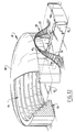
- the slidable stand 85 is considerably smaller than the surrounding fixed stans 84.
- a projection screen 86 is for instance arranged herein above the displaceable stand 85.
- the stand 85 is slidable not only inward but also outward, whereby a large opening 87 is created in the wall of complex 81.
- the complex hereby becomes suitable for use as for instance circus. Since in the outward displaced position the stand 85 no longer contributes toward absorbing the structural loads resulting for instance from the weight of the roof 88, a support construction 89 is arranged round the opening 87 formed by two portals 90 leaning against each other.
- the stand 85 can also serve in its outward displaced position as small stand for events outside complex 81.
- the displaceable stand in combination with the displaceable floor part is described as being slidable over for instance slide elements, it will be apparent to the skilled person that in principle all kinds of other displacement options may be deemed suitable for the floor part.
- the floor part could be embodied for displacement in for instance vertical instead of horizontal direction, as described for instance in the Belgian patent application 9200094.
- the drive means, guide means and slide elements described here may also be suitable for other applications. Envisaged here for instance is the transport of very heavy construction parts on a building site.
Landscapes
- Engineering & Computer Science (AREA)
- Architecture (AREA)
- Civil Engineering (AREA)
- Structural Engineering (AREA)
- Organic Low-Molecular-Weight Compounds And Preparation Thereof (AREA)
- Floor Finish (AREA)
- Road Paving Structures (AREA)
- Invalid Beds And Related Equipment (AREA)
- Orthopedics, Nursing, And Contraception (AREA)
- Finger-Pressure Massage (AREA)
- Professional, Industrial, Or Sporting Protective Garments (AREA)
- Handcart (AREA)
- Transmission Devices (AREA)
Claims (22)
- Veranstaltungskomplex (1; 21; 31; 81), der mit zumindest einer Veranstaltungsfläche (2; 22; 32; 82; 132) sowie mit einer oder mehreren Tribünen versehen ist, die die Veranstaltungsfläche (2; 22; 32; 82; 132) zumindest teilweise umgeben, wobei zumindest eine Tribüne (5; 25; 35; 85; 135) der betreffenden Tribünen relativ zu der Veranstaltungsfläche (2; 22; 32; 82; 132) über Gleitelemente (8; 38; 138) verschiebbar ist, die zwischen der Tribüne (5; 25; 35; 135) und einem Boden (6; 36; 136) angeordnet sind und die zumindest während des Verschiebens bzw. Gleitens eine geringe Reibung aufweisen, dadurch gekennzeichnet, dass die Gleitelemente (8; 38; 138) ein Material mit geringer Reibung, wie beispielsweise Polytetrafluoräthylen, aufweisen
und dass jedes Gleitelement (38; 138) ein endloses Band bildet, welches über Umkehrrollen (49; 149) geführt ist und von dem ein Transportteil zwischen der Tribüne (35; 135) und dem Boden (36; 136) liegt und von dem ein Rückführteil durch die Tribüne (35; 135) oder den Boden (36; 136) geführt ist. - Veranstaltungskomplex (1; 21; 31; 81) nach Anspruch 1, dadurch gekennzeichnet, dass die Tribüne (35; 135) oder der Boden (36; 136) zumindest eine Führungsbahn (51) für den Rückführteil aufweist, die mit einem Material mit geringer Reibung überzogen ist.
- Veranstaltungskomplex (1; 21; 31; 81) nach Anspruch 1 oder 2, dadurch gekennzeichnet, dass die Gleitelemente (38; 138) zumindest eine Gleitschicht aus Polytetrafluoräthylen aufweisen.
- Veranstaltungskomplex (1; 21; 31; 81) nach irgendeinem der vorhergehenden Ansprüche, dadurch gekennzeichnet, dass Gleitschienen (65) vorgesehen sind, die aus einem verschleißfesten Material hergestellt sind und die mit den Gleitelementen (38; 138) zusammenwirken.
- Veranstaltungskomplex (1; 21; 31; 81) nach Anspruch 4, dadurch gekennzeichnet, dass die Gleitschienen (65) aus rostfreiem Stahl hergestellt sind.
- Veranstaltungskomplex (1; 21; 31; 81) nach irgendeinem der vorhergehenden Ansprüche, dadurch gekennzeichnet, dass erste Antriebseinrichtungen (47) vorgesehen sind, die zwischen der verschiebbaren Tribüne (35) und dem Boden (36) angeordnet sind und die durch zumindest eine Kolben-/Zylinderkombination (71), die an der Tribüne (35) oder auf dem Boden (36) angeordnet ist, und eine Vielzahl von Abdrückpunkten (48) gebildet ist, die mit dem Boden (36) oder der Tribüne (35) verbunden sind, und die mit dem freien äußeren Ende der Kolben (71) zusammenwirken und mit Zwischenräumen in der Verschieberichtung angeordnet sind.
- Veranstaltungskomplex (1; 21; 31; 81) nach Anspruch 6, dadurch gekennzeichnet, dass zumindest eine Kolben-/Zylinderkombination (71) an der Tribüne (35) angebracht ist und dass die Abdrückpunkte (48) durch Ausnehmungen gebildet sind, die im Boden (36) angeordnet sind.
- Veranstaltungskomplex (1; 21; 31; 81) nach Anspruch 6 oder 7, dadurch gekennzeichnet, dass Führungseinrichtungen (76) vorgesehen sind, die steuerbar mit den ersten Antriebseinrichtungen (47) verbunden sind.
- Veranstaltungskomplex (1; 21; 31; 81) nach irgendeinem der vorhergehenden Ansprüche, dadurch gekennzeichnet, dass die Tribüne (5; 25; 35; 85; 135) von der gegenüberliegenden Tribüne weg in eine Position außerhalb des Umfangs verschiebbar ist, der durch die festen Tribünen (4; 24; 84) festgelegt ist.
- Veranstaltungskomplex (1; 21; 31; 81) nach irgendeinem der vorhergehenden Ansprüche, dadurch gekennzeichnet, dass die Tribüne (5; 25; 35; 85; 135) in Richtung der gegenüberliegenden Tribüne verschiebbar ist.
- Veranstaltungskomplex (1; 21; 31; 81) nach irgendeinem der vorhergehenden Ansprüche, dadurch gekennzeichnet, dass die Tribüne (5; 25; 35; 85; 135) schwenkbar ist.
- Veranstaltungskomplex (1; 21; 31; 81) nach irgendeinem der vorhergehenden Ansprüche, dadurch gekennzeichnet, dass zumindest ein Bodenteil (42; 142) auf der Veranstaltungsfläche (32; 132) angeordnet und relativ zu den festen Tribünenteilen verschiebbar ist.
- Veranstaltungskomplex (1; 21; 31; 81) nach Anspruch 12, dadurch gekennzeichnet, dass zumindest ein Bodenteil (42; 142) ein Sportfeld (44) bildet.
- Veranstaltungskomplex (1; 21; 31; 81) nach Anspruch 12 oder 13, dadurch gekennzeichnet, dass der Bodenteil (42; 142) über Gleitelemente (45; 145) verschiebbar ist, die zwischen dem Bodenteil (42; 142) und der Veranstaltungsfläche (32; 132) angeordnet sind und die ein Material geringer Reibung, wie beispielsweise Polytetrafluoräthylen, aufweisen.
- Veranstaltungskomplex (1; 21; 31; 81) nach Anspruch 14, dadurch gekennzeichnet, dass jedes Gleitelement (45; 145) ein endloses Band bildet, welches über Umkehrrollen (50; 150) geführt ist und von dem ein Transportteil zwischen dem Bodenteil (42; 142) und der Veranstaltungsfläche (32; 132) liegt und von dem ein Rückführteil durch den Bodenteil (42; 142) oder die Veranstaltungsfläche (32; 132) geführt ist.
- Veranstaltungskomplex (1; 21; 31; 81) nach irgendeinem der Ansprüche 12 bis 15, dadurch gekennzeichnet, dass zweite Antriebseinrichtungen (46) zwischen dem Bodenteil (42) und der Veranstaltungsfläche (32) angeordnet und durch zumindest eine Kolben-/Zylinderkombination (67, 68) gebildet sind, die an dem Bodenteil (42) oder der Veranstaltungsfläche (32) angebracht ist, und eine Vielzahl von Abdrückpunkten (48) aufweist, die mit der Veranstaltungsfläche (32) oder dem Bodenteil (42) verbunden sind und die mit dem freien äußeren Ende des Kolbens (68) zusammenwirken und mit Zwischenräumen in der Verschieberichtung angeordnet sind.
- Veranstaltungskomplex (1; 21; 31; 81) nach Anspruch 16, dadurch gekennzeichnet, dass zumindest eine Kolben-/Zylinderkombination (67, 68) auf bzw. an dem Bodenteil (42) angebracht ist und dass die Abdrückpunkte (48) durch Ausnehmungen gebildet sind, die im Boden (36) gebildet sind, der außerhalb der Veranstaltungsfläche (32) liegt.
- Veranstaltungskomplex (1; 21; 31; 81) nach Anspruch 16 oder 17, dadurch gekennzeichnet, dass Führungseinrichtungen (70) vorgesehen sind, die mit den zweiten Antriebseinrichtungen (46) steuerbar verbunden sind.
- Veranstaltungskomplex (1; 21; 31; 81) nach Anspruch 7 und 17 oder 18, dadurch gekennzeichnet, dass entweder die Kolben-/Zylinderkombination (71; 67; 68), die an der Tribüne (35) oder an dem Bodenteil (42) befestigt ist, rückziehbar ist und dass beide Kolben-/Zylinderkombinationen (71; 67; 68) mit demselben Satz von Ausnehmungen (48) im Boden (36) zusammenwirken.
- Veranstaltungskomplex (1; 21; 31; 81) nach Anspruch 12 oder 13, dadurch gekennzeichnet, dass der Bodenteil (42) in vertikaler Richtung bezogen auf die Veranstaltungsfläche (32) verschiebbar ist.
- Gleitelement (38; 35; 138; 145), welches offensichtlich vorgesehen ist für die Verwendung in einem Veranstaltungskomplex (1; 21; 31; 81) nach einem oder mehreren der vorhergehenden Ansprüche.
- Antriebseinrichtung (46; 47), die offensichtlich vorgesehen ist für die Verwendung in einem Veranstaltungskomplex (1; 21; 31; 81) nach einem oder mehreren der Ansprüche 1 bis 20.
Applications Claiming Priority (3)
| Application Number | Priority Date | Filing Date | Title |
|---|---|---|---|
| NL1001000 | 1995-08-17 | ||
| NL1001000A NL1001000C2 (nl) | 1995-08-17 | 1995-08-17 | Manifestatiecomplex. |
| PCT/NL1996/000328 WO1997007306A1 (en) | 1995-08-17 | 1996-08-19 | Event complex |
Publications (2)
| Publication Number | Publication Date |
|---|---|
| EP0791121A1 EP0791121A1 (de) | 1997-08-27 |
| EP0791121B1 true EP0791121B1 (de) | 2001-05-09 |
Family
ID=19761450
Family Applications (1)
| Application Number | Title | Priority Date | Filing Date |
|---|---|---|---|
| EP96926666A Expired - Lifetime EP0791121B1 (de) | 1995-08-17 | 1996-08-19 | Mehrzweckkomplex |
Country Status (9)
| Country | Link |
|---|---|
| EP (1) | EP0791121B1 (de) |
| JP (1) | JPH10508072A (de) |
| AT (1) | ATE201079T1 (de) |
| AU (1) | AU6671896A (de) |
| DE (1) | DE69612729T2 (de) |
| ES (1) | ES2156286T3 (de) |
| NL (1) | NL1001000C2 (de) |
| PT (1) | PT791121E (de) |
| WO (1) | WO1997007306A1 (de) |
Families Citing this family (2)
| Publication number | Priority date | Publication date | Assignee | Title |
|---|---|---|---|---|
| NL1006958C2 (nl) * | 1997-09-05 | 1999-03-11 | Hollandsche Betongroep Nv | Evenementen-bouwwerk met verplaatsbaar veld. |
| WO1999032724A1 (de) * | 1997-12-18 | 1999-07-01 | Schiess-Defries Engineering Immobilien- Und Bauträger Gmbh | Unterkonstruktion für bauwerke |
Citations (1)
| Publication number | Priority date | Publication date | Assignee | Title |
|---|---|---|---|---|
| BE1006660A5 (nl) * | 1992-01-30 | 1994-11-08 | Ballast Nedam Eng | Manifestatiecomplex. |
Family Cites Families (3)
| Publication number | Priority date | Publication date | Assignee | Title |
|---|---|---|---|---|
| US3975869A (en) * | 1974-11-18 | 1976-08-24 | James Bouton | Sports complex |
| US4688357A (en) * | 1986-04-16 | 1987-08-25 | Deaton Charles U | Multi-purpose stadium system |
| NL192577B (nl) * | 1991-09-16 | 1997-06-02 | Rudolphus Johannes Christiaan | Sportaccomodatie. |
-
1995
- 1995-08-17 NL NL1001000A patent/NL1001000C2/nl not_active IP Right Cessation
-
1996
- 1996-08-19 AT AT96926666T patent/ATE201079T1/de not_active IP Right Cessation
- 1996-08-19 JP JP9509181A patent/JPH10508072A/ja active Pending
- 1996-08-19 AU AU66718/96A patent/AU6671896A/en not_active Abandoned
- 1996-08-19 EP EP96926666A patent/EP0791121B1/de not_active Expired - Lifetime
- 1996-08-19 DE DE69612729T patent/DE69612729T2/de not_active Expired - Fee Related
- 1996-08-19 WO PCT/NL1996/000328 patent/WO1997007306A1/en not_active Ceased
- 1996-08-19 PT PT96926666T patent/PT791121E/pt unknown
- 1996-08-19 ES ES96926666T patent/ES2156286T3/es not_active Expired - Lifetime
Patent Citations (1)
| Publication number | Priority date | Publication date | Assignee | Title |
|---|---|---|---|---|
| BE1006660A5 (nl) * | 1992-01-30 | 1994-11-08 | Ballast Nedam Eng | Manifestatiecomplex. |
Also Published As
| Publication number | Publication date |
|---|---|
| JPH10508072A (ja) | 1998-08-04 |
| AU6671896A (en) | 1997-03-12 |
| NL1001000C2 (nl) | 1997-02-18 |
| PT791121E (pt) | 2001-09-28 |
| EP0791121A1 (de) | 1997-08-27 |
| DE69612729D1 (de) | 2001-06-13 |
| ES2156286T3 (es) | 2001-06-16 |
| ATE201079T1 (de) | 2001-05-15 |
| DE69612729T2 (de) | 2002-02-07 |
| WO1997007306A1 (en) | 1997-02-27 |
Similar Documents
| Publication | Publication Date | Title |
|---|---|---|
| US3891062A (en) | Telescopic lift for construction works | |
| US7395900B2 (en) | Portable wheelchair lift | |
| EP1967784A2 (de) | Verbessertes Leitungs- und Seilsystem sowie Verfahren zur Bewegung eines Objekts durch einen dreidimensionalen Raum | |
| NL192123C (nl) | Manifestatiecomplex. | |
| FI88668B (fi) | Arrangemang foer foerflyttbart uppbaerande av moebler | |
| US6155022A (en) | Shielding panel removal and installation system for supportless dasher boards | |
| EP0791121B1 (de) | Mehrzweckkomplex | |
| US5762152A (en) | Movable conveyor | |
| CA2524128A1 (en) | Scaffolding structure | |
| CN215889402U (zh) | 一种组装式重力移动型卸料平台 | |
| WO1995033890A1 (en) | Utility surface | |
| US8256986B2 (en) | Machine for paving concrete paths | |
| RU2385980C1 (ru) | Мостовой механизированный комплекс | |
| JPH07259349A (ja) | 移動装置 | |
| RU2644373C2 (ru) | Сооружение для спортивно-концертных мероприятий | |
| NL2000658C2 (nl) | Inrichting en werkwijze voor het transporteren en positioneren van bestratingselementen. | |
| RU161988U1 (ru) | Выдвижное футбольное поле для крытого стадиона | |
| CN209261300U (zh) | 一种双柱龙门式简易升降泊车设备 | |
| WO2016137358A1 (ru) | Сооружение для спортивно-концертных мероприятий | |
| CN116815629B (zh) | 上弦爬拱检查车 | |
| JP2876973B2 (ja) | 全天候型施工システム | |
| JP3225308B2 (ja) | ハングアップ工法用揚体水平位置調整装置 | |
| SU685794A1 (ru) | Сцена зрительного зала | |
| SU163083A1 (de) | ||
| RU96893U1 (ru) | Многофункциональный стадион |
Legal Events
| Date | Code | Title | Description |
|---|---|---|---|
| PUAI | Public reference made under article 153(3) epc to a published international application that has entered the european phase |
Free format text: ORIGINAL CODE: 0009012 |
|
| 17P | Request for examination filed |
Effective date: 19970403 |
|
| AK | Designated contracting states |
Kind code of ref document: A1 Designated state(s): AT DE ES GB NL PT SE |
|
| 17Q | First examination report despatched |
Effective date: 19981112 |
|
| GRAG | Despatch of communication of intention to grant |
Free format text: ORIGINAL CODE: EPIDOS AGRA |
|
| GRAG | Despatch of communication of intention to grant |
Free format text: ORIGINAL CODE: EPIDOS AGRA |
|
| 17Q | First examination report despatched |
Effective date: 19981112 |
|
| GRAG | Despatch of communication of intention to grant |
Free format text: ORIGINAL CODE: EPIDOS AGRA |
|
| GRAG | Despatch of communication of intention to grant |
Free format text: ORIGINAL CODE: EPIDOS AGRA |
|
| GRAG | Despatch of communication of intention to grant |
Free format text: ORIGINAL CODE: EPIDOS AGRA |
|
| GRAG | Despatch of communication of intention to grant |
Free format text: ORIGINAL CODE: EPIDOS AGRA |
|
| GRAH | Despatch of communication of intention to grant a patent |
Free format text: ORIGINAL CODE: EPIDOS IGRA |
|
| GRAH | Despatch of communication of intention to grant a patent |
Free format text: ORIGINAL CODE: EPIDOS IGRA |
|
| GRAA | (expected) grant |
Free format text: ORIGINAL CODE: 0009210 |
|
| AK | Designated contracting states |
Kind code of ref document: B1 Designated state(s): AT DE ES GB NL PT SE |
|
| REF | Corresponds to: |
Ref document number: 201079 Country of ref document: AT Date of ref document: 20010515 Kind code of ref document: T |
|
| REF | Corresponds to: |
Ref document number: 69612729 Country of ref document: DE Date of ref document: 20010613 |
|
| REG | Reference to a national code |
Ref country code: ES Ref legal event code: FG2A Ref document number: 2156286 Country of ref document: ES Kind code of ref document: T3 |
|
| PGFP | Annual fee paid to national office [announced via postgrant information from national office to epo] |
Ref country code: PT Payment date: 20010727 Year of fee payment: 6 |
|
| PGFP | Annual fee paid to national office [announced via postgrant information from national office to epo] |
Ref country code: GB Payment date: 20010730 Year of fee payment: 6 |
|
| PG25 | Lapsed in a contracting state [announced via postgrant information from national office to epo] |
Ref country code: SE Free format text: LAPSE BECAUSE OF NON-PAYMENT OF DUE FEES Effective date: 20010820 Ref country code: ES Free format text: LAPSE BECAUSE OF NON-PAYMENT OF DUE FEES Effective date: 20010820 |
|
| PGFP | Annual fee paid to national office [announced via postgrant information from national office to epo] |
Ref country code: AT Payment date: 20010830 Year of fee payment: 6 |
|
| PGFP | Annual fee paid to national office [announced via postgrant information from national office to epo] |
Ref country code: NL Payment date: 20010831 Year of fee payment: 6 Ref country code: DE Payment date: 20010831 Year of fee payment: 6 |
|
| REG | Reference to a national code |
Ref country code: PT Ref legal event code: SC4A Free format text: AVAILABILITY OF NATIONAL TRANSLATION Effective date: 20010705 |
|
| REG | Reference to a national code |
Ref country code: GB Ref legal event code: IF02 |
|
| PLBE | No opposition filed within time limit |
Free format text: ORIGINAL CODE: 0009261 |
|
| STAA | Information on the status of an ep patent application or granted ep patent |
Free format text: STATUS: NO OPPOSITION FILED WITHIN TIME LIMIT |
|
| EUG | Se: european patent has lapsed |
Ref document number: 96926666.7 |
|
| 26N | No opposition filed | ||
| PG25 | Lapsed in a contracting state [announced via postgrant information from national office to epo] |
Ref country code: GB Free format text: LAPSE BECAUSE OF NON-PAYMENT OF DUE FEES Effective date: 20020819 Ref country code: AT Free format text: LAPSE BECAUSE OF NON-PAYMENT OF DUE FEES Effective date: 20020819 |
|
| PG25 | Lapsed in a contracting state [announced via postgrant information from national office to epo] |
Ref country code: PT Free format text: LAPSE BECAUSE OF NON-PAYMENT OF DUE FEES Effective date: 20030228 |
|
| PG25 | Lapsed in a contracting state [announced via postgrant information from national office to epo] |
Ref country code: NL Free format text: LAPSE BECAUSE OF NON-PAYMENT OF DUE FEES Effective date: 20030301 Ref country code: DE Free format text: LAPSE BECAUSE OF NON-PAYMENT OF DUE FEES Effective date: 20030301 |
|
| GBPC | Gb: european patent ceased through non-payment of renewal fee |
Effective date: 20020819 |
|
| NLV4 | Nl: lapsed or anulled due to non-payment of the annual fee |
Effective date: 20030301 |
|
| REG | Reference to a national code |
Ref country code: ES Ref legal event code: FD2A Effective date: 20020911 |