EP0790384B1 - Einziehbarer Verschluss - Google Patents
Einziehbarer Verschluss Download PDFInfo
- Publication number
- EP0790384B1 EP0790384B1 EP19970102522 EP97102522A EP0790384B1 EP 0790384 B1 EP0790384 B1 EP 0790384B1 EP 19970102522 EP19970102522 EP 19970102522 EP 97102522 A EP97102522 A EP 97102522A EP 0790384 B1 EP0790384 B1 EP 0790384B1
- Authority
- EP
- European Patent Office
- Prior art keywords
- closure
- closure according
- sheet
- flexible sheet
- flexible
- Prior art date
- Legal status (The legal status is an assumption and is not a legal conclusion. Google has not performed a legal analysis and makes no representation as to the accuracy of the status listed.)
- Expired - Lifetime
Links
Images


Classifications
-
- E—FIXED CONSTRUCTIONS
- E06—DOORS, WINDOWS, SHUTTERS, OR ROLLER BLINDS IN GENERAL; LADDERS
- E06B—FIXED OR MOVABLE CLOSURES FOR OPENINGS IN BUILDINGS, VEHICLES, FENCES OR LIKE ENCLOSURES IN GENERAL, e.g. DOORS, WINDOWS, BLINDS, GATES
- E06B9/00—Screening or protective devices for wall or similar openings, with or without operating or securing mechanisms; Closures of similar construction
- E06B9/52—Devices affording protection against insects, e.g. fly screens; Mesh windows for other purposes
- E06B9/54—Roller fly screens
- E06B2009/543—Horizontally moving screens
Definitions
- This invention relates to a retractable closure for a building opening, said closure comprising a flexible sheet having opposite first and second lateral edges and a third edge extending transverse to said first and second lateral edges, a retractor mechanism connected to the third edge, with the flexible sheet being capable of being extended over said building opening to an extended position in opposition to the retractor mechanism, while being retractable to a retracted position by the retractor mechanism, first and second guide tracks positioned to receive said first and second lateral edges respectively for movement therealong, and engagement members secured to at least one of said first and second lateral edges to keep said at least one lateral edge in engagement with the relevant one of said first and second guide tracks.
- Such a closure is inter alia known from United States Patent 3,149,665, which describes a roller type screen with particular reference to an insect screen for window openings.
- the insect screen according to US 3,149,665 is provided with a series of spaced engagement members on each side edge of the screen to restrain these side edges from being drawn out of their guide channels.
- a retractable closure in accordance with the present invention is characterised in that said engagement members comprise pliable tongues biased to deflect from the flexible sheet in the extended position thereof and to be substantially flush with the flexible sheet in the retracted position thereof.
- the structure according to the present invention securely holds the edges of the sheet of the closure to the respective guide tracks against the action of mere gusts of wind. Notwithstanding this more secure restraining of the sheet, it can still be disengaged from the guide tracks under excessive mechanical force without damage.
- This kind of conditions may occur when persons accidentally walk through the closure if extended in a door opening or when playing children throw balls against the closure.
- closure sheet can simply be put back in engagement with its side guidings whereupon the closure can be opened as before.
- the flexible sheet can take a number of different forms, but the invention is particularly useful when the flexible sheet is a screen material, such as an insect screen.
- both of said first and second lateral edges have engagement members secured thereto in the form of said pliable tongues.
- the or each engagement member comprises a base portion and a flexible tongue attachment portion connected to said base portion and only said base portion is attached to said flexible sheet.
- the retractor member may be a spring biased roller.
- the guide tracks will be in the form of a channel, which may be partially closed by a flexible strip to prevent the ingress of dirt.
- the engagement member(s) are adhered to the sheet by a hot-melt adhesive, which may be applied to the sheet for form a continuous tape rigidifying the edges of the sheet.
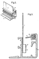
- Figure 1 shows a retractable closure 1 mounted on a wall 3 in front of a building opening 5.
- the closure essentially comprises a flexible sheet 7 which can be a decorative fabric material, a mere functional insect screen, an energy conservation shield or the like.
- One vertical edge of the flexible sheet 7 is attached to a header bar 13 which is guided along the upper and lower guide tracks 9, 11.
- the opposite vertical edge of the flexible sheet 7 is concealed within a vertical box 15 which houses a retractor mechanism, of conventional type such as a spring biased roller.
- the retractor mechanism within box 15 either collects the flexible sheet material upon movement of the header bar 13 to an open position or pays out the sheet material upon movement of the header bar 13 to a closed position of the closure.
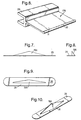
- Figure 2 shows a portion of the bottom guide track 11 and a portion of the flexible sheet 7 guided therein.
- the guide track 11 which is in the form of a guide channel has its upwardly directed opening partially closed off by a flexible guiding strip 17. To reduce friction on the flexible sheet 7 during opening and closing of the structure the flexible strip 17 preferably does not bear against the flexible sheet.
- Figure 3 shows a cross-section of the structure of Figure 2 in which it can be seen that the lower edge of the flexible sheet 7 is provided with a pliable tongue 19.
- the pliable tongue 19 has a free edge 21, also visible in Figure 2, which is deflected and spaced from the flexible sheet 7.
- Figure 3 also shows that the flexible guiding strip 17 is engaged in a channel 23 provided for that purpose in the upper end of the guiding channel. If the flexible sheet 7 is subjected to minor forces such as gusts of wind then the pliable tongue 19 will be securely retained within the guide track 11 by the guiding strip 17. However, if forces are applied to the sheet 7 of a more excessive magnitude then the flexibility of the pliable tongue 19 and the flexible guiding strip 17 will allow the sheet 7 to escape from the guide track 11.
- Figure 4 represents a partial cross-sectional perspective view of a lower guide channel.
- the flexible sheet 7 in this embodiment is represented as an insect screen mesh. At the lower edge of this screen mesh is attached an engagement member in the form of a pliable tongue 19A.
- Attachment of the engagement member to the lower screen edge can be by any suitable means, such as welding, gluing or by an overlying flexible adhesive tape.
- an adhesive strip can be formed on the flexible sheet by a hot-melt adhesive deposition thereon.
- Such hot-melt deposition can be brought into contact with the engagement members while being deposited thereon, or be remelted at a later stage to receive the engagement members.
- the bottom guide track 11 is represented as a short section to allow the interior to be viewed. It should be understood that the guide track will in reality be much longer than the section illustrated in Figure 4. Similarly it should be understood that for simplicity the structure according to the present invention is described with respect to the lower guide track 11, but could be similarly provided on the upper track 9 or on both tracks at the same time.
- the pliable tongue 19A is cutout from a base plate 25, which has a flat shape as illustrated in Figure 5.
- the shape of the engagement member illustrated in Figure 5 can advantageously be obtained by die cutting of a suitable material such as polyester sheet material.
- Hot-melt adhesive can advantageously be used in this manner as it loses its stickiness upon solidification.
- the guiding strip 17A is formed as an integral extrusion having a mounting socket 29 which directly engages in the guide track 11 and a flexible flap portion 31.
- the guiding strip 17A is suitably extruded from polycarbonate plastic.
- One suitable type of adhesive is an acrylate type adhesive which may be applied to a tape 27 as shown in Figure 5.
- the flexible sheet 7 is an insect screen mesh it may be necessary to place an additional tape or foil material on the opposite side of the mesh to prevent the adhesive from seeping through.
- the tape 27 may alternatively be formed in situ on the flexible sheet material as a hot-melt adhesive deposition.
- a substantial voluminous shape of the engagement members may be achieved when the flexible sheet is in a flattened and extended position.
- the pliable tongues lie substantially flush with the surface of the rolled up sheet and do not significantly add to the thickness of the rolled layers.
- plastic material for the pliable tongues and guiding strips may be used.
- the materials mentioned hereinbefore are merely indicative of one suitable embodiment.
Landscapes
- Engineering & Computer Science (AREA)
- Structural Engineering (AREA)
- Life Sciences & Earth Sciences (AREA)
- Insects & Arthropods (AREA)
- Pest Control & Pesticides (AREA)
- Architecture (AREA)
- Civil Engineering (AREA)
- Operating, Guiding And Securing Of Roll- Type Closing Members (AREA)
Claims (11)
- Zurückziehbarer Verschluß für eine Gebäudeöffnung, der genannte Verschluß umfassend eine flexible Bahn (7) mit einander gegenüber angeordneten ersten und zweiten seitlichen Kanten und einer dritten Kante, die sich quer zu den genannten ersten und zweiten seitlichen Kanten erstreckt, einen Rückzugsmechanismus (15), der mit der dritten Kante verbunden ist, wobei die flexible Bahn (7) gegen den Rückzugsmechanismus in eine ausgezogene Position über die genannte Gebäudeöffnung ausgezogen werden kann, während sie vom Rückzugsmechanismus in eine zurückgezogene Position zurückgezogen werden kann, erste und zweite Führungsbahnen (9, 10), die so angeordnet sind, daß sie die erste bzw. zweite seitliche Kante für die Bewegung entlang der Führungsbahnen aufnehmen, und Eingriffsglieder (19), die an mindestens einer der genannten ersten und zweiten Kanten befestigt sind, um die genannte mindestens eine seitliche Kante im Eingriff mit der entsprechenden einen der genannten ersten und zweiten Führungsbahnen zu halten, dadurch gekennzeichnet, d a ß die genannten Eingriffsglieder biegsame Zungen (19, 19A) umfassen, die so vorgespannt sind, daß sie in der ausgezogenen Position der flexiblen Bahn von der flexiblen Bahn weg weisen und in der zurückgezogenen Position der flexiblen Bahn im wesentlichen in einer Ebene mit der flexiblen Bahn angeordnet sind.
- Verschluß nach Anspruch 1, dadurch gekennzeichnet, daß die genannte flexible Bahn (7) aus einem Abschirmungsmaterial besteht.
- Verschluß nach Anspruch 1 oder 2, dadurch gekennzeichnet, daß an beiden der genannten ersten und zweiten seitlichen Kanten Eingriffsglieder in Form der genannten biegsamen Zungen (19, 19A) befestigt sind.
- Verschluß nach Anspruch 1, 2 oder 3, dadurch gekennzeichnet, daß das oder jedes Eingriffsglied einen Basisteil (25) und einen flexiblen Zungen-Befestigungsteil (35) umfaßt, der mit dem genannten Basisteil verbunden ist.
- Verschluß nach Anspruch 4, dadurch gekennzeichnet, daß nur der genannte Basisteil (25) an der genannten flexiblen Bahn (7) befestigt ist.
- Verschluß nach einem der vorstehenden Ansprüche, dadurch gekennzeichnet, daß der genannte Verschluß so gestaltet ist, daß er in einer horizontalen Richtung zurückgezogen werden kann.
- Verschluß nach einem der vorstehenden Ansprüche, dadurch gekennzeichnet, daß das genannte Rückzugsglied (15) eine federgespannte Trommel ist.
- Verschluß nach einem der vorstehenden Ansprüche, dadurch gekennzeichnet, daß jede Führungsbahn (9, 11) die Form eines Kanals hat.
- Verschluß nach Anspruch 8, dadurch gekennzeichnet, daß der genannte Kanal teilweise mit einem flexiblen Führungsstreifen (17) verschlossen ist.
- Verschluß nach einem der vorstehenden Ansprüche, dadurch gekennzeichnet, daß das/die genannte(n) Eingriffsglied(er) mit Schmelzkleber an der genannten Bahn (7) festgeklebt ist/sind.
- Verschluß nach Anspruch 10, dadurch gekennzeichnet, daß der Schmelzkleber auf der Bahn so aufgebracht wird, daß er ein durchgehendes Band bildet, welches die Kanten der Bahn versteift.
Priority Applications (1)
| Application Number | Priority Date | Filing Date | Title |
|---|---|---|---|
| EP19970102522 EP0790384B1 (de) | 1996-02-19 | 1997-02-17 | Einziehbarer Verschluss |
Applications Claiming Priority (3)
| Application Number | Priority Date | Filing Date | Title |
|---|---|---|---|
| EP96200477 | 1996-02-19 | ||
| EP96200477 | 1996-02-19 | ||
| EP19970102522 EP0790384B1 (de) | 1996-02-19 | 1997-02-17 | Einziehbarer Verschluss |
Publications (2)
| Publication Number | Publication Date |
|---|---|
| EP0790384A1 EP0790384A1 (de) | 1997-08-20 |
| EP0790384B1 true EP0790384B1 (de) | 2002-05-02 |
Family
ID=26142538
Family Applications (1)
| Application Number | Title | Priority Date | Filing Date |
|---|---|---|---|
| EP19970102522 Expired - Lifetime EP0790384B1 (de) | 1996-02-19 | 1997-02-17 | Einziehbarer Verschluss |
Country Status (1)
| Country | Link |
|---|---|
| EP (1) | EP0790384B1 (de) |
Cited By (1)
| Publication number | Priority date | Publication date | Assignee | Title |
|---|---|---|---|---|
| US9624722B2 (en) | 2013-02-28 | 2017-04-18 | Odl, Incorporated | Retractable flexible-panel door |
Families Citing this family (7)
| Publication number | Priority date | Publication date | Assignee | Title |
|---|---|---|---|---|
| US6478070B2 (en) * | 1999-12-06 | 2002-11-12 | John Poppema | Retractable flexible door method and apparatus |
| WO2006133556A1 (en) * | 2005-06-16 | 2006-12-21 | Screenline Innovations Inc. | Retractable screen door housing handle balancing system |
| NL2003830C2 (nl) | 2009-11-19 | 2011-05-23 | Unilux Nederland B V | Insektenhor. |
| DE102013018390A1 (de) * | 2013-11-02 | 2015-05-07 | Gardinia Home Decor Gmbh | Rollo mit Profilstab |
| ITUA20163337A1 (it) * | 2016-05-11 | 2017-11-11 | Mv Line S P A | Dispositivo di guida e di tensionamento a scomparsa per schermature a scorrimento |
| EP3848552B1 (de) * | 2020-01-10 | 2023-06-07 | REMIS Gesellschaft für Entwicklung und Vertrieb von technischen Elementen mbH | System zur führung eines flexiblen vorhangs |
| IT202300010047A1 (it) * | 2023-05-18 | 2024-11-18 | Dfm S R L | Dispositivo di schermatura per ambienti |
Family Cites Families (5)
| Publication number | Priority date | Publication date | Assignee | Title |
|---|---|---|---|---|
| US3149665A (en) * | 1962-01-19 | 1964-09-22 | Hunter Douglas Int Quebec Ltd | Roller type screens for windows |
| NL8200456A (nl) * | 1982-02-05 | 1983-09-01 | Cornelis Maria Van Wesenbeeck | Rolhordeur. |
| FR2602539B1 (fr) * | 1986-08-11 | 1989-06-09 | Hayashiguchi Seizo | Ecran de fenetre |
| GB2211540A (en) * | 1987-08-27 | 1989-07-05 | Hunter Douglas Ind Bv | Latch for blind |
| GB2249809A (en) * | 1990-11-15 | 1992-05-20 | Hunter Douglas Ind Bv | A retractable, flexible closure for a door or window opening |
-
1997
- 1997-02-17 EP EP19970102522 patent/EP0790384B1/de not_active Expired - Lifetime
Cited By (3)
| Publication number | Priority date | Publication date | Assignee | Title |
|---|---|---|---|---|
| US9624722B2 (en) | 2013-02-28 | 2017-04-18 | Odl, Incorporated | Retractable flexible-panel door |
| US10047558B2 (en) | 2013-02-28 | 2018-08-14 | Odl, Incorporated | Retractable flexible-panel door |
| US10947779B2 (en) | 2013-02-28 | 2021-03-16 | Larson Manufacturing Company Of South Dakota, Inc. | Method for mounting a flexible-panel door to a door frame of a building |
Also Published As
| Publication number | Publication date |
|---|---|
| EP0790384A1 (de) | 1997-08-20 |
Similar Documents
| Publication | Publication Date | Title |
|---|---|---|
| US6065525A (en) | Rollup door assembly | |
| AU718959B2 (en) | Door sill arrangement in an elevator car | |
| US5515902A (en) | Reinforced shutter panel | |
| US4148953A (en) | Air pervious weatherstrip | |
| US6722416B2 (en) | Flexible curtain rollup door with combination stiffening struts and windlocks | |
| US5819474A (en) | Temporary shelter and method of making same | |
| US4792178A (en) | Truck tonneau cover assembly | |
| EP0790384B1 (de) | Einziehbarer Verschluss | |
| US4993471A (en) | Self-mounting vehicle screen | |
| EP0099454B1 (de) | Sonnenblende, insbesondere für Fahrzeuge | |
| US6186215B1 (en) | Multi-positional rolling window screen | |
| WO2012050518A1 (en) | Window screen device | |
| EP1112875A2 (de) | Sonnendach | |
| KR20010021729A (ko) | 저마찰 에지를 갖는 말아올림형 도어 | |
| EP2404008A1 (de) | Dichtvorrichtung zur fugenabdichtung zwischen zwei bauteilen | |
| US20090115203A1 (en) | Door with retractable screen | |
| US5983570A (en) | Safety device for sliding glass doors | |
| PL209071B1 (pl) | Zestaw drzwiowy | |
| IT8612498A1 (it) | Paraspigolo per portiere di autoveicoli | |
| EP2626483B1 (de) | Putzleiste mit einem sichtbaren Bereich aus transparentem Kunststoff | |
| JPH0513910Y2 (de) | ||
| GB2123069A (en) | Window screen | |
| CA1081113A (en) | Valances | |
| KR102550256B1 (ko) | 차량용 방충망 | |
| EP0659370B1 (de) | Vitrine zur Zurschaustellung von Gegenständen |
Legal Events
| Date | Code | Title | Description |
|---|---|---|---|
| PUAI | Public reference made under article 153(3) epc to a published international application that has entered the european phase |
Free format text: ORIGINAL CODE: 0009012 |
|
| AK | Designated contracting states |
Kind code of ref document: A1 Designated state(s): CH DE FR IT LI NL SE |
|
| 17P | Request for examination filed |
Effective date: 19980209 |
|
| GRAG | Despatch of communication of intention to grant |
Free format text: ORIGINAL CODE: EPIDOS AGRA |
|
| 17Q | First examination report despatched |
Effective date: 20010515 |
|
| GRAG | Despatch of communication of intention to grant |
Free format text: ORIGINAL CODE: EPIDOS AGRA |
|
| GRAH | Despatch of communication of intention to grant a patent |
Free format text: ORIGINAL CODE: EPIDOS IGRA |
|
| GRAH | Despatch of communication of intention to grant a patent |
Free format text: ORIGINAL CODE: EPIDOS IGRA |
|
| GRAA | (expected) grant |
Free format text: ORIGINAL CODE: 0009210 |
|
| AK | Designated contracting states |
Kind code of ref document: B1 Designated state(s): CH DE FR IT LI NL SE |
|
| PG25 | Lapsed in a contracting state [announced via postgrant information from national office to epo] |
Ref country code: LI Free format text: LAPSE BECAUSE OF FAILURE TO SUBMIT A TRANSLATION OF THE DESCRIPTION OR TO PAY THE FEE WITHIN THE PRESCRIBED TIME-LIMIT Effective date: 20020502 Ref country code: IT Free format text: LAPSE BECAUSE OF FAILURE TO SUBMIT A TRANSLATION OF THE DESCRIPTION OR TO PAY THE FEE WITHIN THE PRESCRIBED TIME-LIMIT;WARNING: LAPSES OF ITALIAN PATENTS WITH EFFECTIVE DATE BEFORE 2007 MAY HAVE OCCURRED AT ANY TIME BEFORE 2007. THE CORRECT EFFECTIVE DATE MAY BE DIFFERENT FROM THE ONE RECORDED. Effective date: 20020502 Ref country code: FR Free format text: LAPSE BECAUSE OF FAILURE TO SUBMIT A TRANSLATION OF THE DESCRIPTION OR TO PAY THE FEE WITHIN THE PRESCRIBED TIME-LIMIT Effective date: 20020502 Ref country code: CH Free format text: LAPSE BECAUSE OF FAILURE TO SUBMIT A TRANSLATION OF THE DESCRIPTION OR TO PAY THE FEE WITHIN THE PRESCRIBED TIME-LIMIT Effective date: 20020502 |
|
| REG | Reference to a national code |
Ref country code: CH Ref legal event code: EP |
|
| REF | Corresponds to: |
Ref document number: 69712241 Country of ref document: DE Date of ref document: 20020606 |
|
| PG25 | Lapsed in a contracting state [announced via postgrant information from national office to epo] |
Ref country code: SE Free format text: LAPSE BECAUSE OF FAILURE TO SUBMIT A TRANSLATION OF THE DESCRIPTION OR TO PAY THE FEE WITHIN THE PRESCRIBED TIME-LIMIT Effective date: 20020802 |
|
| PG25 | Lapsed in a contracting state [announced via postgrant information from national office to epo] |
Ref country code: DE Free format text: LAPSE BECAUSE OF FAILURE TO SUBMIT A TRANSLATION OF THE DESCRIPTION OR TO PAY THE FEE WITHIN THE PRESCRIBED TIME-LIMIT Effective date: 20020803 |
|
| REG | Reference to a national code |
Ref country code: CH Ref legal event code: PL |
|
| EN | Fr: translation not filed | ||
| PLBE | No opposition filed within time limit |
Free format text: ORIGINAL CODE: 0009261 |
|
| STAA | Information on the status of an ep patent application or granted ep patent |
Free format text: STATUS: NO OPPOSITION FILED WITHIN TIME LIMIT |
|
| 26N | No opposition filed |
Effective date: 20030204 |
|
| PGFP | Annual fee paid to national office [announced via postgrant information from national office to epo] |
Ref country code: NL Payment date: 20050203 Year of fee payment: 9 |
|
| PG25 | Lapsed in a contracting state [announced via postgrant information from national office to epo] |
Ref country code: NL Free format text: LAPSE BECAUSE OF NON-PAYMENT OF DUE FEES Effective date: 20060901 |
|
| NLV4 | Nl: lapsed or anulled due to non-payment of the annual fee |
Effective date: 20060901 |