EP0789909B1 - Retroreflective marker for data storage cartridge - Google Patents
Retroreflective marker for data storage cartridge Download PDFInfo
- Publication number
- EP0789909B1 EP0789909B1 EP96905193A EP96905193A EP0789909B1 EP 0789909 B1 EP0789909 B1 EP 0789909B1 EP 96905193 A EP96905193 A EP 96905193A EP 96905193 A EP96905193 A EP 96905193A EP 0789909 B1 EP0789909 B1 EP 0789909B1
- Authority
- EP
- European Patent Office
- Prior art keywords
- cartridge
- detector
- marker
- drive
- irradiance
- Prior art date
- Legal status (The legal status is an assumption and is not a legal conclusion. Google has not performed a legal analysis and makes no representation as to the accuracy of the status listed.)
- Expired - Lifetime
Links
- 239000003550 marker Substances 0.000 title claims abstract description 34
- 238000013500 data storage Methods 0.000 title claims abstract description 16
- 239000000463 material Substances 0.000 claims description 26
- 238000001514 detection method Methods 0.000 claims description 9
- 230000000737 periodic effect Effects 0.000 claims description 2
- 230000003287 optical effect Effects 0.000 description 13
- 235000012489 doughnuts Nutrition 0.000 description 5
- NIXOWILDQLNWCW-UHFFFAOYSA-N acrylic acid group Chemical group C(C=C)(=O)O NIXOWILDQLNWCW-UHFFFAOYSA-N 0.000 description 3
- 238000003780 insertion Methods 0.000 description 3
- 230000037431 insertion Effects 0.000 description 3
- 108020003564 Retroelements Proteins 0.000 description 2
- 239000011324 bead Substances 0.000 description 2
- 230000007423 decrease Effects 0.000 description 2
- 239000000428 dust Substances 0.000 description 2
- 239000011521 glass Substances 0.000 description 2
- 238000010521 absorption reaction Methods 0.000 description 1
- 238000003491 array Methods 0.000 description 1
- 230000000903 blocking effect Effects 0.000 description 1
- 239000012612 commercial material Substances 0.000 description 1
- 239000000356 contaminant Substances 0.000 description 1
- 230000023077 detection of light stimulus Effects 0.000 description 1
- 238000002474 experimental method Methods 0.000 description 1
- 238000005286 illumination Methods 0.000 description 1
- 230000013011 mating Effects 0.000 description 1
- 238000000034 method Methods 0.000 description 1
- 230000002093 peripheral effect Effects 0.000 description 1
- 239000002985 plastic film Substances 0.000 description 1
- 238000006748 scratching Methods 0.000 description 1
- 230000002393 scratching effect Effects 0.000 description 1
- 230000035945 sensitivity Effects 0.000 description 1
- 238000004088 simulation Methods 0.000 description 1
- 230000003746 surface roughness Effects 0.000 description 1
Images


Classifications
-
- G—PHYSICS
- G11—INFORMATION STORAGE
- G11B—INFORMATION STORAGE BASED ON RELATIVE MOVEMENT BETWEEN RECORD CARRIER AND TRANSDUCER
- G11B23/00—Record carriers not specific to the method of recording or reproducing; Accessories, e.g. containers, specially adapted for co-operation with the recording or reproducing apparatus ; Intermediate mediums; Apparatus or processes specially adapted for their manufacture
- G11B23/28—Indicating or preventing prior or unauthorised use, e.g. cassettes with sealing or locking means, write-protect devices for discs
- G11B23/283—Security features, e.g. digital codes
- G11B23/285—Security features, e.g. digital codes on the container or cartridge
-
- G—PHYSICS
- G11—INFORMATION STORAGE
- G11B—INFORMATION STORAGE BASED ON RELATIVE MOVEMENT BETWEEN RECORD CARRIER AND TRANSDUCER
- G11B23/00—Record carriers not specific to the method of recording or reproducing; Accessories, e.g. containers, specially adapted for co-operation with the recording or reproducing apparatus ; Intermediate mediums; Apparatus or processes specially adapted for their manufacture
- G11B23/02—Containers; Storing means both adapted to cooperate with the recording or reproducing means
- G11B23/03—Containers for flat record carriers
- G11B23/0301—Details
- G11B23/0302—Auxiliary features
-
- G—PHYSICS
- G11—INFORMATION STORAGE
- G11B—INFORMATION STORAGE BASED ON RELATIVE MOVEMENT BETWEEN RECORD CARRIER AND TRANSDUCER
- G11B23/00—Record carriers not specific to the method of recording or reproducing; Accessories, e.g. containers, specially adapted for co-operation with the recording or reproducing apparatus ; Intermediate mediums; Apparatus or processes specially adapted for their manufacture
- G11B23/02—Containers; Storing means both adapted to cooperate with the recording or reproducing means
- G11B23/03—Containers for flat record carriers
- G11B23/0301—Details
- G11B23/031—Indicating means, e.g. sticker, bar code
-
- G—PHYSICS
- G11—INFORMATION STORAGE
- G11B—INFORMATION STORAGE BASED ON RELATIVE MOVEMENT BETWEEN RECORD CARRIER AND TRANSDUCER
- G11B23/00—Record carriers not specific to the method of recording or reproducing; Accessories, e.g. containers, specially adapted for co-operation with the recording or reproducing apparatus ; Intermediate mediums; Apparatus or processes specially adapted for their manufacture
- G11B23/02—Containers; Storing means both adapted to cooperate with the recording or reproducing means
- G11B23/03—Containers for flat record carriers
- G11B23/0301—Details
- G11B23/0313—Container cases
-
- G—PHYSICS
- G11—INFORMATION STORAGE
- G11B—INFORMATION STORAGE BASED ON RELATIVE MOVEMENT BETWEEN RECORD CARRIER AND TRANSDUCER
- G11B23/00—Record carriers not specific to the method of recording or reproducing; Accessories, e.g. containers, specially adapted for co-operation with the recording or reproducing apparatus ; Intermediate mediums; Apparatus or processes specially adapted for their manufacture
- G11B23/02—Containers; Storing means both adapted to cooperate with the recording or reproducing means
- G11B23/04—Magazines; Cassettes for webs or filaments
- G11B23/041—Details
- G11B23/042—Auxiliary features
-
- G—PHYSICS
- G11—INFORMATION STORAGE
- G11B—INFORMATION STORAGE BASED ON RELATIVE MOVEMENT BETWEEN RECORD CARRIER AND TRANSDUCER
- G11B23/00—Record carriers not specific to the method of recording or reproducing; Accessories, e.g. containers, specially adapted for co-operation with the recording or reproducing apparatus ; Intermediate mediums; Apparatus or processes specially adapted for their manufacture
- G11B23/02—Containers; Storing means both adapted to cooperate with the recording or reproducing means
- G11B23/04—Magazines; Cassettes for webs or filaments
- G11B23/041—Details
- G11B23/046—Indicating means, e.g. quantity of tape
-
- G—PHYSICS
- G11—INFORMATION STORAGE
- G11B—INFORMATION STORAGE BASED ON RELATIVE MOVEMENT BETWEEN RECORD CARRIER AND TRANSDUCER
- G11B23/00—Record carriers not specific to the method of recording or reproducing; Accessories, e.g. containers, specially adapted for co-operation with the recording or reproducing apparatus ; Intermediate mediums; Apparatus or processes specially adapted for their manufacture
- G11B23/30—Record carriers not specific to the method of recording or reproducing; Accessories, e.g. containers, specially adapted for co-operation with the recording or reproducing apparatus ; Intermediate mediums; Apparatus or processes specially adapted for their manufacture with provision for auxiliary signals
Definitions
- the present invention relates to a removable data storage cartridge and to a data storage drive for receiving same. More particularly, the present invention relates to methods and apparatus for detecting the presence of the correct disk cartridge in the data storage drive, and to protecting against the insertion of incompatible or write protected disk cartridges in the drive.
- Removable disk cartridges for storing digital electronic information typically comprise an outer casing or shell that houses a rotatable recording medium, or disk, upon which electronic information can be stored.
- the cartridge shell often comprises upper and lower halves that are joined together to house the disk.
- the disk is mounted on a hub that rotates freely within the cartridge.
- a spindle motor in the drive engages with the disk hub in order to rotate the disk within the cartridge.
- the outer shell of the cartridge typically has some form of opening near its forward edge to provide the recording heads of the drive with access to the recording surfaces of the disk.
- a shutter or door mechanism is often provided to cover the opening when the cartridge is not in use to prevent dust or other contaminants from entering the cartridge and settling on the recording surface of the disk.
- Disk drives for receiving removable disk cartridges must have some mechanism for detecting the insertion or presence of a disk cartridge in the drive.
- the actuator that carries the recording heads of the disk drive across the recording surfaces of the disk should not be allowed to move unless the presence of a disk cartridge is detected.
- mechanical switches are typically employed to detect the presence of a disk cartridge within the drive. Such switches are typically positioned such that when a disk cartridge is inserted fully into the drive, the cartridge contacts the switch, thereby providing an indication that the disk cartridge is present.
- Retroflective materials have been developed. This material has many periodic miniature corner cubes, or spherical elements, which reflect light striking it almost exactly upon its incident path. Retroflective array materials are described in Jacobs, S.F., "Experiments with retrodirective arrays," Optical Engineering , Vol. 21, No. 2, March/April 1982; Rennilson, J., “Retroreflection - What is it and how is it used?" ASTM Standardization News, Feb. 1982; and Venable, W.H., Stephenson, H.F. and Tersteiege, H., "Factor affecting the metrology of retroflective materials," Applied Optics , Vol. 19, No. 8, 15 April 1980.
- EP-A-0 210 629 discloses a cassette with indicating means, for instance a bar code.
- the bar code is indicative of the operating parameters to be used in the drive, so that the operation of the drive may be adapted to different types of recording medium.
- US-A-5 323 243 discloses cassettes with a sticker applied to a side wall, the sticker bearing a bar code pattern comprising a number of black lines on a white background. Based upon the reading of the bar code by a standard bar code reader, the driver accepts or not the cassette, by moving a blocking pawl in or out of the path of the cassette.
- EP-A-0 565 281 discloses a magnetic disk comprising on its outer surface a series of holograms; the information conveyed in the series of holograms is used for allowing access to the information stored on the recording medium of the magnetic disk, by comparizon with information stored on the disk.
- EP-A-0 203 752 discloses a retroreflective transparent sheet containing a directional image. This sheet is used for authentication, e.g. for authentication of cassettes, phonographs or the like.
- US-A-4 762 292 discloses a vacuum column web loop position sensing system, using light emitters and receptors, and a retroreflective material for reflecting light from the emitters to the receptors.
- the vacuum column may be used for material such as magnetic tape.
- US-A-5 038 359 discloses an apparatus using pseudo-conjugator to produce retroreflected seed beam for four wave mixing. This documents uses an flat array of retroreflecting elements in the form of sphere or corner reflectors.
- a retroreflective marker on a data storage cartridge is detected by a light detector.
- the data storage cartridge contains a magnetic or optical recording disk or tape for storing data.
- the detection system is much less range and distance sensitive than other types of reflective material used in conjunction with a light source and light detector.
- an emitter/detector pair with appropriate low cost optics are positioned in a magnetic disk drive. This emitter/detector pair is connected in a cartridge detection system.
- the marker identifies whether the cartridge is write protected.
- the retrodirective tag is a molded acrylic tag.
- Advantages of the present invention include its insensitivity to range and angularity of the marker relative to the emitter/detector in the drive as well as the robust nature of the marker and emitter/detector to scratching and tolerance of moderate optical path dust or debris buildup.
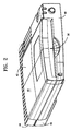
- Figs. 1 - 3 show the cartridge and the disk drive to which the present invention is applicable.
- the cartridge and drive are described in co-pending applications entitled “Disk Cartridge and Data Storage Device For Receiving Same", Serial No. 324,671, filed October 18, 1994 (Attorney Docket No. IOM-8907) and "APPARATUS FOR PERFORMING MULTIPLE FUNCTIONS IN A DATA STORAGE DEVICE USING A SINGLE ELECTRO-MECHANICAL DEVICE", Serial No. 324,808, filed October 18, 1994 (Attorney Docket No. 8906). These disclosures are incorporated herein by reference.
- the disk cartridge 10 comprises an outer casing 12 having upper and lower shells that mate to form the casing.
- a disk-shaped recording medium is affixed to a hub 16 that is rotatably mounted in the casing 12.
- An opening on the bottom shell of the casing 12 provides access to the disk hub 16.
- a head access opening in the front peripheral edge 20 of the disk cartridge 10 provides access to the recording surfaces of the disk by the recording heads of a disk drive.
- a retroretlective marker, or tag, 11 is positioned on the cartridge to be detected by the detector in the disk drive. Further in accordance with the invention. a write protected marker 13 of retroreflective material may be applied to the cartridge if it is "write protected”.
- Fig. 2 shows a data storage device, in this case a disk drive 40, for receiving the disk cartridge 10 of Fig. 1.
- the disk drive 40 comprises an outer housing 42 having top and bottom covers 44, 46 and a front panel 48.
- a disk cartridge can be inserted into the disk drive 40 through a horizontal opening 50 in the front panel 48 of the disk drive 40.
- Fig. 3 is a top view of the disk drive 40 of the present invention with the top cover 44 removed.
- the disk drive 40 comprises an internal platform 50 that slides along opposing side rails 52, 54 between a forward position and a rearward position.
- a pair of springs 56, 58 bias the platform 50 in its foward position.
- a linear actuator is mounted on the rear of the platform 50.
- the linear actuator comprises a carriage assembly 62 having two lightweight flexible arms 64,66.
- the recording heads 18, 19 of the disk drive are mounted at the ends of the respective arms 64,66.
- a coil 68 which is part of a voice coil motor. is mounted at the opposite end of the carriage 62.
- the coil 68 interacts with magnets (not shown) to move the carriage linearly so that the heads 18 and 19 can move radially over respective recording surfaces of a disk cartridge inserted into the disk drive.
- a head locking lever 72 is also pivotally mounted on the platform 50 about a rotation shaft 72b.
- a second spring (not shown) is coupled to head locking lever 72 at its rotation shaft 72b also to bias the head locking lever 72 in the X- direction.
- An end 72a of the head locking lever which extends at a right angle to the main shaft of the lever 72, is adapted to releasably engage an end 62a of the actuator carriage 62 when the carriage 62 is in a fully retracted position, thereby locking the carriage in place and preventing inadvertent movement of the recording heads 18, 19.
- a solenoid 74 has a drive shaft 76.
- the drive shaft 76 moves in the X- direction from a normally extended position toward a retracted position.
- an enlarged operating end 76A of the drive shaft 76 engages the eject latch and head locking levers 70, 72 in order to pull the levers in the X-direction against their normal spring bias.
- Movement of the head locking lever 72 in the X- direction causes the end 72A of the head locking lever 72 to disengage from the end 62A of the carriage 62. thereby unlocking the actuator and allowing the actuator to move radially of the rotating disk.
- movement of the eject latch lever 70 in the X-direction causes the cutout 70A on the eject latch lever to disengage from the latch projection thereby releasing the platform 50 and allowing the platform 50 to move back to its forward position.
- an emitter/detector pair 20 (Fig. 4) is positioned in the drive to detect the retroreflective marker 11 and to unlock the actuator.
- the emitter/detector pair 20 includes an LED light source 21 and a detector 22.
- the emitter/detector pair 20 is positioned on the PC board of the disk drive so that light from the source passes through the slit 23 (Fig. 3) in the base plate, is reflected by marker 11, and travels on its incident path to be detected by detector 22.
- the detector 22 is closely spaced to the LED emitter 21. Therefore, the detector will optimally respond to light which is emitted from the source 21, reflected from the retroreflective material in the marker 11, and is incident upon the emitter/detector pair 20 (E/D pair) along the same wavepath that the light was emitted. Because of the unique characteristics of the retroreflective material in the marker 11, the spacing between the marker 11 and the detector 13 is not critical. The spacing is denoted by the arrow 24. Similarly, the angular tolerance, denoted by the angle 25 is not critical.
- the signal from the detector 22 is applied through suitable electronics 26 to enable actuation of solenoid 74, thereby allowing the drive to access the cartridge.
- a textured lens cover 27 (Fig.4) is provided. Internal curved optical surfaces 31 and 32 (Fig. 5) expand the reflected optical irradiance such that its convergence is transferred to the detector in order that the return detected optical signal is maximized.
- the prism lens 27A is used to redirect light reflected by the retroreflective array material, which would otherwise be directed back at its source, toward the photo-sensor 22. If the appropriate prism lens is not used, the retroreflected light will be reflected back into the source LED 21.
- lens prism which help frustrate the use of other types of reflective materials and also the use of a lens in conjunction with other reflective materials.
- surface roughness or waviness of the top of the lens prism which has a spatial frequency of less than the pitch of the retroreflective elements (0.006") will be corrected by optically using the retroreflective cartridge marker.
- This will frustrate the use of both ordinary mirrors and reflectors used in conjunction with lenses.
- Just putting an angular surface on the front face of the prism lens will frustrate the use of polished mirrors if the angle is made large enough.
- the corrective polished mirror that would be required is of such a large tilt angle that it would be difficult, if not impossible, to locate on a cartridge.
- a retroreflective write protection marker 13 may be provided on the cartridge. The presence of this marker is detected in a manner similar to the detection of the marker 11.
- An emitter detector pair 28 (Fig. 4) detects marker 13 through slit 29 (Fig. 3) in the base plate. The detector output is applied through suitable electronics 26a to the write protect circuitry 30. This is used for write protection on the cartridge.
- Fig. 5 shows an embodiment of the invention in which a beam splitter 31 redirects the reflected light to the detector 22. This embodiment is useful where the source 21 is not in the same package as the detector 22.
- Appropriate optical baffling can be used and optical element surface angularity can be used to reduce emitter back scatter to the detector which is a source of cartridge detection noise.
- Retrodirective or optical phase conjugate-type materials are included within the definition of retroreflective as used herein.
- One commercial material suitable for use is available from Reflexite Corporation, under their designation "AP 1000" or Reflexite. This is a thin plastic sheet material with tiny (0.006" pitch) retroreflective elements embossed into it. This embodiment requires a “lens prism” such that the reflected light will be redirected into the detector (phototransistor).
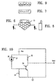
- an acrylic retroreflective marker, or tag 13A shown in Figs. 7-9 is used.
- This tag is an array of retroreflective corner cubes whose pitch and flat-to-flat distance is slightly greater than the distance between the emitter/detector (E/D) pair used to sense the tag.
- the pitch on the tag's corner cubes is 94 mils while the LED is spaced 70 mils from the phototransistor in the E/D pair.
- the E/D pair senses a fairly reflective object at 0.7 mm.
- the distance in the drive from the pair to the cartridge is about 13 mm.
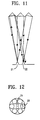
- each corner-cube element (9 in tag of the preferred embodiment) reflects the diffuse incident light back at the LED with an illuminance profile that is annular. If a retroreflector has a size (diameter) which is slightly greater than 70 mils, i.e., 94 mils, the returned light distribution from each retroreflective element will have a donut shaped distribution around the center of the emitter. The donut's radius will about 94 mils. As can be seen from Figs. 11 and 12, a segment, or lobe, of this donut illuminates the detector 22. There are six peak lobes in the irradiance distribution of Fig. 12. This is from the hexagonal shape of each element in the tag 13A. (See Fig. 6).
- the OD radius of the donut is approximately the diameter, or flat-to-flat, distance 34 of the corner cubes, i.e., 94 mils.
- the phototransistor at 70 mils from the center of the LED views a segment of this reflected annular irradiance. Reflection off a polished mirror or white piece of paper at this distance is so diffuse and angle insensitive that the irradiance return to the phototransistor aperture is small by comparison.
- the return donut of light would be 2" in diameter. From this example. it can also be seen that in order to maximize the return to the detector using this retroreflection scheme, it is important to only oversize the retro element's diameter slightly larger that the spacing between the source of irradiance and sensing elements (emitter/detector).
- the differences in the return of light from the two retroreflective materials, Reflexite and a molded acrylic tag, are basically in the diameter of the returned spot of illumination.
- the retroreflected spot is about 12 mils. in diameter and requires the "lens prism" to redirect light to the detector for sensing.
- a suitable emitter/detector is commercially available, for example, from Sharp Corporation and designated Model No. GP 2S27. It is the E/D pair 31 in the circuit of Fig. 10. Resistor 32 is 10K and has a tolerance of +/-5%. The 2N3904 transistor 34 has a +/-50% tolerance on its Beta, the E/D pair 31 has a 2:1 range for phototransistor output current given a particular reflective target. The optical elements in the tag marker 13 have a variance range of about 20% in their reflective efficiency.
- resistor 33 in the circuit was selected to be 50K ohms to give adequate sensitivity to the tag while also providing significant rejection to diffuse or specular reflective tag substitutes.
- Tests show that there is close to an order of magnitude difference in the output signal from E/D pair 31 for a typical (avg.) retroreflective tag and typical (avg.) E/D pair versus the output seen from a mirror or white piece of paper by a hot E/D pair.
- the tests also show that there is about a 2 to 2.5 times margin between the signal seen from a specular or diffuse tag substitute and the cartridge detection threshold.
- the preferred embodiment also includes some margin for low end E/D pairs with low end tags which are scratched or otherwise optically degraded through use. The detector still functions with these low end conditions.
Landscapes
- Engineering & Computer Science (AREA)
- Computer Security & Cryptography (AREA)
- Optical Recording Or Reproduction (AREA)
- Illuminated Signs And Luminous Advertising (AREA)
- Packaging Of Annular Or Rod-Shaped Articles, Wearing Apparel, Cassettes, Or The Like (AREA)
- Optical Record Carriers And Manufacture Thereof (AREA)
Applications Claiming Priority (3)
| Application Number | Priority Date | Filing Date | Title |
|---|---|---|---|
| US08/388,242 US5638228A (en) | 1995-02-14 | 1995-02-14 | Retroreflective marker for data storage cartridge |
| US388242 | 1995-02-14 | ||
| PCT/US1996/000885 WO1996025737A1 (en) | 1995-02-14 | 1996-01-29 | Retroreflective marker for data storage cartridge |
Publications (3)
| Publication Number | Publication Date |
|---|---|
| EP0789909A1 EP0789909A1 (en) | 1997-08-20 |
| EP0789909A4 EP0789909A4 (enExample) | 1997-09-24 |
| EP0789909B1 true EP0789909B1 (en) | 2001-04-11 |
Family
ID=23533271
Family Applications (1)
| Application Number | Title | Priority Date | Filing Date |
|---|---|---|---|
| EP96905193A Expired - Lifetime EP0789909B1 (en) | 1995-02-14 | 1996-01-29 | Retroreflective marker for data storage cartridge |
Country Status (7)
| Country | Link |
|---|---|
| US (1) | US5638228A (enExample) |
| EP (1) | EP0789909B1 (enExample) |
| JP (1) | JPH11500560A (enExample) |
| AT (1) | ATE200592T1 (enExample) |
| CA (1) | CA2212848A1 (enExample) |
| DE (2) | DE789909T1 (enExample) |
| WO (1) | WO1996025737A1 (enExample) |
Families Citing this family (62)
| Publication number | Priority date | Publication date | Assignee | Title |
|---|---|---|---|---|
| US5986838A (en) * | 1995-02-14 | 1999-11-16 | Iomega Corporation | Thin retroreflective marker for data storage cartridge |
| US6067214A (en) * | 1995-02-14 | 2000-05-23 | Iomega Corporation | Data cartridge marker for foreign object detection |
| US6097562A (en) * | 1995-02-14 | 2000-08-01 | Iomega Corporation | Disk drive for detecting a retroreflective marker on a data storage cartridge |
| US5940255A (en) * | 1996-05-14 | 1999-08-17 | Mitsumi Electric Co., Ltd. | Large-capacity flexible disk and high-density type disk drive used therefor |
| US6181662B1 (en) | 1997-09-26 | 2001-01-30 | Iomega Corporation | Latent irradiance discrimination method and marker system for cartridgeless data storage disks |
| US6359745B1 (en) | 1997-09-26 | 2002-03-19 | Iomega Corporation | Latent illuminance discrimination marker system for data storage cartridges |
| US6201662B1 (en) * | 1998-09-25 | 2001-03-13 | Iomega Corporation | Latent illuminance discrimination marker with reflective layer for data storage cartridges |
| US6091563A (en) * | 1997-09-26 | 2000-07-18 | Iomega Corporation | Latent illuminance discrimination marker system for data storage cartridges |
| US6264107B1 (en) | 1997-09-26 | 2001-07-24 | Iomega Corporation | Latent illuminance discrimination marker system for authenticating articles |
| US5992011A (en) * | 1997-10-29 | 1999-11-30 | Iomega Corporation | Method of assembling a baffle to a detector for detecting a retroreflective marker |
| US7123444B1 (en) | 1998-05-22 | 2006-10-17 | Tanberg Data Asa | Tape cassette having an optical signal receiver and a memory for storing information optically transmitted into the cassette |
| US6259575B1 (en) | 1998-07-01 | 2001-07-10 | Iomega Corporation | Readable indelible mark on storage media |
| US6297924B1 (en) | 1998-11-13 | 2001-10-02 | Iomega Corporation | System and method for cartridge detection and verification using signal comparison |
| US6297923B1 (en) | 1998-11-13 | 2001-10-02 | Iomega Corporation | Disk-cartridge detection system incorporating an angled light emitter/detector |
| US6459544B1 (en) | 1998-11-20 | 2002-10-01 | Bruce M. Harper | Removable cartridge for data-storage medium |
| US6587297B1 (en) | 2000-02-18 | 2003-07-01 | Robin Reinhard Padden | System and method for detecting the presence of a data-storage cartridge using phase-rotated polarized light |
| US6424492B1 (en) * | 2000-04-24 | 2002-07-23 | Iomega Corporation | Frequency based cartridge detection system |
| EP1227489A1 (en) | 2000-11-01 | 2002-07-31 | SAMSUNG ELECTRONICS Co. Ltd. | Disk cartridge and disk drive apparatus |
| US6763521B2 (en) | 2001-01-15 | 2004-07-13 | Iomega Corporation | Low cost storage device and method of using the same |
| US6693858B2 (en) * | 2001-03-21 | 2004-02-17 | Hewlett-Packard Development Company, L.P. | Data cartridge detector |
| KR100754159B1 (ko) * | 2001-04-12 | 2007-09-03 | 삼성전자주식회사 | 디스크 수납용 어댑터 및 디스크 드라이브 장치 |
| JP2003051174A (ja) * | 2001-05-15 | 2003-02-21 | Fuji Photo Film Co Ltd | カートリッジ、及び、ドライブ装置 |
| TWI285885B (en) * | 2001-10-17 | 2007-08-21 | Samsung Electronics Co Ltd | Disk cartridge and disk drive apparatus |
| US7161579B2 (en) | 2002-07-18 | 2007-01-09 | Sony Computer Entertainment Inc. | Hand-held computer interactive device |
| US7102615B2 (en) * | 2002-07-27 | 2006-09-05 | Sony Computer Entertainment Inc. | Man-machine interface using a deformable device |
| US8797260B2 (en) | 2002-07-27 | 2014-08-05 | Sony Computer Entertainment Inc. | Inertially trackable hand-held controller |
| US7883415B2 (en) | 2003-09-15 | 2011-02-08 | Sony Computer Entertainment Inc. | Method and apparatus for adjusting a view of a scene being displayed according to tracked head motion |
| US7623115B2 (en) | 2002-07-27 | 2009-11-24 | Sony Computer Entertainment Inc. | Method and apparatus for light input device |
| US7646372B2 (en) * | 2003-09-15 | 2010-01-12 | Sony Computer Entertainment Inc. | Methods and systems for enabling direction detection when interfacing with a computer program |
| US7760248B2 (en) | 2002-07-27 | 2010-07-20 | Sony Computer Entertainment Inc. | Selective sound source listening in conjunction with computer interactive processing |
| US8313380B2 (en) | 2002-07-27 | 2012-11-20 | Sony Computer Entertainment America Llc | Scheme for translating movements of a hand-held controller into inputs for a system |
| US7391409B2 (en) * | 2002-07-27 | 2008-06-24 | Sony Computer Entertainment America Inc. | Method and system for applying gearing effects to multi-channel mixed input |
| US9474968B2 (en) | 2002-07-27 | 2016-10-25 | Sony Interactive Entertainment America Llc | Method and system for applying gearing effects to visual tracking |
| US8570378B2 (en) | 2002-07-27 | 2013-10-29 | Sony Computer Entertainment Inc. | Method and apparatus for tracking three-dimensional movements of an object using a depth sensing camera |
| US9393487B2 (en) | 2002-07-27 | 2016-07-19 | Sony Interactive Entertainment Inc. | Method for mapping movements of a hand-held controller to game commands |
| US7627139B2 (en) * | 2002-07-27 | 2009-12-01 | Sony Computer Entertainment Inc. | Computer image and audio processing of intensity and input devices for interfacing with a computer program |
| US8686939B2 (en) * | 2002-07-27 | 2014-04-01 | Sony Computer Entertainment Inc. | System, method, and apparatus for three-dimensional input control |
| US9682319B2 (en) | 2002-07-31 | 2017-06-20 | Sony Interactive Entertainment Inc. | Combiner method for altering game gearing |
| US20040099740A1 (en) * | 2002-11-25 | 2004-05-27 | Chresand Thomas J. | Merchandising components for authenticating products, and combinations and methods utilizing the same |
| US9177387B2 (en) | 2003-02-11 | 2015-11-03 | Sony Computer Entertainment Inc. | Method and apparatus for real time motion capture |
| US8072470B2 (en) * | 2003-05-29 | 2011-12-06 | Sony Computer Entertainment Inc. | System and method for providing a real-time three-dimensional interactive environment |
| US10279254B2 (en) | 2005-10-26 | 2019-05-07 | Sony Interactive Entertainment Inc. | Controller having visually trackable object for interfacing with a gaming system |
| US7874917B2 (en) | 2003-09-15 | 2011-01-25 | Sony Computer Entertainment Inc. | Methods and systems for enabling depth and direction detection when interfacing with a computer program |
| US9573056B2 (en) | 2005-10-26 | 2017-02-21 | Sony Interactive Entertainment Inc. | Expandable control device via hardware attachment |
| US8287373B2 (en) | 2008-12-05 | 2012-10-16 | Sony Computer Entertainment Inc. | Control device for communicating visual information |
| US8323106B2 (en) | 2008-05-30 | 2012-12-04 | Sony Computer Entertainment America Llc | Determination of controller three-dimensional location using image analysis and ultrasonic communication |
| US7663689B2 (en) * | 2004-01-16 | 2010-02-16 | Sony Computer Entertainment Inc. | Method and apparatus for optimizing capture device settings through depth information |
| US7686692B2 (en) * | 2004-05-10 | 2010-03-30 | Sony Computer Entertainment Inc. | Pattern codes used for interactive control of computer applications and video game applications |
| US8547401B2 (en) | 2004-08-19 | 2013-10-01 | Sony Computer Entertainment Inc. | Portable augmented reality device and method |
| US8781151B2 (en) | 2006-09-28 | 2014-07-15 | Sony Computer Entertainment Inc. | Object detection using video input combined with tilt angle information |
| US8310656B2 (en) | 2006-09-28 | 2012-11-13 | Sony Computer Entertainment America Llc | Mapping movements of a hand-held controller to the two-dimensional image plane of a display screen |
| USRE48417E1 (en) | 2006-09-28 | 2021-02-02 | Sony Interactive Entertainment Inc. | Object direction using video input combined with tilt angle information |
| US8542907B2 (en) | 2007-12-17 | 2013-09-24 | Sony Computer Entertainment America Llc | Dynamic three-dimensional object mapping for user-defined control device |
| EP2367033A1 (en) * | 2008-01-14 | 2011-09-21 | Avery Dennison Corporation | Retroreflector for use in touch screen applications and positions sensing system |
| US8840470B2 (en) | 2008-02-27 | 2014-09-23 | Sony Computer Entertainment America Llc | Methods for capturing depth data of a scene and applying computer actions |
| US8368753B2 (en) | 2008-03-17 | 2013-02-05 | Sony Computer Entertainment America Llc | Controller with an integrated depth camera |
| US8961313B2 (en) * | 2009-05-29 | 2015-02-24 | Sony Computer Entertainment America Llc | Multi-positional three-dimensional controller |
| US8527657B2 (en) | 2009-03-20 | 2013-09-03 | Sony Computer Entertainment America Llc | Methods and systems for dynamically adjusting update rates in multi-player network gaming |
| US8342963B2 (en) | 2009-04-10 | 2013-01-01 | Sony Computer Entertainment America Inc. | Methods and systems for enabling control of artificial intelligence game characters |
| US8142288B2 (en) | 2009-05-08 | 2012-03-27 | Sony Computer Entertainment America Llc | Base station movement detection and compensation |
| US8393964B2 (en) | 2009-05-08 | 2013-03-12 | Sony Computer Entertainment America Llc | Base station for position location |
| USD766251S1 (en) * | 2012-04-11 | 2016-09-13 | Sony Corporation | Disc cartridge |
Family Cites Families (15)
| Publication number | Priority date | Publication date | Assignee | Title |
|---|---|---|---|---|
| US3718078A (en) * | 1970-12-31 | 1973-02-27 | Polaroid Corp | Smoothly granulated optical surface and method for making same |
| DE2135059A1 (de) * | 1971-07-14 | 1973-01-25 | Ulo Werk M Ullmann | Aufklebbares rueckstrahlelement |
| JPS5897167A (ja) * | 1981-12-04 | 1983-06-09 | Hitachi Ltd | デイスクカ−トリツジ |
| US4633451A (en) * | 1982-06-30 | 1986-12-30 | International Business Machines Corporation | Optical servo for magnetic disks |
| JPS5936092U (ja) * | 1982-08-30 | 1984-03-06 | 富士写真フイルム株式会社 | 磁気デイスクカ−トリツジ |
| US4688894A (en) * | 1985-05-13 | 1987-08-25 | Minnesota Mining And Manufacturing Company | Transparent retroreflective sheets containing directional images and method for forming the same |
| KR870001564A (ko) * | 1985-07-29 | 1987-03-14 | 와타리 스기이찌로 | 정보기억매체 및 그 정보처리장치 |
| US4762292A (en) * | 1987-01-30 | 1988-08-09 | Anci Alexander M D | Vacuum column web loop position sensing system |
| NL8802763A (nl) * | 1988-11-10 | 1990-06-01 | Philips Nv | Systeem voor het registreren en/of uitlezen van signalen op informatiedragers in cassettes. |
| US5038359A (en) * | 1989-10-10 | 1991-08-06 | Hughes Aircraft Company | Self-pumped, optical phase conjugation method and apparatus using pseudo-conjugator to produce retroreflected seed beam |
| JPH0461650A (ja) * | 1990-06-27 | 1992-02-27 | Matsushita Electric Ind Co Ltd | テープカセットの誤消去防止装置 |
| JPH04167286A (ja) * | 1990-10-31 | 1992-06-15 | Canon Inc | カセット |
| JPH05289612A (ja) * | 1992-04-06 | 1993-11-05 | Nhk Spring Co Ltd | 情報記録システム及び情報通信システム |
| JPH06168540A (ja) * | 1992-11-30 | 1994-06-14 | Matsushita Electric Ind Co Ltd | 記憶装置 |
| WO1995003558A1 (en) * | 1993-07-19 | 1995-02-02 | Reflexite Corporation | Retroreflective structure |
-
1995
- 1995-02-14 US US08/388,242 patent/US5638228A/en not_active Expired - Fee Related
-
1996
- 1996-01-29 EP EP96905193A patent/EP0789909B1/en not_active Expired - Lifetime
- 1996-01-29 JP JP8524953A patent/JPH11500560A/ja active Pending
- 1996-01-29 AT AT96905193T patent/ATE200592T1/de not_active IP Right Cessation
- 1996-01-29 DE DE0789909T patent/DE789909T1/de active Pending
- 1996-01-29 CA CA002212848A patent/CA2212848A1/en not_active Abandoned
- 1996-01-29 WO PCT/US1996/000885 patent/WO1996025737A1/en not_active Ceased
- 1996-01-29 DE DE69612473T patent/DE69612473T2/de not_active Expired - Fee Related
Also Published As
| Publication number | Publication date |
|---|---|
| JPH11500560A (ja) | 1999-01-12 |
| CA2212848A1 (en) | 1996-08-22 |
| DE69612473D1 (de) | 2001-05-17 |
| DE69612473T2 (de) | 2002-04-18 |
| EP0789909A4 (enExample) | 1997-09-24 |
| EP0789909A1 (en) | 1997-08-20 |
| DE789909T1 (de) | 1998-02-19 |
| ATE200592T1 (de) | 2001-04-15 |
| WO1996025737A1 (en) | 1996-08-22 |
| US5638228A (en) | 1997-06-10 |
Similar Documents
| Publication | Publication Date | Title |
|---|---|---|
| EP0789909B1 (en) | Retroreflective marker for data storage cartridge | |
| US6292319B1 (en) | Thin retroreflective marker for identifying an object | |
| US3966330A (en) | Phonograph record detecting arrangement | |
| KR0175291B1 (ko) | 신호 기록 및 판독 시스테 | |
| EP0391588B1 (en) | Disc cartridge | |
| US6067214A (en) | Data cartridge marker for foreign object detection | |
| JPH08249854A (ja) | 書き込み保護機構付きトレイおよびそれを収納するカートリッジ | |
| US4819114A (en) | Write-protected data storage disk assembly | |
| US6097562A (en) | Disk drive for detecting a retroreflective marker on a data storage cartridge | |
| US7032233B2 (en) | Cartridge housing a recording medium and drive device for recording medium | |
| US6067207A (en) | Recording and/or reproducing apparatus including a slider with an inclined guide at a front end portion thereof | |
| US6297923B1 (en) | Disk-cartridge detection system incorporating an angled light emitter/detector | |
| US6297924B1 (en) | System and method for cartridge detection and verification using signal comparison | |
| US6693858B2 (en) | Data cartridge detector | |
| NL8304191A (nl) | Cassette voor een magnetische registratieschijf. | |
| US5992011A (en) | Method of assembling a baffle to a detector for detecting a retroreflective marker | |
| US5808997A (en) | Disk drive apparatus capable of reliably receiving disk cartridges having both single and double sided disks | |
| US6587297B1 (en) | System and method for detecting the presence of a data-storage cartridge using phase-rotated polarized light | |
| US5769347A (en) | Tape cartridge | |
| JP3503327B2 (ja) | テープカートリッジ | |
| JPH0828098B2 (ja) | 記録媒体を収納したカ−トリツジ | |
| WO1999053495A1 (en) | Tape cartridge | |
| JPH0467345A (ja) | ディスクカートリッジ装着装置 | |
| JPH0547155A (ja) | デイスクカートリツジ | |
| JPH07122032A (ja) | データカートリッジ及びデータカートリッジの仕様識別装置 |
Legal Events
| Date | Code | Title | Description |
|---|---|---|---|
| PUAI | Public reference made under article 153(3) epc to a published international application that has entered the european phase |
Free format text: ORIGINAL CODE: 0009012 |
|
| 17P | Request for examination filed |
Effective date: 19970314 |
|
| AK | Designated contracting states |
Kind code of ref document: A1 Designated state(s): AT BE CH DE DK ES FR GB GR IE IT LI LU MC NL PT SE |
|
| RHK1 | Main classification (correction) |
Ipc: G11B 23/03 |
|
| A4 | Supplementary search report drawn up and despatched |
Effective date: 19970807 |
|
| AK | Designated contracting states |
Kind code of ref document: A4 Designated state(s): AT BE CH DE DK ES FR GB GR IE IT LI LU MC NL PT SE |
|
| ITCL | It: translation for ep claims filed |
Representative=s name: STUDIO TORTA SOCIETA' SEMPLICE |
|
| 17Q | First examination report despatched |
Effective date: 19971103 |
|
| DET | De: translation of patent claims | ||
| GRAG | Despatch of communication of intention to grant |
Free format text: ORIGINAL CODE: EPIDOS AGRA |
|
| GRAG | Despatch of communication of intention to grant |
Free format text: ORIGINAL CODE: EPIDOS AGRA |
|
| GRAH | Despatch of communication of intention to grant a patent |
Free format text: ORIGINAL CODE: EPIDOS IGRA |
|
| GRAH | Despatch of communication of intention to grant a patent |
Free format text: ORIGINAL CODE: EPIDOS IGRA |
|
| GRAA | (expected) grant |
Free format text: ORIGINAL CODE: 0009210 |
|
| AK | Designated contracting states |
Kind code of ref document: B1 Designated state(s): AT BE CH DE DK ES FR GB GR IE IT LI LU MC NL PT SE |
|
| PG25 | Lapsed in a contracting state [announced via postgrant information from national office to epo] |
Ref country code: LI Free format text: LAPSE BECAUSE OF FAILURE TO SUBMIT A TRANSLATION OF THE DESCRIPTION OR TO PAY THE FEE WITHIN THE PRESCRIBED TIME-LIMIT Effective date: 20010411 Ref country code: CH Free format text: LAPSE BECAUSE OF FAILURE TO SUBMIT A TRANSLATION OF THE DESCRIPTION OR TO PAY THE FEE WITHIN THE PRESCRIBED TIME-LIMIT Effective date: 20010411 Ref country code: BE Free format text: LAPSE BECAUSE OF FAILURE TO SUBMIT A TRANSLATION OF THE DESCRIPTION OR TO PAY THE FEE WITHIN THE PRESCRIBED TIME-LIMIT Effective date: 20010411 Ref country code: AT Free format text: LAPSE BECAUSE OF FAILURE TO SUBMIT A TRANSLATION OF THE DESCRIPTION OR TO PAY THE FEE WITHIN THE PRESCRIBED TIME-LIMIT Effective date: 20010411 |
|
| REF | Corresponds to: |
Ref document number: 200592 Country of ref document: AT Date of ref document: 20010415 Kind code of ref document: T |
|
| REG | Reference to a national code |
Ref country code: CH Ref legal event code: EP |
|
| REG | Reference to a national code |
Ref country code: IE Ref legal event code: FG4D |
|
| REF | Corresponds to: |
Ref document number: 69612473 Country of ref document: DE Date of ref document: 20010517 |
|
| ET | Fr: translation filed | ||
| ITF | It: translation for a ep patent filed | ||
| PG25 | Lapsed in a contracting state [announced via postgrant information from national office to epo] |
Ref country code: PT Free format text: LAPSE BECAUSE OF FAILURE TO SUBMIT A TRANSLATION OF THE DESCRIPTION OR TO PAY THE FEE WITHIN THE PRESCRIBED TIME-LIMIT Effective date: 20010711 Ref country code: DK Free format text: LAPSE BECAUSE OF FAILURE TO SUBMIT A TRANSLATION OF THE DESCRIPTION OR TO PAY THE FEE WITHIN THE PRESCRIBED TIME-LIMIT Effective date: 20010711 |
|
| PG25 | Lapsed in a contracting state [announced via postgrant information from national office to epo] |
Ref country code: GR Free format text: LAPSE BECAUSE OF FAILURE TO SUBMIT A TRANSLATION OF THE DESCRIPTION OR TO PAY THE FEE WITHIN THE PRESCRIBED TIME-LIMIT Effective date: 20010713 |
|
| REG | Reference to a national code |
Ref country code: CH Ref legal event code: PL |
|
| PG25 | Lapsed in a contracting state [announced via postgrant information from national office to epo] |
Ref country code: ES Free format text: LAPSE BECAUSE OF FAILURE TO SUBMIT A TRANSLATION OF THE DESCRIPTION OR TO PAY THE FEE WITHIN THE PRESCRIBED TIME-LIMIT Effective date: 20011030 |
|
| REG | Reference to a national code |
Ref country code: GB Ref legal event code: IF02 |
|
| PG25 | Lapsed in a contracting state [announced via postgrant information from national office to epo] |
Ref country code: LU Free format text: LAPSE BECAUSE OF NON-PAYMENT OF DUE FEES Effective date: 20020129 Ref country code: IE Free format text: LAPSE BECAUSE OF NON-PAYMENT OF DUE FEES Effective date: 20020129 |
|
| PG25 | Lapsed in a contracting state [announced via postgrant information from national office to epo] |
Ref country code: SE Free format text: LAPSE BECAUSE OF NON-PAYMENT OF DUE FEES Effective date: 20020130 |
|
| PLBE | No opposition filed within time limit |
Free format text: ORIGINAL CODE: 0009261 |
|
| STAA | Information on the status of an ep patent application or granted ep patent |
Free format text: STATUS: NO OPPOSITION FILED WITHIN TIME LIMIT |
|
| 26N | No opposition filed | ||
| PG25 | Lapsed in a contracting state [announced via postgrant information from national office to epo] |
Ref country code: NL Free format text: LAPSE BECAUSE OF NON-PAYMENT OF DUE FEES Effective date: 20020801 Ref country code: MC Free format text: LAPSE BECAUSE OF NON-PAYMENT OF DUE FEES Effective date: 20020801 |
|
| EUG | Se: european patent has lapsed |
Ref document number: 96905193.7 |
|
| NLV4 | Nl: lapsed or anulled due to non-payment of the annual fee |
Effective date: 20020801 |
|
| REG | Reference to a national code |
Ref country code: IE Ref legal event code: MM4A |
|
| PGFP | Annual fee paid to national office [announced via postgrant information from national office to epo] |
Ref country code: GB Payment date: 20040121 Year of fee payment: 9 |
|
| PGFP | Annual fee paid to national office [announced via postgrant information from national office to epo] |
Ref country code: FR Payment date: 20040122 Year of fee payment: 9 |
|
| PGFP | Annual fee paid to national office [announced via postgrant information from national office to epo] |
Ref country code: DE Payment date: 20040301 Year of fee payment: 9 |
|
| PG25 | Lapsed in a contracting state [announced via postgrant information from national office to epo] |
Ref country code: IT Free format text: LAPSE BECAUSE OF NON-PAYMENT OF DUE FEES Effective date: 20050129 Ref country code: GB Free format text: LAPSE BECAUSE OF NON-PAYMENT OF DUE FEES Effective date: 20050129 |
|
| PG25 | Lapsed in a contracting state [announced via postgrant information from national office to epo] |
Ref country code: DE Free format text: LAPSE BECAUSE OF NON-PAYMENT OF DUE FEES Effective date: 20050802 |
|
| GBPC | Gb: european patent ceased through non-payment of renewal fee |
Effective date: 20050129 |
|
| PG25 | Lapsed in a contracting state [announced via postgrant information from national office to epo] |
Ref country code: FR Free format text: LAPSE BECAUSE OF NON-PAYMENT OF DUE FEES Effective date: 20050930 |
|
| REG | Reference to a national code |
Ref country code: FR Ref legal event code: ST |