EP0789232A2 - Procédé pour le calibrage d'une balance - Google Patents
Procédé pour le calibrage d'une balance Download PDFInfo
- Publication number
- EP0789232A2 EP0789232A2 EP97101995A EP97101995A EP0789232A2 EP 0789232 A2 EP0789232 A2 EP 0789232A2 EP 97101995 A EP97101995 A EP 97101995A EP 97101995 A EP97101995 A EP 97101995A EP 0789232 A2 EP0789232 A2 EP 0789232A2
- Authority
- EP
- European Patent Office
- Prior art keywords
- calibration
- load
- calibration device
- parallel
- link
- Prior art date
- Legal status (The legal status is an assumption and is not a legal conclusion. Google has not performed a legal analysis and makes no representation as to the accuracy of the status listed.)
- Granted
Links
- 238000005303 weighing Methods 0.000 title claims description 7
- 238000000034 method Methods 0.000 title description 3
- 230000007246 mechanism Effects 0.000 claims abstract description 38
- 238000005452 bending Methods 0.000 claims description 61
- 230000008878 coupling Effects 0.000 claims description 55
- 238000010168 coupling process Methods 0.000 claims description 55
- 238000005859 coupling reaction Methods 0.000 claims description 55
- 238000005520 cutting process Methods 0.000 claims description 20
- 230000005540 biological transmission Effects 0.000 claims description 9
- 230000000295 complement effect Effects 0.000 claims description 9
- 230000005484 gravity Effects 0.000 claims description 8
- 230000000284 resting effect Effects 0.000 claims description 4
- 239000000463 material Substances 0.000 description 30
- 230000009467 reduction Effects 0.000 description 8
- 230000003628 erosive effect Effects 0.000 description 3
- 241000047428 Halter Species 0.000 description 2
- 238000010276 construction Methods 0.000 description 2
- 238000013461 design Methods 0.000 description 2
- 238000009760 electrical discharge machining Methods 0.000 description 2
- 238000005259 measurement Methods 0.000 description 2
- 230000008569 process Effects 0.000 description 2
- 229910000838 Al alloy Inorganic materials 0.000 description 1
- 229910000851 Alloy steel Inorganic materials 0.000 description 1
- 230000015572 biosynthetic process Effects 0.000 description 1
- 239000002131 composite material Substances 0.000 description 1
- 238000012423 maintenance Methods 0.000 description 1
- 238000004519 manufacturing process Methods 0.000 description 1
- 238000004321 preservation Methods 0.000 description 1
- 230000035945 sensitivity Effects 0.000 description 1
- 239000000725 suspension Substances 0.000 description 1
- 238000013519 translation Methods 0.000 description 1
- XLYOFNOQVPJJNP-UHFFFAOYSA-N water Substances O XLYOFNOQVPJJNP-UHFFFAOYSA-N 0.000 description 1
Images


Classifications
-
- G—PHYSICS
- G01—MEASURING; TESTING
- G01G—WEIGHING
- G01G23/00—Auxiliary devices for weighing apparatus
- G01G23/01—Testing or calibrating of weighing apparatus
- G01G23/012—Testing or calibrating of weighing apparatus with load cells comprising in-build calibration weights
Definitions
- the invention relates to a calibration device for a balance having a load-bearing device for loads to be weighed, a load-measuring device and a lever mechanism serving to transmit power between the load-bearing device and the load-measuring device, which is coupled to the load-bearing device with an input-side coupling area and to the load-measuring device with an output-side coupling area , wherein the lever mechanism further comprises a coupling area separated from the input-side and the output-side coupling area for releasably coupling a calibration force that can be decoupled for normal weighing operation.
- an approximately V-shaped receptacle for a calibration weight is provided in a lever which serves to reduce the force between the load receiving device and the load measuring device.
- a calibration weight that is decoupled from the lever inside the scale during normal weighing operation can be inserted into the holder.
- the receptacle is arranged on the lever in such a way that the weight of the calibration weight with its full amount, ie. H. without reduction, acts on the load measuring device.
- the calibration weight To use the absolute accuracy of a balance that can be achieved due to the resolution, which can be 0.1 g or even higher when using a 32 kg load cell, for example, when using the known calibration device, the calibration weight must be in the longitudinal direction of the lever as well as perpendicular to it with a positional accuracy of the order of 10 -3 mm on the longitudinal axis of the lever in the receptacle. An extremely complex mechanism for releasably coupling the calibration weight is required to ensure such positional accuracy. If the calibration weight is connected less accurately, the absolute accuracy of the balance determined by the resolution cannot be achieved.
- the invention has for its object to provide a calibration device of the type mentioned, which is mechanically simple with high calibration accuracy.
- the coupling area serving for calibration has a parallelogram guide element which is guided parallel to the direction of the calibration force and serves to releasably couple it with two mutually parallel links, which are connected at one end by the parallel link and at their other ends by a fixed link.
- the parallelogram guidance used to couple the calibration force greatly reduces the sensitivity to torque when the calibration force is introduced. A significant reduction in the dependency of the force transmitted from the coupling area serving for releasable coupling to the load measuring device on the position of the point of application of the calibration force is achieved.
- the absolute measurement accuracy can be of the order of magnitude of a displayed resolution accuracy 0.1 g can already be achieved with a positional accuracy of the calibration weight in a horizontal plane of the order of 10 -1 mm.
- Such a low positional accuracy can already be achieved with a comparatively simple arrangement for releasably coupling the calibration force to the parallel-guided member of the parallelogram guide.
- the calibration force in the calibration device according to the invention can be coupled particularly easily with a link to the parallel-guided link Calibration weight are generated.
- a particularly compact design of the calibration device according to the invention can be achieved if a carrier device with receiving areas for the calibration weight which extend essentially transversely to the parallelogram plane of the parallelogram guide is arranged on the parallel-guided link. With this arrangement, the calibration weight next to the handlebars, i. H. in a plane running parallel to the parallelogram plane. As a result, an increase in the length of the calibration device, which is generally predetermined by the longitudinal extension of the links and the measuring cell, can be minimized by coupling the calibration weight.
- the carrier device is advantageously provided with a locking element for the calibration weight.
- the locking element can be formed particularly simply in the form of a recess and / or a projection if a complementary projection and / or a complementary recess which can be brought into engagement with it is provided in the calibration weight.
- a well-defined positioning of the calibration weight in the longitudinal direction of the handlebars can be achieved particularly easily if the support device has two, preferably rod-shaped support elements spaced apart from one another in the longitudinal direction of the handlebars and extending essentially parallel to one another.
- Such a carrier element arrangement ensures automatic calibration weight positioning in the longitudinal direction of the handlebars if the calibration weight can be at least partially inserted into the space between the carrier elements and, when coupled, is in contact with both carrier parts with a surface element that runs transversely to a plane defined by the carrier elements.
- the calibration weight can be formed, for example, in the form of a circular cylinder with a diameter that exceeds the distance between the two carrier parts.
- the locking element can be designed particularly simply in the form of at least one web running coaxially to the longitudinal axis of at least one of the support elements, which preferably has the shape of a triangle with an axially adjacent leg on the rod, if the calibration weight is one of the axially sectional shape of the Has ring corresponding recess.
- the recess is preferably formed in the form of a circumferential groove provided in the cylinder surface, preferably in the form of a triangle with a circumferential groove pointing towards the cylinder axis.
- a holder serving to cool the calibration weight in a position detached from the parallel-guided link and for coupling the calibration weight to the parallel-guided link in a second position can be used.
- the holder expediently has a support area on which the calibration weight can be supported against the direction of gravity.
- the support area of the holder advantageously has a calibration weight in the first position transverse to the direction of gravity supporting area, for example in the form of a complementary to a projection of the calibration weight groove.
- the holder can preferably be placed on the calibration weight above and / or below the support elements and in between.
- the holder can expediently be pivoted or displaced in the direction of gravity for adjustment between its first and its second position about an axis which preferably extends perpendicular to the parallelogram plane.
- a particularly reliable securing of the calibration weight in the first position can be achieved if the holder is essentially U-shaped and the calibration weight is held in the first position between the U-legs.
- a particularly compact design can be achieved if the holder is essentially L-shaped, with one of the L-legs resting in the first position on the underside of the calibration weight.
- the region of the parallel-guided link extending between the links is separated from the links at least in sections by a material-free space in the form of a thin cutting line.
- each of the links in a known manner, has two bending points spaced apart in its longitudinal direction, which are opposite the bending points of the other link, at least one of which its side facing the opposite bending point is delimited by a material-free space, on the other hand, delimiting the parallel-guided link in the form of a section of a thin cutting line that curves convexly to this bending point.
- the area of the parallel-guided link which is arranged between the bending point delimited by the material-free space in the form of a thin cutting line and the bending point opposite this can be formed with a particularly large material thickness.
- the high bending stiffness of this area achieved in this way can advantageously be used for the trouble-free introduction of the weight force of a calibration weight resting on a carrier device arranged in this area.
- the area serving to couple the calibration force is on the one hand is articulated via a bending point to the lever mechanism and, on the other hand, via a further bending point to the parallel link.
- the transmission ratio of the force transmission between the input-side coupling area and the output-side coupling area differs from the transmission ratio of the force transmission between the area serving to couple the calibration force and the output-side coupling area.
- the entire weighing range of a 32 kg load cell with a reduction ratio of 1: 100 can be achieved using a calibration weight of only 320 g if the calibration weight acts on the load measuring device with its full weight.
- the load-bearing device also has a load parallelogram guide with two parallel load links, which are connected at one end by a parallel load introduction member and at their other ends by a fixed stand.
- a further reduction in the space requirement of such a device is achieved if the stand simultaneously forms the fixed link of the parallelogram guide of the calibration device, it being particularly advantageous if the parallelogram guide of the calibration device is arranged essentially between the load links.
- An increase in the bending stiffness of the handlebars of the parallelogram guide and / or of individual elements of the lever mechanism can be achieved if at least one handlebar of the parallelogram guide of the calibration device is separated from the stand and / or lever mechanism by a material-free space which at least in sections has the shape of a thin cutting line.
- the bending stiffness of the individual elements of the lever mechanism and the load-bearing device can be increased if the lever mechanism is separated from the load-bearing device by a material-free area, at least in sections, which has the shape of a thin cutting line.
- the calibration device according to the invention can be produced particularly simply, for example, by the process of spark erosion using an erosion wire if the load-bearing device, the lever mechanism and the parallelogram guide are formed in one piece.
- production using a water and / or laser beam is also contemplated.
- the load cell shown in FIG. 1 has a load receiver 12, 14, 16, 18, a lever mechanism comprising three levers, namely a first lever 36, a second lever 38 and a third lever 40, and a calibration device 68 according to the invention.
- These elements are formed in one piece from an essentially cuboid material block 10.
- material blocks are in the material block Spaces in the form of thin cut lines formed by the process of spark erosion using an erosion wire.
- a hole 11 is formed in the material block 10 for threading the erosion wire.
- a rod (not shown) can also be inserted into this hole 11 to block the parallelogram guide of the calibration device according to the invention to be explained later during assembly.
- Aluminum alloys, for example are suitable materials for the one-piece block of material 10. In addition, however, numerous other materials are conceivable, for example steel alloys or composite materials.
- the load carrying device of the load cell shown in FIG. 1 comprises a load parallelogram guide consisting of a fixed stand 12, an upper load link 14, a lower load link 16 and a parallel load introduction member 18.
- the upper load link 14 is separated by a material-free area 20 in the form of a thin cutting line from an area of the stand 12 extending between the upper load link 14 and the lower load link 16.
- the lower load link 16 is separated from the first lever 36 of the lever mechanism to be explained later by a material-free area in the form of a thin section line 26.
- the load introduction member 18 is delimited on its side facing away from the stator 12 by a side surface of the material block 10, while on its side facing the stator 12 it is delimited by material-free areas 22 and 24 in the form of thin cutting lines from the stator 12 or from a first coupling 46 .
- the load links 14 and 16 are connected at one end by the stator 12 and at the other ends by the load introduction member 18.
- the upper load link 14 is articulated on the one hand via a bending point 28 on the stand 12 and on the other hand via a bending point 30 on the load introduction member 18.
- the lower load link 16 is on the one hand via a bending point 34 the stand 12 and on the other hand articulated via a bending point 32 on the load introduction member 18.
- the bending points 28 to 34 are delimited on their sides facing the interior of the material block 10 by sections in the form of outwardly pointing convex curvatures of the material-free spaces 20 and 26. On the outer surfaces of the material block 10, the bending points 28 to 34 are delimited by the convexly curved sections of the material-free regions 20 and 26 of the material blocks 10, which are opposed by convex curvatures.
- the lever mechanism comprising the first lever 36, the second lever 38 and the third lever 40 for reducing a force acting in the direction of the arrow 25 on the load introduction member is arranged between the upper load link 14 and the lower load link 16.
- the first lever 36 which is supported on a bend 42 and is suspended on the stand 12, is on the one hand the bend 42 via a bend 44, the first coupling 46 and a bending point 48 with the load introduction member 18 and on the other hand the bending point 42 via a bending point 50, a second coupling 52 and a bending point 54 is connected to the second lever 38.
- the distance between the bending point 42 serving for hanging support of the first lever and the bending point 44 serving for articulating the first lever 36 to the first coupling 46 is smaller in the load cell shown in FIG. 1 than the distance between the bending point 42 and the articulation point of the first lever 36 to the second coupling 52 serving bending point 50, so that the first lever 36 reduces the force acting on the load introduction member 18.
- the first coupling 46 is provided with recesses 47 extending from the main planes of the material block 10 in the course of its longitudinal extension between the bending points 48 and 44. This reduces the material thickness of the first coupling 46 perpendicular to these main planes. As a result of the flexibility of the first coupling 46 achieved in this way in the direction perpendicular to the parallelogram plane of the load parallelogram guide Possible slight tilting of the load introduction member 18 as a result of the eccentric introduction of the force to be measured is therefore picked up by the first coupling 46 and is not transmitted to the first lever 36.
- the force transmitted by means of the first lever 36 from the load introduction member 18 to the second lever 38 supported on a stand 56 at a bend 56 is transmitted from the second lever 38 via a bend 58, a third coupling 60 and a bend 62 to the one at a bend 64 transferred to the stand 12 supported third lever 40.
- the distance between the bending point 56 serving to support the second lever 38 on the stand 12 and the bending point 56 serving to link the second lever 38 to the first lever 36, on the one hand, the bending point 56 is less than the distance between the bending point 56 and the point for the articulation of the second lever 38 on the bending lever 58 serving the third lever 40 on the other hand, the bending point 56. Therefore, the second lever 38 further reduces the force acting on the load introduction member 18 and transmitted to the second lever 38 via the first lever 36.
- the third lever 40 is provided with recesses 66 on its side opposite the bending point 62 used to link the third lever 40 to the second lever 38, beyond the bending point 64 used to support the third lever 40 on the stand 12.
- These recesses serve as fastening holes for a cantilever (not shown) which projects beyond the material block 10 and which, for example, can carry a coil interacting with a permanent magnet of a magnetic force compensation device serving as a load measuring device.
- a load measuring device in the form of a string that can be excited to vibrate or a strain gauge cell.
- the distance between the hanging support of the third lever 40 on the stand 12 serving bending point 64 and the bending point 62 serving to link the third lever 40 to the third coupling 60 or the second lever 38, on the one hand the bending point 64 is smaller than the distance between the recesses 66 or arranged on the arm defined in the recesses 66 Coil of the bending point 64 on the other hand. Therefore, with the third lever 40, a further reduction of the force acting on the load introduction member 18 and transmitted to the third lever 40 via the first and second levers 36 and 38 is achieved.
- the previously explained elements of the load cell shown in FIG. 1 are formed in one piece and separated from one another by material-free areas in the form of thin cutting lines. This ensures a minimization of the material removal required to form these elements and consequently a maximization of the strength of the individual elements. By maximizing the material thickness, especially in the vicinity of the bending points, maximum strength and resilience are achieved with a minimal construction volume.
- All of the bending points explained so far which serve to articulate the coupling and for the hanging support of the levers, are formed by mutually opposing and complementary arcuate sections of the material-free areas in the form of the thin cutting lines.
- the bending points 42, 44 and 50, the bending points 54, 56 and 58 and the bending points 62 and 64 are each arranged in a horizontal plane. Another arrangement is particularly conceivable for the bending points 42, 44 and 50.
- This parallelogram guide 68 has a fixed member 70 formed by part of the stand 12, an upper link 72, a lower link 74 and a parallel link 76.
- the links 72 and 74 are connected at one end via the fixed link 70 and at their other ends via the parallel link 76.
- the parallel-guided link 76 is connected to a section of the second lever 38 adjacent to the third coupling 60 via a bending point 78, a fourth coupling 80 and a bending point 82 for coupling a force acting thereon. Accordingly, a force acting on the parallel-guided member 76, when it is transmitted to the load measuring device, has a lower reduction than a force acting on the load-introducing member 18.
- the upper link 72 of the parallelogram guide 68 is delimited on its upper side by a material-free area 84, which on the other hand delimits the third lever 40 and the stand 12, in the form of a thin cutting line.
- the upper link 72 of the parallelogram guide 68 is delimited by a material-free region 86 which, on the other hand, delimits a part of the parallel-guided link which extends between the links 72 and 74 and also has the shape of a thin cutting line.
- the lower link 74 is delimited on its upper side by a material-free area 88, which on the other hand delimits the underside of the part of the parallel-guided link 76 which extends between the links 72 and 74 and again has the shape of a thin cutting line, while on the other hand it delimits the area 88 on its underside second lever 38 delimiting material-free area 90 is limited.
- the fourth coupling 80 is separated on the one hand from the parallel link 76 and on the other hand from the end region of the second lever 38 facing the third coupling 60.
- the material-free region 86 which limits the link 72 downward has two convex bulges 93 and 95 spaced apart from one another in the longitudinal direction of the parallelogram guide 68 and facing the material-free region 84.
- the material-free area 88 delimiting the upper side of the link 74 for forming bending points 96 and 98 is provided with convex bulges 97 and 99, which are spaced apart from one another in the longitudinal direction of the parallelogram guide 68 and point towards the material-free area 90.
- the parallel link 76 has a particularly large material thickness and therefore also a particularly high strength. Therefore, recesses 100 and 102 are formed in this area of the parallel-guided link 76, which serve as a receptacle for a carrier device for a calibration weight that extends transversely to the parallelogram plane of the parallelogram guide 68.
- the parallelogram guide 68 largely ensures that the force transmitted from the parallel link 76 to the second lever 38 via the fourth coupling 80 serving as a coupling area for the calibration force is independent of the position of the calibration weight acting on the parallel link.
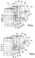
- a mechanism used for releasably coupling the calibration weight to the parallel link 76 can therefore be formed in a particularly simple manner without impairing the calibration accuracy. Exemplary embodiments of such mechanisms are shown in FIGS. 2 and 3.
- the mechanism essentially comprises an approximately U-shaped holder 110 which can be pivoted between a first position shown in FIG. 2a and a second position shown in FIG. 2b.
- the first position shown in FIG. 2a becomes the calibration weight 120 between a base 112 running approximately perpendicular to the main plane of the material block 10 outgoing legs 114 and 116 of the holder 110, which run approximately parallel to the main plane of the material block 10, are held in a position lifted off from the parallel link 76 and thus from the lever mechanism formed by the levers 36, 38 and 40.
- the disk-shaped, essentially circular-cylindrical calibration weight 120 is provided with a shaft running approximately along the cylinder axis, the free ends 124 and 126 of which in the position of the holder 110 shown in FIG. 2a in recesses 115 and 117 in the legs 114 and 116, respectively are included.
- the free ends 124 and 126 in cooperation with the recesses 115 and 117, form a lock for the calibration weight 120 in the position lifted from the load cell.
- the holder 110 To couple the calibration weight 120 to the lever mechanism via the parallel link 76, the holder 110 is pivoted into the position shown in FIG. 2b. In this position, the holder 110 is completely detached from the calibration weight 120.
- the calibration weight now lies on the carrier device of the parallel-guided link 76 which is formed in the form of two rods 104 and 106, respectively, which are received in the recesses 100 and 102 of the parallel-guided link 76.
- the rods 104 and 106 extend approximately perpendicular to the main plane of the material block 10.
- the calibration weight 120 coupled to the lever mechanism is therefore arranged approximately parallel to the parallelogram plane of the parallelogram guide next to the material block 10.
- the elements used to calibrate the scale do not significantly increase the length and height dimensions of the load cell.
- the calibration weight 120 In its position coupled to the lever mechanism, there is a lower region of the calibration weight between the rods 104 and 106, which has a diameter that exceeds the distance between the two rods 104 and 106, the calibration weight 120 on the rods 104 with surface areas having downward-facing surface normals and 106 is present. As a result, the calibration weight 120 is precisely positioned in the longitudinal direction of the links 72 and 74.
- bars 105 and 107 are provided on the rods 104 and 106, which are axially sectionally complementary to a circumferential groove 122 in the circumferential surface of the circular-cylindrical calibration weight 120.
- the webs 105 and 107 are formed axially in the form of a triangle with one leg against the rods 104 and 106, respectively.
- the distance between the webs 105 and 107 and the main surface of the material block 10 facing these webs and the extension of the calibration weight 120 in the longitudinal direction of the rods 104 and 106 are advantageously chosen so that in the position shown in FIG. 2b, the calibration weight 120 is touched and the holder 110 with a cantilever (not shown) which is fixed in the recesses 66 of the third lever 40 and extends to the boundary surface of the stand 12 opposite the load introduction member 19.
- the holder 110 shown in FIG. 2 locks the calibration weight 120 in its position released from the lever mechanism parallel to the main surface of the material block 10 by means of the free ends 124 and 126 of the shaft or the recesses 115 and 117 and vertically to the main surface of the material block 10 by means of the legs 114 and 116.
- this locking requires a comparatively large holder 110.
- a holder 130 which is more compact in comparison is shown in FIG. 3. This approximately L-shaped holder 130 is from a first position shown in FIG. 3a, for holding the calibration weight 120 in a position serving for the position of the parallel guide member 76 and thus lifted from the lever mechanism, into a position shown in FIG.
- the calibration weight 120 for coupling the calibration weight 120 the parallel-guided link 76 and thus the second position serving the lever mechanism can be displaced in the direction of gravity, as indicated by arrow 136.
- the calibration weight 120 in the position shown in FIG. 3b is coupled and locked in a manner similar to that in the embodiment explained with reference to FIG. 2 by means of rods 104 and 106 having webs 105 and 107, cooperating with the one formed in a lateral surface of the calibration weight 120 , groove 122 complementary to the shape of the rings 105 and 107.
- a leg 134 of the holder 130 that extends approximately perpendicular to the main surface of the material block 10 serves as a support for the calibration weight 120 lifted off the rods 104 and 106 a step 135 serving as a stop for the calibration weight 120 is formed.
- the leg 132 of the holder 130 which extends approximately in the direction of gravity, also prevents the calibration weight 120 from completely tilting about an axis running approximately parallel to the links 72 and 74.
- a counter-holder is formed on the housing enclosing the load cell and the parts serving for calibration, to which the calibration weight 120 in its housing in FIGS. 2a and 3a shown lifted position held in plant and is held immovable.
- the entire arrangement is preferably formed symmetrically to the main plane of the material block 10, ie that also on the side of the material block facing away from the viewer in FIGS. 2 and 3 110 an arrangement of the calibration weight 120, rods 104 and 106 and a holder 110 and 130 corresponding to the side facing the viewer is provided.
- the invention is not limited to the exemplary embodiments explained with reference to the drawing.
- the calibration device according to the invention can also be used in an advantageous manner in conjunction with lever mechanisms which provide a force transmission.
- the possibility of connecting two or more calibration weights independently is also contemplated.
Landscapes
- Physics & Mathematics (AREA)
- General Physics & Mathematics (AREA)
- Measurement Of Force In General (AREA)
- Automobile Manufacture Line, Endless Track Vehicle, Trailer (AREA)
- Testing Of Balance (AREA)
- Maintenance And Inspection Apparatuses For Elevators (AREA)
Applications Claiming Priority (4)
| Application Number | Priority Date | Filing Date | Title |
|---|---|---|---|
| DE19605087A DE19605087C2 (de) | 1996-02-12 | 1996-02-12 | Kalibriervorrichtung für eine Waage |
| DE19605087 | 1996-02-12 | ||
| DE29614601U | 1996-08-22 | ||
| DE29614601U DE29614601U1 (de) | 1996-02-12 | 1996-08-22 | Kalibriervorrichtung für eine Waage |
Publications (3)
| Publication Number | Publication Date |
|---|---|
| EP0789232A2 true EP0789232A2 (fr) | 1997-08-13 |
| EP0789232A3 EP0789232A3 (fr) | 1998-06-24 |
| EP0789232B1 EP0789232B1 (fr) | 2002-04-17 |
Family
ID=26022827
Family Applications (1)
| Application Number | Title | Priority Date | Filing Date |
|---|---|---|---|
| EP97101995A Expired - Lifetime EP0789232B1 (fr) | 1996-02-12 | 1997-02-07 | Dispositif de calibrage pour une balance |
Country Status (3)
| Country | Link |
|---|---|
| US (1) | US5866854A (fr) |
| EP (1) | EP0789232B1 (fr) |
| JP (1) | JP3422902B2 (fr) |
Cited By (5)
| Publication number | Priority date | Publication date | Assignee | Title |
|---|---|---|---|---|
| EP1873504A1 (fr) * | 2006-06-28 | 2008-01-02 | Mettler-Toledo AG | Couplage mécanique pour une masse d'étalonnage dans une balance électronique |
| CN111386447A (zh) * | 2017-12-24 | 2020-07-07 | 磅秤 (2008)有限公司 | 平面负载传感器组件 |
| US11933661B2 (en) | 2018-06-28 | 2024-03-19 | Shekel Scales (2008) Ltd. | Systems and methods for weighing products on a shelf |
| US11946795B2 (en) | 2018-05-16 | 2024-04-02 | Shekel Scales (2008) Ltd. | Weighing load cells and arrangements employing them in shelves |
| US11971293B2 (en) | 2018-06-06 | 2024-04-30 | Shekel Scales (2008) Ltd. | Systems and methods for weighing products on a shelf |
Families Citing this family (28)
| Publication number | Priority date | Publication date | Assignee | Title |
|---|---|---|---|---|
| DE19820637A1 (de) * | 1998-05-08 | 1999-11-11 | Mettler Toledo Gmbh | Waage mit einem Ankopplungsbereich für ein Kalibriergewicht |
| DE19845023A1 (de) * | 1998-09-30 | 2000-04-06 | Mettler Toledo Gmbh | Kraftmeßvorrichtung, insbesondere Wägezelle |
| US6414252B1 (en) * | 1998-11-16 | 2002-07-02 | Mettler-Toledo Gmbh | Calibration system for a weighing scale |
| DE19859992B4 (de) * | 1998-12-23 | 2013-12-12 | Mettler-Toledo Ag | Kraftmeßvorrichtung, insbesondere Wägezelle I |
| DE19923207C1 (de) | 1999-05-20 | 2000-10-12 | Sartorius Gmbh | Wägeaufnehmer |
| DE19943439A1 (de) * | 1999-09-11 | 2001-03-15 | Mettler Toledo Gmbh | Vorrichtung zur Kraftuntersetzung in einer Kraftmeßvorrichtung |
| DE10054847C2 (de) * | 2000-11-04 | 2002-10-17 | Sartorius Gmbh | Wägeaufnehmer mit Justiergewicht |
| DE10148762A1 (de) * | 2001-10-02 | 2003-04-24 | Mettler Toledo Gmbh | Dünnstellen-Biegelager für eine Kraftmesseinrichtung und Vorrichtung zur Kraftübertragung mit einem solchen |
| DE50311013D1 (de) | 2003-11-06 | 2009-02-12 | Mettler Toledo Ag | Kraftmesszelle mit Befestigungsentkopplung durch vorstehende Flächen und kurze Einschnitte |
| DE20318788U1 (de) * | 2003-12-01 | 2004-04-01 | Wipotec Wiege- Und Positioniersysteme Gmbh | Kalibriereinrichtung |
| US7091428B2 (en) * | 2004-06-24 | 2006-08-15 | Shinko Denshi Co., Ltd. | Weighing apparatus with Roberval mechanism |
| JP4407451B2 (ja) * | 2004-09-28 | 2010-02-03 | 株式会社島津製作所 | 電子天びん |
| DE502004003701D1 (de) * | 2004-09-30 | 2007-06-14 | Mettler Toledo Ag | Kraftübertragungsvorrichtung für eine Waage |
| DE502004006067D1 (de) * | 2004-12-23 | 2008-03-13 | Mettler Toledo Gmbh | Kalibriergewichtsanordnung für eine elektronische Waage |
| DE502004005293D1 (de) * | 2004-12-23 | 2007-11-29 | Mettler Toledo Ag | Kalibriergewichtsanordnung für eine elektronische Waage |
| ATE418721T1 (de) * | 2005-01-26 | 2009-01-15 | Mettler Toledo Ag | Gravimetrisches messgerät mit kalibriergewicht |
| DE102005043820B4 (de) * | 2005-09-13 | 2007-08-23 | Wipotec Wiege- Und Positioniersysteme Gmbh | Hebelgetriebe, insbesondere für einen Wägeaufnehmer einer nach dem Prinzip der elektromagnetischen Kraftkompensation arbeitenden Waage |
| JP4942390B2 (ja) * | 2006-05-02 | 2012-05-30 | 株式会社エー・アンド・デイ | 電子天秤の荷重計測機構 |
| US8044308B2 (en) * | 2006-08-29 | 2011-10-25 | Shimadzu Corporation | Electronic balance including linking member connected between fulcrum and electromagnetic force generating apparatus |
| JP5243532B2 (ja) * | 2007-06-01 | 2013-07-24 | メトラー−トレド アクチェンゲゼルシャフト | 特に重量測定機器用の調整可能な平行案内機構 |
| DE102008064169B4 (de) * | 2008-12-22 | 2013-07-18 | Hottinger Baldwin Messtechnik Gmbh | Wägezelle |
| DE102010014152B4 (de) | 2010-04-07 | 2015-12-24 | Hottinger Baldwin Messtechnik Gmbh | Wägezelle |
| PL2434264T3 (pl) * | 2010-09-24 | 2014-08-29 | Mettler Toledo Gmbh | Urządzenie przenoszące siłę ze sprzęgalnym odważnikiem kalibracyjnym |
| US9027380B2 (en) | 2012-03-06 | 2015-05-12 | Mettler-Toledo Ag | Force-transmitting mechanism with a calibration weight that can be coupled and uncoupled |
| PL236727B1 (pl) * | 2017-09-15 | 2021-02-08 | Lewandowski Witold Radwag Wagi Elektroniczne | Waga z monolitycznym układem wagowym z przedłużeniem dźwigni dla odważnika kalibracyjnego |
| DE102019130625A1 (de) * | 2019-11-13 | 2021-05-20 | Minebea Intec Aachen GmbH & Co. KG | Wägeaufnehmer mit einer Justiergewichtsschaltung |
| CN113124984B (zh) * | 2019-12-31 | 2026-02-10 | 梅特勒-托利多仪器(上海)有限公司 | 称重传感器及其内校结构 |
| CN115683289B (zh) * | 2021-07-29 | 2024-12-03 | 梅特勒-托利多(常州)精密仪器有限公司 | 集成式高精度称重模块 |
Citations (2)
| Publication number | Priority date | Publication date | Assignee | Title |
|---|---|---|---|---|
| DE2609560A1 (de) | 1976-03-08 | 1977-09-15 | Mettler Instrumente Ag | Waage |
| DE4119734A1 (de) | 1991-06-14 | 1992-12-17 | Mettler Toledo Ag | Vorrichtung zur kraftuntersetzung in einer kraftmesseinrichtung, insbesondere einer waage |
Family Cites Families (8)
| Publication number | Priority date | Publication date | Assignee | Title |
|---|---|---|---|---|
| US4065962A (en) * | 1974-10-29 | 1978-01-03 | Gse, Inc. | Load cell |
| US4338825A (en) * | 1980-10-15 | 1982-07-13 | Eaton Corporation | Strain gage load cell |
| DE3147470A1 (de) * | 1981-12-01 | 1983-07-14 | Bizerba-Werke Wilhelm Kraut GmbH & Co KG, 7460 Balingen | Kraftmessvorrichtung |
| CH661121A5 (en) * | 1983-05-27 | 1987-06-30 | Mettler Instrumente Ag | Electromechanical balance with a lever mechanism and with a connectable calibrating weight |
| DE3639521C2 (de) * | 1986-11-20 | 1994-03-17 | Sartorius Gmbh | Elektrische Waage |
| US4799561A (en) * | 1987-05-09 | 1989-01-24 | Shimadzu Corporation | Electronic balance |
| JP2697106B2 (ja) | 1989-03-31 | 1998-01-14 | 株式会社島津製作所 | 電子天びん |
| DE4305426A1 (de) * | 1993-02-22 | 1994-08-25 | Mettler Toledo Ag | Kraftmeßvorrichtung, insbesondere Waage |
-
1997
- 1997-01-29 US US08/790,928 patent/US5866854A/en not_active Expired - Lifetime
- 1997-02-04 JP JP03426397A patent/JP3422902B2/ja not_active Expired - Lifetime
- 1997-02-07 EP EP97101995A patent/EP0789232B1/fr not_active Expired - Lifetime
Patent Citations (2)
| Publication number | Priority date | Publication date | Assignee | Title |
|---|---|---|---|---|
| DE2609560A1 (de) | 1976-03-08 | 1977-09-15 | Mettler Instrumente Ag | Waage |
| DE4119734A1 (de) | 1991-06-14 | 1992-12-17 | Mettler Toledo Ag | Vorrichtung zur kraftuntersetzung in einer kraftmesseinrichtung, insbesondere einer waage |
Cited By (7)
| Publication number | Priority date | Publication date | Assignee | Title |
|---|---|---|---|---|
| EP1873504A1 (fr) * | 2006-06-28 | 2008-01-02 | Mettler-Toledo AG | Couplage mécanique pour une masse d'étalonnage dans une balance électronique |
| WO2008000762A1 (fr) * | 2006-06-28 | 2008-01-03 | Mettler-Toledo Ag | Système d'étalonnage pour une balance électronique |
| WO2008000763A1 (fr) * | 2006-06-28 | 2008-01-03 | Mettler-Toledo Ag | Système d'étalonnage pour une balance électronique |
| CN111386447A (zh) * | 2017-12-24 | 2020-07-07 | 磅秤 (2008)有限公司 | 平面负载传感器组件 |
| US11946795B2 (en) | 2018-05-16 | 2024-04-02 | Shekel Scales (2008) Ltd. | Weighing load cells and arrangements employing them in shelves |
| US11971293B2 (en) | 2018-06-06 | 2024-04-30 | Shekel Scales (2008) Ltd. | Systems and methods for weighing products on a shelf |
| US11933661B2 (en) | 2018-06-28 | 2024-03-19 | Shekel Scales (2008) Ltd. | Systems and methods for weighing products on a shelf |
Also Published As
| Publication number | Publication date |
|---|---|
| US5866854A (en) | 1999-02-02 |
| EP0789232A3 (fr) | 1998-06-24 |
| EP0789232B1 (fr) | 2002-04-17 |
| JPH102783A (ja) | 1998-01-06 |
| JP3422902B2 (ja) | 2003-07-07 |
Similar Documents
| Publication | Publication Date | Title |
|---|---|---|
| EP0789232B1 (fr) | Dispositif de calibrage pour une balance | |
| EP0955530B1 (fr) | Balance avec une zone de couplage pour un poids de calibrage | |
| EP0518202A1 (fr) | Dispositif pour réduire la force dans un appareil de mesure de force, en particulier dans une balance | |
| DE19953987A1 (de) | Hebelsystem für eine Waage | |
| DE19605087C2 (de) | Kalibriervorrichtung für eine Waage | |
| EP2533024B1 (fr) | Dispositif de transmission de force avec un poids de calibrage à coupler | |
| DE60130529T2 (de) | Elektronische Waage | |
| DE3423501A1 (de) | Messwandler zur umsetzung eines gewichtes in eine frequenz | |
| DE102016106048A1 (de) | Wägeaufnehmer | |
| DE2518022B1 (de) | Elektromagnetisch kompensierende, balkenlose kraftmess- oder waegevorrichtung | |
| CH624761A5 (fr) | ||
| DE69000454T2 (de) | Wiegevorrichtung mit dehnungmessstreifen. | |
| EP4445106B1 (fr) | Dispositif de pesage et son procédé de fonctionnement | |
| EP1873504A1 (fr) | Couplage mécanique pour une masse d'étalonnage dans une balance électronique | |
| EP0612985A1 (fr) | Dispositif pour mesurer une force, notamment une balance | |
| EP2434264B1 (fr) | Dispositif de transmission d'énergie avec un poids de calibrage pouvant être couplé | |
| DE102019130625A1 (de) | Wägeaufnehmer mit einer Justiergewichtsschaltung | |
| DE19837875A1 (de) | Überlastschutz für eine Kraftmeßvorrichtung, insbesondere eine Waage | |
| EP0555876B1 (fr) | Dispositif pour mesurer la force, en particulier une balance, avec aiguille électromagnétique | |
| DE2753549C2 (de) | Überlastsicherung für eine Kraftmeßeinrichtung | |
| DE2141365A1 (de) | Wiegeeinrichtung | |
| EP0332213B1 (fr) | Balance du type plate-forme | |
| EP1643223B2 (fr) | Dispositif de transmission de force pour une balance | |
| EP0369136B1 (fr) | Balance électromécanique avec transmission multiple de levier | |
| WO2025108617A1 (fr) | Système de pesage à levier astatique |
Legal Events
| Date | Code | Title | Description |
|---|---|---|---|
| PUAI | Public reference made under article 153(3) epc to a published international application that has entered the european phase |
Free format text: ORIGINAL CODE: 0009012 |
|
| AK | Designated contracting states |
Kind code of ref document: A2 Designated state(s): CH DE FR GB IT LI |
|
| RAP1 | Party data changed (applicant data changed or rights of an application transferred) |
Owner name: METTLER-TOLEDO GMBH |
|
| PUAL | Search report despatched |
Free format text: ORIGINAL CODE: 0009013 |
|
| AK | Designated contracting states |
Kind code of ref document: A3 Designated state(s): CH DE FR GB IT LI |
|
| 17P | Request for examination filed |
Effective date: 19980720 |
|
| GRAG | Despatch of communication of intention to grant |
Free format text: ORIGINAL CODE: EPIDOS AGRA |
|
| RTI1 | Title (correction) |
Free format text: CALIBRATION DEVICE FOR A SCALE |
|
| 17Q | First examination report despatched |
Effective date: 20010706 |
|
| GRAG | Despatch of communication of intention to grant |
Free format text: ORIGINAL CODE: EPIDOS AGRA |
|
| GRAH | Despatch of communication of intention to grant a patent |
Free format text: ORIGINAL CODE: EPIDOS IGRA |
|
| GRAH | Despatch of communication of intention to grant a patent |
Free format text: ORIGINAL CODE: EPIDOS IGRA |
|
| REG | Reference to a national code |
Ref country code: GB Ref legal event code: IF02 |
|
| GRAA | (expected) grant |
Free format text: ORIGINAL CODE: 0009210 |
|
| AK | Designated contracting states |
Kind code of ref document: B1 Designated state(s): CH DE FR GB IT LI |
|
| REG | Reference to a national code |
Ref country code: CH Ref legal event code: EP |
|
| REF | Corresponds to: |
Ref document number: 59707007 Country of ref document: DE Date of ref document: 20020523 |
|
| GBT | Gb: translation of ep patent filed (gb section 77(6)(a)/1977) |
Effective date: 20020710 |
|
| ET | Fr: translation filed | ||
| PLBE | No opposition filed within time limit |
Free format text: ORIGINAL CODE: 0009261 |
|
| STAA | Information on the status of an ep patent application or granted ep patent |
Free format text: STATUS: NO OPPOSITION FILED WITHIN TIME LIMIT |
|
| 26N | No opposition filed |
Effective date: 20030120 |
|
| REG | Reference to a national code |
Ref country code: CH Ref legal event code: PFA Owner name: METTLER-TOLEDO AG Free format text: METTLER-TOLEDO GMBH#IM LANGACHER, P.O. BOX MT-100#8606 GREIFENSEE (CH) -TRANSFER TO- METTLER-TOLEDO AG#IM LANGACHER#8606 GREIFENSEE (CH) |
|
| REG | Reference to a national code |
Ref country code: FR Ref legal event code: CJ Ref country code: FR Ref legal event code: CD |
|
| PGFP | Annual fee paid to national office [announced via postgrant information from national office to epo] |
Ref country code: IT Payment date: 20090221 Year of fee payment: 13 |
|
| PG25 | Lapsed in a contracting state [announced via postgrant information from national office to epo] |
Ref country code: IT Free format text: LAPSE BECAUSE OF NON-PAYMENT OF DUE FEES Effective date: 20100207 |
|
| REG | Reference to a national code |
Ref country code: CH Ref legal event code: PCOW Free format text: NEW ADDRESS: IM LANGACHER 44, 8606 GREIFENSEE (CH) |
|
| REG | Reference to a national code |
Ref country code: CH Ref legal event code: PFA Owner name: METTLER-TOLEDO GMBH, CH Free format text: FORMER OWNER: METTLER-TOLEDO AG, CH |
|
| REG | Reference to a national code |
Ref country code: FR Ref legal event code: PLFP Year of fee payment: 20 |
|
| PGFP | Annual fee paid to national office [announced via postgrant information from national office to epo] |
Ref country code: DE Payment date: 20160302 Year of fee payment: 20 Ref country code: CH Payment date: 20160125 Year of fee payment: 20 |
|
| PGFP | Annual fee paid to national office [announced via postgrant information from national office to epo] |
Ref country code: GB Payment date: 20160127 Year of fee payment: 20 Ref country code: FR Payment date: 20160125 Year of fee payment: 20 |
|
| REG | Reference to a national code |
Ref country code: DE Ref legal event code: R071 Ref document number: 59707007 Country of ref document: DE |
|
| REG | Reference to a national code |
Ref country code: CH Ref legal event code: PL |
|
| REG | Reference to a national code |
Ref country code: GB Ref legal event code: PE20 Expiry date: 20170206 |
|
| PG25 | Lapsed in a contracting state [announced via postgrant information from national office to epo] |
Ref country code: GB Free format text: LAPSE BECAUSE OF EXPIRATION OF PROTECTION Effective date: 20170206 |