EP0787995A2 - Wellenformanalysator - Google Patents
Wellenformanalysator Download PDFInfo
- Publication number
- EP0787995A2 EP0787995A2 EP97101497A EP97101497A EP0787995A2 EP 0787995 A2 EP0787995 A2 EP 0787995A2 EP 97101497 A EP97101497 A EP 97101497A EP 97101497 A EP97101497 A EP 97101497A EP 0787995 A2 EP0787995 A2 EP 0787995A2
- Authority
- EP
- European Patent Office
- Prior art keywords
- wavelet
- waveform
- analyzed
- analyzing
- measured data
- Prior art date
- Legal status (The legal status is an assumption and is not a legal conclusion. Google has not performed a legal analysis and makes no representation as to the accuracy of the status listed.)
- Withdrawn
Links
- 238000001228 spectrum Methods 0.000 claims abstract description 17
- 238000010219 correlation analysis Methods 0.000 claims description 14
- 238000004458 analytical method Methods 0.000 description 32
- 238000001914 filtration Methods 0.000 description 13
- 238000000034 method Methods 0.000 description 11
- 239000002131 composite material Substances 0.000 description 6
- 230000008569 process Effects 0.000 description 5
- 239000013598 vector Substances 0.000 description 5
- 230000000694 effects Effects 0.000 description 4
- 230000005672 electromagnetic field Effects 0.000 description 4
- 238000010586 diagram Methods 0.000 description 3
- 238000007796 conventional method Methods 0.000 description 2
- 230000002093 peripheral effect Effects 0.000 description 2
- 230000002040 relaxant effect Effects 0.000 description 2
- 239000004065 semiconductor Substances 0.000 description 2
- 230000008901 benefit Effects 0.000 description 1
- 238000010276 construction Methods 0.000 description 1
- 230000007613 environmental effect Effects 0.000 description 1
- 230000004048 modification Effects 0.000 description 1
- 238000012986 modification Methods 0.000 description 1
- 230000008707 rearrangement Effects 0.000 description 1
- 230000009467 reduction Effects 0.000 description 1
- 238000010183 spectrum analysis Methods 0.000 description 1
- 230000002123 temporal effect Effects 0.000 description 1
- 230000009466 transformation Effects 0.000 description 1
Images


Classifications
-
- G—PHYSICS
- G01—MEASURING; TESTING
- G01R—MEASURING ELECTRIC VARIABLES; MEASURING MAGNETIC VARIABLES
- G01R29/00—Arrangements for measuring or indicating electric quantities not covered by groups G01R19/00 - G01R27/00
- G01R29/08—Measuring electromagnetic field characteristics
- G01R29/0807—Measuring electromagnetic field characteristics characterised by the application
- G01R29/0814—Field measurements related to measuring influence on or from apparatus, components or humans, e.g. in ESD, EMI, EMC, EMP testing, measuring radiation leakage; detecting presence of micro- or radiowave emitters; dosimetry; testing shielding; measurements related to lightning
-
- G—PHYSICS
- G01—MEASURING; TESTING
- G01R—MEASURING ELECTRIC VARIABLES; MEASURING MAGNETIC VARIABLES
- G01R29/00—Arrangements for measuring or indicating electric quantities not covered by groups G01R19/00 - G01R27/00
- G01R29/08—Measuring electromagnetic field characteristics
- G01R29/0864—Measuring electromagnetic field characteristics characterised by constructional or functional features
- G01R29/0892—Details related to signal analysis or treatment; presenting results, e.g. displays; measuring specific signal features other than field strength, e.g. polarisation, field modes, phase, envelope, maximum value
-
- G—PHYSICS
- G01—MEASURING; TESTING
- G01R—MEASURING ELECTRIC VARIABLES; MEASURING MAGNETIC VARIABLES
- G01R23/00—Arrangements for measuring frequencies; Arrangements for analysing frequency spectra
- G01R23/16—Spectrum analysis; Fourier analysis
Definitions
- This invention relates to a waveform analyser, and more particularly to, a waveform analyzer which analyzes an electromagnetic wave radiated from an electronic device or a voltage and current of an electronic device and outputs noise analysis information such as a line noise.
- the first step for relaxing such electromagnetic field effects due to the electronic device is an analysis of electromagnetic field temporal and spacial distribution waveforms radiated from the electronic device.
- a conventional technique for electromagnetic field waveform analysis is the Fourier analysis.
- the Fourier analysis is the most effective method for determining a harmonic component content of a waveform, therefore it has been a standard analysis method in the measures for environmental electromagnetic field.
- the spectrum analyzer is a Fourier transformer, which is used, for example, to determine which frequency component noise is reduced due to the adoption of a filter for reducing a line noise, or to determine a frequency intensity of electromagnetic noise radiated from a electronic device.
- the advantage of the Fourier analysis is that a distortion of waveform can be quantitatively estimated by a harmonic component content since a waveform is decomposed into harmonic components.
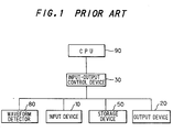
- FIG.1 is a block diagram showing a conventional waveform analyzer.
- the waveform analyzer comprises an input device 10, an output device 20, an input-output control device 30, a storage device 50, a waveform detector 80 and CPU 90 which has functions of filtering, Fourier analysis and the like.
- a waveform to be analyzed which is detected by the waveform detector 80, is supplied through the input-output control device 30 to CPU 90, where a waveform analysis is conducted by using the filtering and Fourier analysis, then the result of the waveform analysis is stored in the storage device 50 and is output through the output device 20 as an analysis result of the spectrum analyzer.
- an original data(measured data) is converted into a frequency domain, and the frequency and the corresponding frequency information composed of amplitude and phase information are waveform-analyzed only by the Fourier analysis, i.e., all things are discussed by converting into the frequency domain. Therefore, it has a demerit that information as to time domain and spacial position is lost.
- the Fourier spectrum is broadened, therefore it becomes difficult to catch the characteristics in time domain that are included in the original data.
- the filtering process has to be conducted in frequency domain or time domain.
- the setting of the filtering process parameter which determines which frequency corresponding component is removed or reduced, depends on operator's experience.
- FIGS.2A to 2F show waveforms in the filtering process. As shown in FIGS.2A to 2F, it can be appreciated that the waveform after the filtering becomes smooth as the cut-off frequency(fp) becomes low since the higher frequency component is suppressed. However, one cannot judge which waveform is related with the circuit operation and should be extracted.
- a Fourier transform which is partially conducted in a section where a pulse exists, i.e., a Fourier transform with a window function, and a short-time Fourier transform etc.
- These techniques can provide some information as to time domain, whereby the setting of the filtering process parameter can be suggested.
- the frequency precision will be lost, or, if frequency precision is enhanced, the time information will be lost. Thus, they must have so-called 'uncertainty'.
- a waveform analyzer comprises:
- a waveform analyzer comprises:
- a waveform analyzer comprises:
- a waveform analyzer comprises:
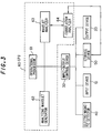
- FIG.3 A waveform analyzer in the preferred embodiment will be explained in FIG.3, wherein like parts are indicated by like reference numerals as used in FIG.1.
- the waveform analyzer comprises an input device 10, an output device 20, an input-output control device 30, an electromagnetic detector 40, a storage device 50 and CPU 60.
- CPU 60 has functions of wavelet analysis, correlation analysis etc., which comprises an operational processor 61, an analyzing wavelet generator 62, a wavelet analyzer 63 and a correlation analyzer 64.
- the wavelet analysis is employed as a method of analyzing measured data.
- the Fourier analysis is used to get the frequency information, when the wavelet analysis is employed, measured data can be analyzed on both time domain and frequency domain or on both space frequency and space position domain.
- FIG.4 is a flow chart for explaining an operation in the waveform analyzer in FIG.3, where a measured data is analyzed on both frequency domain and time domain.
- a measured data is collected by the electromagnetic detector 40 from EUT(a device to be measured) 71 (Step 72).
- the measured data is input through the input-output control device 30 to the wavelet analyzer 63 in CPU 60 and stored in the storage device 50. Meanwhile, the measured data may be input through the input device as it is or after it is processed.
- a Daubechies's analyzing wavelet which is produced as an orthogonal analyzing wavelet by the analyzing wavelet generator 62 in CPU 60, is input to the wavelet analyzer 63, where the discrete wavelet waveform analysis of the measured data is conducted(Step 73).
- Equation (1) means that, if input data has constant values, the solution is always zero.
- Equation (2) means that, even when input data increases monotonously, the solution is always zero.
- the solution has a value other than zero, thereby being detectable.
- the wavelet analysis is researched as a spectrum analysis, by which a place where a peculiarity( discontinuity, discontinuity of differential coefficient) occurs can be specified.
- the Daubechies's analyzing wavelet is one of orthogonal wavelets, whereby the whole can be reconstituted by a partial space defined by the direct sum resolution.
- data vector is taken by an exponent of two as the Fourier transform
- a partial space where a parallel movement and an enlargement/reduction is conducted as a unit of an exponent of two can be obtained.
- This corresponds to the multiple resolution analysis in which data vector is observed while changing the resolution.
- a high-speed transformation can be achieved as the Fourier transform.
- the analyzing wavelet generator 62 may produce the other kind of orthogonal wavelets.
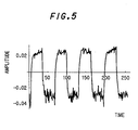
- the waveform in FIG.5 is wavelet-transformed by the wavelet analyzer, being resolved into the respective spectra(wavelet spectra) corresponding to the order of wavelet. This order corresponds to the frequency in the Fourier transform.
- each of the wavelet spectra is processed by the inverse wavelet transform to reproduce a waveform of time domain after the wavelet analysis.
- FIGS.6A to 6H show the respective waveform components resolved after the reproduction of waveforms of time domain.
- the operator analyzes the respective time waveform components and selects waveforms that appear to relate with the circuit operation, then, by adding them in the operational processor 61, a target waveform can be extracted by removing noise components.
- FIG.7 shows a composite waveform in which the resolved waveforms of the first order to the fifth order in FIGS.6A to 6E are added up. It will be appreciated that the harmonic noise is removed and the essential waveform is reproduced.
- the filtering effect equal to that of a low-pass filter can be obtained.
- the filtering effect equal to that of a high-pass filter can be obtained.
- the filtering effect equal to that of a band-pass filter can be obtained.
- the operator can perform the filtering while observing a time waveform and keeping the information of the original measured waveform, whereby waveforms related with the circuit operation can be selected.
- the selection of filter characteristic and until which order component to be added up can be conducted by the inputting from the input device 10 through the input-output device 30 to CPU 60.
- the correlation analyzer 64 in CPU 60 the correlation analysis is conducted between the original measured waveform output from the storage device 50 and the respective order waveforms to be wavelet-analyzed which are output from the wavelet analyzer 63( Step 74).
- each order of waveform to be wavelet-transformed is represented by g(t) and their wavelet coefficient vectors are Tf(a) and Tg(a), respectively
- Tf(a ⁇ )
- Tf(a ⁇ ) represent vectors obtained by removing their averages from the vectors Tf(a), Tg(a), respectively.
- FIG.8 shows a result of the correlation analysis by the correlation analyzer 64 in CPU 60 in which the above method is used.
- the magnitude of the correlation coefficient is in the order of third, sixth, fourth, eighth, seventh, fifth, second and first resolved waveforms.
- the bigger the correlation coefficient of wavelet solution waveform is, the more essential component of the original measured waveform it includes.
- the magnitude of correlation coefficient is identified( Step 75 in FIG.4 ), then, based on the identified result, the rearrangement according to the magnitude of correlation coefficient is conducted( Step 76 in FIG.4 ), selecting correlation coefficients bigger than a predetermined threshold value, adding up the resolved waveforms corresponding to the selected correlation coefficients. For example, if the correlation coefficients bigger than the threshold value belong to the third, sixth and fourth resolved waveforms, the composite waveform that these resolved waveforms are added up is as shown in FIG.9, where the noise components related with lower correlation coefficients can be removed to provide an essential waveform.
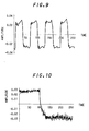
- the operational processor 61 may cut out a limited time section of the measured waveform as shown in FIG.10, thereafter performing the wavelet analysis and correlation analysis as described above.
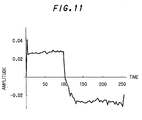
- the composite waveform that the first to fifth resolved waveforms with bigger correlation coefficients after the correlation analysis between the original measured waveform and wavelet-analyzed waveforms are added up is as shown in FIG.11, where the noise components related with lower correlation coefficients to the circuit operation can be removed.
- an electromagnetic intensity distribution( two-dimensional distribution) can be also processed by the filtering by similar wavelet analysis and correlation analysis.
Landscapes
- Physics & Mathematics (AREA)
- Electromagnetism (AREA)
- General Physics & Mathematics (AREA)
- Measurement Of Resistance Or Impedance (AREA)
- Testing Electric Properties And Detecting Electric Faults (AREA)
- Tests Of Electronic Circuits (AREA)
Applications Claiming Priority (2)
| Application Number | Priority Date | Filing Date | Title |
|---|---|---|---|
| JP15107/96 | 1996-01-31 | ||
| JP8015107A JP2735064B2 (ja) | 1996-01-31 | 1996-01-31 | 波形解析装置 |
Publications (2)
| Publication Number | Publication Date |
|---|---|
| EP0787995A2 true EP0787995A2 (de) | 1997-08-06 |
| EP0787995A3 EP0787995A3 (de) | 1998-11-18 |
Family
ID=11879623
Family Applications (1)
| Application Number | Title | Priority Date | Filing Date |
|---|---|---|---|
| EP97101497A Withdrawn EP0787995A3 (de) | 1996-01-31 | 1997-01-30 | Wellenformanalysator |
Country Status (3)
| Country | Link |
|---|---|
| US (1) | US5784285A (de) |
| EP (1) | EP0787995A3 (de) |
| JP (1) | JP2735064B2 (de) |
Cited By (1)
| Publication number | Priority date | Publication date | Assignee | Title |
|---|---|---|---|---|
| CN118444019A (zh) * | 2024-04-28 | 2024-08-06 | 深圳市友研电子有限公司 | 一种高频变压器的测试方法、装置、终端设备和存储介质 |
Families Citing this family (45)
| Publication number | Priority date | Publication date | Assignee | Title |
|---|---|---|---|---|
| US6327394B1 (en) * | 1998-07-21 | 2001-12-04 | International Business Machines Corporation | Apparatus and method for deriving temporal delays in integrated circuits |
| JP3730435B2 (ja) | 1999-03-26 | 2006-01-05 | 株式会社東芝 | 波形信号解析装置 |
| JP4028140B2 (ja) * | 1999-07-14 | 2007-12-26 | 松下電器産業株式会社 | 不要輻射解析方法 |
| US6957172B2 (en) * | 2000-03-09 | 2005-10-18 | Smartsignal Corporation | Complex signal decomposition and modeling |
| WO2001067262A1 (en) | 2000-03-09 | 2001-09-13 | Smartsignal Corporation | Generalized lensing angular similarity operator |
| US6556939B1 (en) | 2000-11-22 | 2003-04-29 | Smartsignal Corporation | Inferential signal generator for instrumented equipment and processes |
| US6975962B2 (en) * | 2001-06-11 | 2005-12-13 | Smartsignal Corporation | Residual signal alert generation for condition monitoring using approximated SPRT distribution |
| US7099417B2 (en) * | 2001-12-28 | 2006-08-29 | Agilent Technologies, Inc. | Trace video filtering using wavelet de-noising techniques |
| AU2003237796A1 (en) * | 2002-01-24 | 2003-09-02 | Matsushita Electric Industrial Co., Ltd. | Method of and system for power line carrier communications |
| US7653255B2 (en) | 2004-06-02 | 2010-01-26 | Adobe Systems Incorporated | Image region of interest encoding |
| US7317309B2 (en) * | 2004-06-07 | 2008-01-08 | Advantest Corporation | Wideband signal analyzing apparatus, wideband period jitter analyzing apparatus, and wideband skew analyzing apparatus |
| US7639886B1 (en) | 2004-10-04 | 2009-12-29 | Adobe Systems Incorporated | Determining scalar quantizers for a signal based on a target distortion |
| US7471652B2 (en) * | 2004-12-16 | 2008-12-30 | Tektronix, Inc. | Real-time RF/IF signature trigger |
| JP4619402B2 (ja) * | 2005-02-01 | 2011-01-26 | 株式会社日立国際電気 | スペクトル解析方法、歪検出装置、歪補償増幅装置 |
| JP4813128B2 (ja) * | 2005-08-25 | 2011-11-09 | 学校法人日本大学 | 機能的近赤外分光装置の信号解析装置、機能的近赤外分光装置並びにプログラム |
| US7668262B2 (en) * | 2005-10-21 | 2010-02-23 | Samsung Electro-Mechanics | Systems, methods, and apparatuses for coarse spectrum-sensing modules |
| US8085830B2 (en) * | 2006-01-27 | 2011-12-27 | Leviton Manufacturing Co., Inc. | LAN by ultra-wideband system and method |
| US20070198748A1 (en) * | 2006-02-01 | 2007-08-23 | Leviton Manufacturing Co., Inc. | Power line communication hub system and method |
| US8275577B2 (en) | 2006-09-19 | 2012-09-25 | Smartsignal Corporation | Kernel-based method for detecting boiler tube leaks |
| US7860197B2 (en) * | 2006-09-29 | 2010-12-28 | Samsung Electro-Mechanics | Spectrum-sensing algorithms and methods |
| US8311774B2 (en) | 2006-12-15 | 2012-11-13 | Smartsignal Corporation | Robust distance measures for on-line monitoring |
| JP4908185B2 (ja) * | 2006-12-25 | 2012-04-04 | 三菱電機株式会社 | レーダ波の識別装置 |
| US8605091B2 (en) * | 2008-04-18 | 2013-12-10 | Leviton Manufacturing Co., Inc. | Enhanced power distribution unit with self-orienting display |
| JP4768778B2 (ja) * | 2008-05-26 | 2011-09-07 | 株式会社東芝 | 変調方式推定装置及び方法 |
| DE102008002946B4 (de) * | 2008-07-16 | 2010-04-08 | Lear Corporation Gmbh | Verfahren zum Detektieren eines Fehlers auf einer Datenleitung |
| JP5295679B2 (ja) * | 2008-08-01 | 2013-09-18 | 株式会社キーエンス | 波形観測装置 |
| US20100198535A1 (en) * | 2009-02-03 | 2010-08-05 | Leviton Manufacturing Co., Inc. | Power distribution unit monitoring network and components |
| US8755944B2 (en) * | 2009-11-13 | 2014-06-17 | Leviton Manufacturing Co., Inc. | Electrical switching module |
| US8463453B2 (en) | 2009-11-13 | 2013-06-11 | Leviton Manufacturing Co., Inc. | Intelligent metering demand response |
| US8324761B2 (en) * | 2009-11-13 | 2012-12-04 | Leviton Manufacturing Co., Inc. | Electrical switching module |
| JP5552321B2 (ja) * | 2010-01-08 | 2014-07-16 | キヤノン株式会社 | 電磁波の測定装置及び方法 |
| JP5596982B2 (ja) * | 2010-01-08 | 2014-10-01 | キヤノン株式会社 | 電磁波の測定装置及び方法 |
| US8558504B2 (en) * | 2010-01-11 | 2013-10-15 | Leviton Manufacturing Co., Inc. | Electric vehicle supply equipment with timer |
| US20110169447A1 (en) * | 2010-01-11 | 2011-07-14 | Leviton Manufacturing Co., Inc. | Electric vehicle supply equipment |
| EP2523625B1 (de) * | 2010-01-14 | 2017-03-08 | PhysIQ Inc. | Multivariater restgrössen-gesundheitsindex zur überwachung der menschlichen gesundheit |
| US8633678B2 (en) | 2011-05-10 | 2014-01-21 | Leviton Manufacturing Co., Inc. | Electric vehicle supply equipment with over-current protection |
| US9250625B2 (en) | 2011-07-19 | 2016-02-02 | Ge Intelligent Platforms, Inc. | System of sequential kernel regression modeling for forecasting and prognostics |
| US9256224B2 (en) | 2011-07-19 | 2016-02-09 | GE Intelligent Platforms, Inc | Method of sequential kernel regression modeling for forecasting and prognostics |
| US8620853B2 (en) | 2011-07-19 | 2013-12-31 | Smartsignal Corporation | Monitoring method using kernel regression modeling with pattern sequences |
| US8660980B2 (en) | 2011-07-19 | 2014-02-25 | Smartsignal Corporation | Monitoring system using kernel regression modeling with pattern sequences |
| US8736193B2 (en) | 2011-12-22 | 2014-05-27 | Leviton Manufacturing Company, Inc. | Threshold-based zero-crossing detection in an electrical dimmer |
| US8664886B2 (en) | 2011-12-22 | 2014-03-04 | Leviton Manufacturing Company, Inc. | Timer-based switching circuit synchronization in an electrical dimmer |
| DE102013207464B4 (de) * | 2013-04-24 | 2023-07-13 | Rohde & Schwarz Gmbh & Co. Kg | Messverfahren und Messgerät zur Vermessung von breitbandigen Messsignalen |
| US9681526B2 (en) | 2014-06-11 | 2017-06-13 | Leviton Manufacturing Co., Inc. | Power efficient line synchronized dimmer |
| US20250152094A1 (en) | 2022-01-05 | 2025-05-15 | Prolaio, Inc. | System and method for monitoring an efficacy of a treatment for a cardiac condition |
Family Cites Families (2)
| Publication number | Priority date | Publication date | Assignee | Title |
|---|---|---|---|---|
| FR2648567B1 (fr) * | 1989-05-24 | 1991-10-04 | Inst Nat Sante Rech Med | Procede de traitement numerique d'un signal par transformation reversible en ondelettes |
| US5262958A (en) * | 1991-04-05 | 1993-11-16 | Texas Instruments Incorporated | Spline-wavelet signal analyzers and methods for processing signals |
-
1996
- 1996-01-31 JP JP8015107A patent/JP2735064B2/ja not_active Expired - Fee Related
-
1997
- 1997-01-30 EP EP97101497A patent/EP0787995A3/de not_active Withdrawn
- 1997-01-31 US US08/792,732 patent/US5784285A/en not_active Expired - Fee Related
Non-Patent Citations (1)
| Title |
|---|
| None |
Cited By (1)
| Publication number | Priority date | Publication date | Assignee | Title |
|---|---|---|---|---|
| CN118444019A (zh) * | 2024-04-28 | 2024-08-06 | 深圳市友研电子有限公司 | 一种高频变压器的测试方法、装置、终端设备和存储介质 |
Also Published As
| Publication number | Publication date |
|---|---|
| JPH09211040A (ja) | 1997-08-15 |
| JP2735064B2 (ja) | 1998-04-02 |
| US5784285A (en) | 1998-07-21 |
| EP0787995A3 (de) | 1998-11-18 |
Similar Documents
| Publication | Publication Date | Title |
|---|---|---|
| EP0787995A2 (de) | Wellenformanalysator | |
| US10677957B2 (en) | Method for random noise reduction from MRS oscillating signal using joint algorithms of EMD and TFPF | |
| US7099417B2 (en) | Trace video filtering using wavelet de-noising techniques | |
| US7908103B2 (en) | System and methods for determining masking signals for applying empirical mode decomposition (EMD) and for demodulating intrinsic mode functions obtained from application of EMD | |
| US20240088657A1 (en) | Fractional domain noise reduction method for power signal | |
| Bialasiewicz et al. | Wavelet-based approach to evaluation of signal integrity | |
| Kolláth | Chaotic Behaviour in the Light Variation of the Rv-Tauri Star R-Scuti | |
| Il et al. | An appropriate thresholding method of wavelet denoising for dropping ambient noise | |
| CN110531420A (zh) | 一种地震数据中工业干扰噪声无损分离方法 | |
| Meena et al. | Cross-term suppression in the Wigner-Ville distribution using variational mode decomposition | |
| Gratkowski et al. | Time–frequency filtering of MEG signals with matching pursuit | |
| US7457756B1 (en) | Method of generating time-frequency signal representation preserving phase information | |
| CN117373484B (zh) | 一种基于特征变换的开关柜声纹故障检测方法 | |
| US5295086A (en) | Method of producing noise free frequency spectrum signals | |
| Hassanpour | Improved SVD-based technique for enhancing the time-frequency representation of signals | |
| Bracale et al. | Optimal evaluation of waveform distortion indices with Prony and root music methods | |
| Musaruddin et al. | Signal segmentation of fault records based on Empirical Mode Decomposition | |
| Taranenko et al. | Optimizing the algorithm of wavelet packet signal filtering | |
| JPH0961475A (ja) | Emc解析エキスパートシステム | |
| Cao et al. | Suppression method of MT interference noise based on marginal spectrum and blind source separation | |
| Biswal et al. | Time frequency analysis and FPGA implementation of modified S-transform for de-noising | |
| Litvinenko et al. | Noise nature investigation of sporadic Jovian decameter emission | |
| Leonowicz et al. | Analysis of traction system time-varying signals using ESPRIT subspace spectrum estimation method | |
| Ghaemi et al. | Voltage notch indices determination using wavelet transform | |
| Leonowicz et al. | Spectrum estimation methods for signal analysis in the supply system of DC arc furnace |
Legal Events
| Date | Code | Title | Description |
|---|---|---|---|
| PUAI | Public reference made under article 153(3) epc to a published international application that has entered the european phase |
Free format text: ORIGINAL CODE: 0009012 |
|
| AK | Designated contracting states |
Kind code of ref document: A2 Designated state(s): DE GB |
|
| PUAL | Search report despatched |
Free format text: ORIGINAL CODE: 0009013 |
|
| AK | Designated contracting states |
Kind code of ref document: A3 Designated state(s): DE GB |
|
| 17P | Request for examination filed |
Effective date: 19981009 |
|
| 17Q | First examination report despatched |
Effective date: 19990510 |
|
| GRAP | Despatch of communication of intention to grant a patent |
Free format text: ORIGINAL CODE: EPIDOSNIGR1 |
|
| STAA | Information on the status of an ep patent application or granted ep patent |
Free format text: STATUS: THE APPLICATION HAS BEEN WITHDRAWN |
|
| 18W | Application withdrawn |
Effective date: 20040413 |