EP0785332B1 - Disposif de positionnement angulaire d'une masse par rapport à un axe horizontal de support et appareil d'éclairage équipé d'un tel dispositif - Google Patents
Disposif de positionnement angulaire d'une masse par rapport à un axe horizontal de support et appareil d'éclairage équipé d'un tel dispositif Download PDFInfo
- Publication number
- EP0785332B1 EP0785332B1 EP97400058A EP97400058A EP0785332B1 EP 0785332 B1 EP0785332 B1 EP 0785332B1 EP 97400058 A EP97400058 A EP 97400058A EP 97400058 A EP97400058 A EP 97400058A EP 0785332 B1 EP0785332 B1 EP 0785332B1
- Authority
- EP
- European Patent Office
- Prior art keywords
- support arm
- axis
- arm
- balancing
- positioning device
- Prior art date
- Legal status (The legal status is an assumption and is not a legal conclusion. Google has not performed a legal analysis and makes no representation as to the accuracy of the status listed.)
- Expired - Lifetime
Links
- 230000010355 oscillation Effects 0.000 claims description 14
- 239000000725 suspension Substances 0.000 claims description 14
- 230000006835 compression Effects 0.000 claims description 13
- 238000007906 compression Methods 0.000 claims description 13
- 238000006073 displacement reaction Methods 0.000 claims description 8
- 229920001971 elastomer Polymers 0.000 claims description 3
- 230000002035 prolonged effect Effects 0.000 claims 2
- 239000000806 elastomer Substances 0.000 claims 1
- 238000010276 construction Methods 0.000 description 3
- 230000003042 antagnostic effect Effects 0.000 description 2
- 210000000056 organ Anatomy 0.000 description 2
- 238000012550 audit Methods 0.000 description 1
- 230000000295 complement effect Effects 0.000 description 1
- 239000004020 conductor Substances 0.000 description 1
- 238000012886 linear function Methods 0.000 description 1
- 230000014759 maintenance of location Effects 0.000 description 1
- 238000004904 shortening Methods 0.000 description 1
Images

Classifications
-
- E—FIXED CONSTRUCTIONS
- E05—LOCKS; KEYS; WINDOW OR DOOR FITTINGS; SAFES
- E05D—HINGES OR SUSPENSION DEVICES FOR DOORS, WINDOWS OR WINGS
- E05D11/00—Additional features or accessories of hinges
- E05D11/10—Devices for preventing movement between relatively-movable hinge parts
- E05D11/1028—Devices for preventing movement between relatively-movable hinge parts for maintaining the hinge in two or more positions, e.g. intermediate or fully open
- E05D11/105—Devices for preventing movement between relatively-movable hinge parts for maintaining the hinge in two or more positions, e.g. intermediate or fully open the maintaining means acting perpendicularly to the pivot axis
-
- E—FIXED CONSTRUCTIONS
- E05—LOCKS; KEYS; WINDOW OR DOOR FITTINGS; SAFES
- E05F—DEVICES FOR MOVING WINGS INTO OPEN OR CLOSED POSITION; CHECKS FOR WINGS; WING FITTINGS NOT OTHERWISE PROVIDED FOR, CONCERNED WITH THE FUNCTIONING OF THE WING
- E05F1/00—Closers or openers for wings, not otherwise provided for in this subclass
- E05F1/08—Closers or openers for wings, not otherwise provided for in this subclass spring-actuated, e.g. for horizontally sliding wings
- E05F1/10—Closers or openers for wings, not otherwise provided for in this subclass spring-actuated, e.g. for horizontally sliding wings for swinging wings, e.g. counterbalance
- E05F1/12—Mechanisms in the shape of hinges or pivots, operated by springs
- E05F1/1246—Mechanisms in the shape of hinges or pivots, operated by springs with a coil spring perpendicular to the pivot axis
-
- F—MECHANICAL ENGINEERING; LIGHTING; HEATING; WEAPONS; BLASTING
- F16—ENGINEERING ELEMENTS AND UNITS; GENERAL MEASURES FOR PRODUCING AND MAINTAINING EFFECTIVE FUNCTIONING OF MACHINES OR INSTALLATIONS; THERMAL INSULATION IN GENERAL
- F16F—SPRINGS; SHOCK-ABSORBERS; MEANS FOR DAMPING VIBRATION
- F16F15/00—Suppression of vibrations in systems; Means or arrangements for avoiding or reducing out-of-balance forces, e.g. due to motion
- F16F15/28—Counterweights, i.e. additional weights counterbalancing inertia forces induced by the reciprocating movement of masses in the system, e.g. of pistons attached to an engine crankshaft; Attaching or mounting same
-
- E—FIXED CONSTRUCTIONS
- E05—LOCKS; KEYS; WINDOW OR DOOR FITTINGS; SAFES
- E05Y—INDEXING SCHEME ASSOCIATED WITH SUBCLASSES E05D AND E05F, RELATING TO CONSTRUCTION ELEMENTS, ELECTRIC CONTROL, POWER SUPPLY, POWER SIGNAL OR TRANSMISSION, USER INTERFACES, MOUNTING OR COUPLING, DETAILS, ACCESSORIES, AUXILIARY OPERATIONS NOT OTHERWISE PROVIDED FOR, APPLICATION THEREOF
- E05Y2900/00—Application of doors, windows, wings or fittings thereof
- E05Y2900/20—Application of doors, windows, wings or fittings thereof for furniture, e.g. cabinets
-
- Y—GENERAL TAGGING OF NEW TECHNOLOGICAL DEVELOPMENTS; GENERAL TAGGING OF CROSS-SECTIONAL TECHNOLOGIES SPANNING OVER SEVERAL SECTIONS OF THE IPC; TECHNICAL SUBJECTS COVERED BY FORMER USPC CROSS-REFERENCE ART COLLECTIONS [XRACs] AND DIGESTS
- Y10—TECHNICAL SUBJECTS COVERED BY FORMER USPC
- Y10S—TECHNICAL SUBJECTS COVERED BY FORMER USPC CROSS-REFERENCE ART COLLECTIONS [XRACs] AND DIGESTS
- Y10S362/00—Illumination
- Y10S362/804—Surgical or dental spotlight
Definitions
- the present invention relates to a positioning device angular mass with respect to a horizontal support axis, and in particular to a device for positioning a lighting dome of a lighting fixture for operating room.
- Known devices for angular positioning of a mass relative to a horizontal support axis comprising a support arm intended to carry said mass and angularly movable mounted around said support axis, and a balancing member of said arm connected to it and cooperating with an elastic return member adapted to apply a force to a point integral with the support arm, so as to generate a moment of balancing of the mass around the support axis (O 1 ) opposing the moment generated by the weight of the latter, the assembly constituted by the balancing member and the elastic return member being mounted oscillating on an axis of oscillation parallel to the support axis and located at a fixed distance therefrom, so as to continuously orient itself towards said point (M) during angular movements of the support arm.
- a device of this type is described in document GB-A-920550, where the support axis and the point of application of the force are mounted stationary at the base of a suspension arm of the device.
- angular positioning devices lighting fixtures where the balancing member consists of a chain connected by one end to the support arm and by its other end to the elastic return member, the elastic return member being constituted by a fixed spring whose general axis is arranged perpendicular to the axis support, devices of this type are further equipped with a bevel gear constituted by a roller on which the chain rests, so that the force exerted by this on the spring is parallel to the longitudinal axis of the spring which whatever the position of the support arm.
- the devices of the above types do not allow stable angular positioning of the suspended mass around its horizontal support axis over 360 °.
- the invention aims to overcome these drawbacks by proposing a device stable angular positioning of a mass with respect to an axis horizontal support allowing regular angular displacement of the mass as well as a balancing thereof whatever its angular position.
- the axis of support consists of a shaft extending axially by a crankpin eccentric on which is articulated the balancing member.
- the invention also relates to an apparatus lighting for operating room including an arm suspension of an articulated prism lighting cupola on a ceiling lamp and on which is angularly mounted movable said lighting dome, characterized in that it includes an angular positioning device a mass as defined above for positioning angle and balancing of the dome relative to the suspension arm.
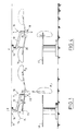
- FIG. 1 there is shown an apparatus operating room lighting, designated by the reference numeral 10, intended for precise positioning a volume of light on a patient lying on a table 11.
- the lighting apparatus 10 includes an arm suspension 12, in the form of a crank, of a dome lighting 14, of the prism type.
- the arm 12 can pivot around a main axis X-X articulated on a ceiling light 16, itself fixed to the ceiling 17 of the operating room by means of threaded rods.
- the lighting dome 14 is connected to the suspension arm 12 by a device for angular positioning of the dome 14 with respect to a horizontal support axis O 1 perpendicular to the plane of FIG. 1.
- This angular positioning device designated by the reference numeral 18, allows a surgeon to position the lighting dome 14, within the limits imposed by the ceiling 17, at any point of a circle with an axis O 1 , and in particular to move the lighting dome 14 from its position P1 shown in solid lines in Figure 1 to the positions P2 and P3 shown in dotted lines, depending on the type of surgical operation to be performed.
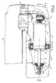
- the angular positioning device 18 of the dome 14 comprises a support arm 20 mounted angularly displaceable on the suspension arm 12, around the axis O 1 , and on which the lighting dome 14 is articulated around an axis horizontal 15 perpendicular to the arm 20, and a balancing member of the arm 20, not visible in this figure 1.
- the angular device 18 of the dome consists of the arm 20, the balancing member 22 and a member elastic return 24.
- the balancing member and the elastic return member 24 are arranged in a casing 26, fixed on the suspension arm 12 and on which the support arm 20 is angularly displaceable, relative to the horizontal support axis O 1 .
- the balancing member 22 is constituted by a rectilinear rod articulated around a hinge axis M, on a crank pin 28 extending parallel to the support axis O 1 and radially offset with respect thereto , as will be described in more detail later.
- the end of the rod 22 opposite the crank pin 28 has a threaded zone 30 on which is screwed a complementary nut 32 constituting a head on which is supported by the elastic return member 24.
- the organ return elastic 24 comprises a spring 34 disposed at the less in part in a cylindrical housing 36 provided with a end edge 38 open and a bottom 40 pierced with a orifice 42 for the passage of the threaded rod 22.
- the spring is compressed in an adjustable manner between the bottom 40 and nut 32.
- the spring 34 is a compression spring with conical type washers "Belleville”, but other types of springs can also be used, for example a spring visco-elastic rubber compression.
- the housing 36 is mounted oscillating in the casing 26 under the control of crankpin 28.
- the internal wall of the casing 26 is provided with two coaxial bearings 44, in which engage two lugs, such as 46, projecting radially from the outer wall of the housing 36, with interposition of ball bearings such as 48, for example bearings bearing and thrust combinations.
- the arm 20 is integral with one end 52 of a shaft 50 defining the support axis O 1 .
- This shaft 50 extends perpendicularly to the arm 20 in the direction of the balancing member 22 and of the elastic return member 24 and is extended axially by its other end 54, perpendicular to the arm 20, by the eccentric pin 28.
- the shaft 50 swivels in an extension cylindrical 56 of the casing 26 coaxial with this shaft, by means a set of ball bearings 58.
- the axis 50 is pierced with conduits 60 for the passage of electrical supply conductors of the lighting dome, not shown and of known type.
- the shaft 50 extends at level of its end 54 by the crank pin 28, on which is articulated the straight rod 22 and which defines the axis of articulation M.
- the shaft 50 constitutes a crank causing movement during its rotation rod 22, angular and along its own axis, in the housing 36.
- connection between the straight rod 22 and the crankpin 28 is provided in the following manner.
- the end of the straight rod 22 located at crankpin 28 has a thread 62 for the screwing of a generally cylindrical and pierced end piece 64 a transverse orifice 66 in which is inserted the pin 28.
- a set of bearings 68 is provided, consisting for example of combined bearing-thrust bearings.
- the connection between the end piece 64 and the crank pin 28 is supplemented by means of axial retention of the crank pin 28 in the end piece 64, designated by the reference 70 and of type known ( Figure 2).
- the housing 26 comprises a cover 72 fixed to the body 74 of the casing 26 by means fixing 76 of screws.
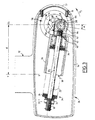
- the arm 20 forms an angle ⁇ with respect to the horizontal close to 10 ° (FIG. 1) and the straight line joining the support axis O 1 and the articulation axis M (FIG. 3) forms also this angle ⁇ with respect to the vertical.
- the weight of the dome 14 fixed on the support arm 20 exerts a moment on the support axis O 1 , which depends in a known manner on the angle that this support arm forms with the horizontal, c ' that is to say with the straight line defined by the horizontal support axis O 1 and the oscillation axis O 2 defined by the lugs 46 of the housing 36 received in the bearings 44.
- This moment is maximum when the arm 20 is in one of the horizontal positions and zero when this arm is located in a vertical position, that is to say perpendicular to the straight line joining the two axes O 1 and O 2 .
- the rod 22, cooperating with the spring 34 exerts an antagonistic balancing moment opposing the moment generated by the dome 14.
- this antagonistic moment is proportional to the shortening of the spring 34, that is to say ie a linear function of the distance between the axes O 2 and M ( Figure 3).
- the shaft 50 causes the crank pin 28 to rotate in the direction designated by the arrow F1 in FIG. 3 and the displacement of the straight rod 22 towards a position along the right joining the axes O 1 and O 2 , that is to say horizontally, which causes the compression of the spring 34.
- the rectilinear rod 22 oscillates relative to its axis of oscillation O 2 .
- the assembly constituted by the rectilinear rod 22 and the elastic return member 24 is oriented continuously, whatever the angular displacement of the support arm 20, along the line defined by the axis of oscillation O 2 and the articulation axis M of the straight rod 22.
- the device which has just been described therefore makes it possible to permanently position and stabilize the support arm 20 over 360 ° relative to the support axis O 1 .
- the lateral deflection of the lighting dome 14 has been preferred to upward travel, so you can cover a larger lighting area.
- the casing 26 is articulated around the second vertical pivot axis YY (FIG. 3) of the suspension arm 12, this axis YY being offset by a distance d from the support axis O 1 .
- the displacement of the dome between two any positions are performed on a regular basis and precise, since all movements are guided directly by bearings interposed between the members constituting the positioning device 18.
- the assembly consisting of the balancing member and the elastic member is mounted oscillating in the casing on which is articulated the support arm.
- the balancing member and the member elastic return are mounted oscillating in the support arm 82.
- the support arm 82 is angularly mounted movable around a shaft 84 secured by one of its ends of a support member 86 for the arm, connected to the suspension arm of the lighting fixture.
- the support arm 82 is angularly movable with respect to the support member 86 and, as previously, the end of the shaft 84, opposite to the support member 86, is extended axially by a eccentric pin 88 on which the organ is articulated balancing 80.
Landscapes
- Engineering & Computer Science (AREA)
- General Engineering & Computer Science (AREA)
- Mechanical Engineering (AREA)
- Physics & Mathematics (AREA)
- Acoustics & Sound (AREA)
- Aviation & Aerospace Engineering (AREA)
- Transmission Devices (AREA)
- Non-Portable Lighting Devices Or Systems Thereof (AREA)
- Lighting Device Outwards From Vehicle And Optical Signal (AREA)
Description
- l'organe élastique de rappel comporte un ressort dispose au moins en partie dans un boítier monté oscillant sur ledit axe d'oscillation et muni d'un fond délimitant une surface d'appui pour une zone d'extrémité du ressort, dont la zone d'extrémité opposée coopère avec l'organe d'équilibrage du bras de soutien ;
- l'organe d'équilibrage comporte une tige rectiligne traversant un orifice ménagé dans le fond du boítier et axialement déplaçable dans celui-ci sous la commande du bras de soutien ;
- l'ensemble constitué par l'organe d'équilibrage et l'organe élastique de rappel est disposé dans un carter, ledit axe d'oscillation étant constitué de deux ergots s'engageant dans deux paliers respectifs, ménagés les uns dans la paroi externe du boítier et les autres dans la paroi interne du carter ;
- l'arbre se prolonge radialement en direction du maneton selon une direction sensiblement perpendiculaires ment au bras de soutien en vue d'exercer sur celui-ci, sous l'action de l'organe d'équilibrage, un moment d'équilibrage maximum lorsque le bras de soutien est dans une position horizontale et un moment d'équilibrage minimum lorsque le bras de soutien est dans une position verticale ;
- l'extrémité de l'arbre opposée au maneton est solidaire du bras de soutien ;
- le carter est intégré au bras de soutien, l'extrémité de l'arbre opposée au maneton étant solidaire d'un organe de soutien pour ledit bras ;
- le ressort est un ressort de compression à rondelles coniques de type "Belleville" ;
- le ressort est un ressort de compression à gomme visco-élastique ;
- l'ensemble constitué par l'organe d'équilibrage et l'organe élastique de rappel est en outre monté angulairement déplaçable autour d'un axe de pivotement perpendiculaire audit axe d'oscillation ;
- la masse est constituée par une coupole d'éclairage montée angulairement déplaçable sur le bras de soutien.
- la figure 1 est une vue schématique d'un appareil d'éclairage pour salle d'opération, équipé d'un dispositif selon l'invention, dans différentes positions angulaires de la coupole d'éclairage ;
- la figure 2 est une vue de dessus agrandie d'un détail de l'appareil d'éclairage de la figure 1, avec coupes partielles, montrant le dispositif de positionnement angulaire de la coupole ;
- la figure 3 est une vue en coupe de profil, suivant la ligne III-III, du dispositif de la figure 2 ;
- la figure 4 représente l'appareil d'éclairage de la figure 1 ayant subi une rotation de 180° par rapport à son axe vertical de pivotement ; et
- la figure 5 illustre un autre mode de réalisation du dispositif de positionnement angulaire de la coupole d'éclairage.
Claims (12)
- Dispositif de positionnement angulaire d'une masse (14) par rapport à un axe horizontal de support (O1), comprenant un bras de soutien (20;82) destiné à porter ladite masse (14) et monté angulairement déplaçable autour dudit axe de support (O1), et un organe d'équilibrage (22;80) dudit bras (20;82) relié à celui-ci et coopérant avec un organe élastique de rappel (24) adapté pour appliquer sur un point (M) solidaire du bras de soutien une force, de façon à générer un moment d'équilibrage de la masse autour de l'axe de support (O1) s'opposant au moment engendré par le poids de celle-ci, l'ensemble constitué par l'organe d'équilibrage (22;80) et l'organe élastique de rappel (24) étant monté oscillant sur un axe d'oscillation (O2) parallèle à l'axe de support (O1) et situé à une distance fixe de celui-ci, de façon à s'orienter en permanence vers ledit point (M) lors des déplacements angulaires du bras de soutien (20;82), caractérisé en ce que l'axe de support (O1) est constitué par un arbre (50;84) se prolongeant axialement par un maneton (28;88) excentré sur lequel est articulé l'organe d'équilibrage (22;80).
- Dispositif de positionnement selon la revendication 1, caractérisé en ce que l'organe élastique de rappel (24) comporte un ressort (34) disposé au moins en partie dans un boítier (36) monté oscillant sur ledit axe d'oscillation (O2) et muni d'un fond (40) délimitant une surface d'appui pour une zone d'extrémité du ressort (34), dont la zone d'extrémité opposée coopère avec l'organe d'équilibrage (22) du aras de soutien (20).
- Dispositif de positionnement selon la revendication 2, caractérisé en ce que l'organe d'équilibrage (22;80) comporte une tige rectiligne (22) traversant un orifice ménagé dans le fond du boítier et axialement déplaçable dans celui-ci sous la commande du bras de soutien (20;82).
- Dispositif de positionnement selon l'une des revendications 2 et 3, caractérisé en ce que l'ensemble constitué par l'organe d'équilibrage et l'organe élastique de rappel est disposé dans un carter (26), ledit axe d'oscillation (O2) étant constitué de deux ergots s'engageant dans deux paliers respectifs, ménagés les uns dans la paroi externe du boítier (36) et les autres dans la paroi interne du carter (26).
- Dispositif de positionnement selon l'une des revendications 1 à 4, caractérisé en ce que l'arbre (50;84) se prolonge radialement en direction du maneton (28;88) selon une direction sensiblement perpendiculaire au bras de soutien (20;82) en vue d'exercer sur celui-ci, sous l'action de l'organe d'équilibrage (22;80), un moment d'équilibrage maximum lorsque le bras de soutien (20;82) est dans une position horizontale et un moment d'équilibrage minimum lorsque le bras de soutien (20;82) est dans une position verticale.
- Dispositif de positionnement selon l'une des revendications précédentes, caractérisé en ce que l'extrémité de l'arbre (50) opposée au maneton (28) est solidaire du bras de soutien (20).
- Dispositif de positionnement selon l'une des revendications 4 et 5, caractérisé en ce que le carter est intégré au bras de soutien (82), l'extrémité de l'arbre (84) opposée au maneton (88) étant solidaire d'un organe de soutien pour ledit bras (82).
- Dispositif de positionnement selon l'une quelconque des revendications 2 à 7, caractérisé en ce que le ressort (34) est un ressort de compression à rondelles coniques de type "Belleville".
- Dispositif de positionnement selon l'une quelconque des revendications 2 à 7, caractérisé en ce que le ressort (34) est un ressort de compression à gomme visco-élastique.
- Dispositif de positionnement selon l'une quelconque des revendications précédentes, caractérisé en ce que l'ensemble constitué par l'organe d'équilibrage (22) et l'organe élastique de rappel (24) est en outre monté angulairement déplaçable autour d'un axe de pivotement (Y-Y) perpendiculaire audit axe d'oscillation (O2).
- Dispositif de positionnement selon l'une quelconque des revendications précédentes, caractérisé en ce que la masse est constituée par une coupole d'éclairage (14) montée angulairement déplaçable sur le bras de soutien (20).
- Appareil d'éclairage pour salle d'opération comprenant un bras de suspension (12) d'une coupole d'éclairage à prismes (14) articulé sur un plafonnier (16) et sur lequel est montée angulairement déplaçable ladite coupole d'éclairage (14), caractérisé en ce qu'il comporte un dispositif de positionnement angulaire d'une masse selon l'une quelconque des revendications 1 à 11 en vue du positionnement angulaire et de l'équilibrage de la coupole (14) par rapport au bras de suspension (12).
Applications Claiming Priority (2)
| Application Number | Priority Date | Filing Date | Title |
|---|---|---|---|
| FR9600623 | 1996-01-19 | ||
| FR9600623A FR2743856B1 (fr) | 1996-01-19 | 1996-01-19 | Dispositif de positionnement angulaire d'une masse par rapport a un axe horizontal de support et appareil d'eclairage equipe d'un tel dispositif |
Publications (2)
| Publication Number | Publication Date |
|---|---|
| EP0785332A1 EP0785332A1 (fr) | 1997-07-23 |
| EP0785332B1 true EP0785332B1 (fr) | 2000-12-27 |
Family
ID=9488283
Family Applications (1)
| Application Number | Title | Priority Date | Filing Date |
|---|---|---|---|
| EP97400058A Expired - Lifetime EP0785332B1 (fr) | 1996-01-19 | 1997-01-14 | Disposif de positionnement angulaire d'une masse par rapport à un axe horizontal de support et appareil d'éclairage équipé d'un tel dispositif |
Country Status (8)
| Country | Link |
|---|---|
| US (1) | US5971572A (fr) |
| EP (1) | EP0785332B1 (fr) |
| JP (1) | JPH11502667A (fr) |
| CA (1) | CA2216604A1 (fr) |
| DE (1) | DE69703752T2 (fr) |
| ES (1) | ES2154014T3 (fr) |
| FR (1) | FR2743856B1 (fr) |
| WO (1) | WO1997026433A1 (fr) |
Families Citing this family (6)
| Publication number | Priority date | Publication date | Assignee | Title |
|---|---|---|---|---|
| EP1148860A4 (fr) * | 1998-12-17 | 2002-10-09 | Getinge Castle Inc | Systeme d'eclairage concu notamment a des fins chirurgicales |
| DE19928835C1 (de) * | 1999-06-24 | 2001-01-11 | Draeger Medizintech Gmbh | Bewegliche medizinische Versorgungsvorrichtung |
| US10371411B2 (en) * | 2009-10-22 | 2019-08-06 | Nortek Air Solutions, Llc | Ceiling system with integrated equipment support structure |
| USD871588S1 (en) | 2016-04-21 | 2019-12-31 | Avail Medsystems, Inc. | Medical console |
| US20170316705A1 (en) | 2016-04-27 | 2017-11-02 | David Paul Schultz | System, Apparatus and Methods for Telesurgical Mentoring Platform |
| CN106704479A (zh) * | 2016-12-02 | 2017-05-24 | 上海航天设备制造总厂 | 一种二维随动的重力平衡装置 |
Family Cites Families (5)
| Publication number | Priority date | Publication date | Assignee | Title |
|---|---|---|---|---|
| GB920550A (en) * | 1960-12-12 | 1963-03-06 | Ritter Co Inc | Supporting mechanism for surgical operating lights |
| US4137669A (en) * | 1978-02-08 | 1979-02-06 | Sybron Corporation | Balancing mechanism for manhole covers |
| DE3767323D1 (de) * | 1986-03-07 | 1991-02-21 | Edelhoff Polytechnik | Container, vorzugsweise zur aufnahme von muell. |
| US5025359A (en) * | 1990-03-16 | 1991-06-18 | American Sterilizer Company | Counterbalanced arm for a lighthead |
| US5038520A (en) * | 1990-11-01 | 1991-08-13 | The Pfaudler Companies, Inc. | Manway lift assist |
-
1996
- 1996-01-19 FR FR9600623A patent/FR2743856B1/fr not_active Expired - Fee Related
-
1997
- 1997-01-14 WO PCT/FR1997/000062 patent/WO1997026433A1/fr not_active Ceased
- 1997-01-14 CA CA002216604A patent/CA2216604A1/fr not_active Abandoned
- 1997-01-14 JP JP9525735A patent/JPH11502667A/ja not_active Ceased
- 1997-01-14 DE DE69703752T patent/DE69703752T2/de not_active Expired - Lifetime
- 1997-01-14 EP EP97400058A patent/EP0785332B1/fr not_active Expired - Lifetime
- 1997-01-14 ES ES97400058T patent/ES2154014T3/es not_active Expired - Lifetime
- 1997-01-14 US US08/913,418 patent/US5971572A/en not_active Expired - Lifetime
Also Published As
| Publication number | Publication date |
|---|---|
| US5971572A (en) | 1999-10-26 |
| WO1997026433A1 (fr) | 1997-07-24 |
| ES2154014T3 (es) | 2001-03-16 |
| FR2743856B1 (fr) | 1998-02-27 |
| DE69703752D1 (de) | 2001-02-01 |
| CA2216604A1 (fr) | 1997-07-24 |
| EP0785332A1 (fr) | 1997-07-23 |
| DE69703752T2 (de) | 2001-05-10 |
| FR2743856A1 (fr) | 1997-07-25 |
| JPH11502667A (ja) | 1999-03-02 |
Similar Documents
| Publication | Publication Date | Title |
|---|---|---|
| FR2699595A1 (fr) | Dispositif de guidage en rotation d'un anneau de commande d'aubes pivotantes. | |
| FR2713330A1 (fr) | Dispositif de commande de vol. | |
| CA2439881A1 (fr) | Dispositif cinematique de support et de deplacement programmable d'un element terminal dans une machine ou un instrument | |
| FR2695616A1 (fr) | Frein de bicyclette à leviers articulés. | |
| FR2618108A1 (fr) | Dispositif de fixation de feu avant sur un vehicule | |
| FR2578472A1 (fr) | Perfectionnements aux robots industriels du type a structure spherique | |
| EP0832799B1 (fr) | Dispositif d'essuyage d'une vitre de véhicule automobile comportant un dispositif perfectionné d'orientation d'un arbre d'entraínement | |
| EP0388293A1 (fr) | Tendeur pour courroie de transmission de puissance | |
| FR2662215A1 (fr) | Dispositif de compression, en particulier pour le remplissage sous pression d'un reservoir. | |
| FR2769255A1 (fr) | Dispositif de maintien, de positionnement, ou de serrage | |
| EP0785332A1 (fr) | Disposif de positionnement angulaire d'une masse par rapport à un axe horizontal de support et appareil d'éclairage équipé d'un tel dispositif | |
| EP0270870B1 (fr) | Mécanisme pour actionner un clapet de dosage | |
| FR2627718A1 (fr) | Dispositif d'equilibrage des forces, notamment de pesanteur, agissant sur un bras de robot ou analogue | |
| EP0786376B1 (fr) | Projecteur comportant un dispositif de stabilisation du miroir | |
| EP0508841A1 (fr) | Bras d'essuie-glace, notamment pour véhicule à grande vitesse | |
| FR2559108A1 (fr) | Dispositif de reglage de l'orientation et de l'inclinaison d'un projecteur pour vehicules automobiles | |
| FR2810873A1 (fr) | Dispositif de liaison intervertebral | |
| FR2545760A1 (fr) | Dispositif de commande d'une navette d'imprimante | |
| EP1072366A1 (fr) | Dispositif transporteur | |
| CA2325868C (fr) | Ensemble comprenant un premier chassis et un deuxieme chassis pendulant lateralement par rapport au premier chassis, et vehicule ferroviaire correspondant | |
| EP1445169A1 (fr) | Pivot glissant d'une colonne de direction réglable de véhicule automobile | |
| EP0250294B1 (fr) | Dispositif d'essuie-glace, à balayage non circulaire | |
| EP0681080B1 (fr) | Dispositif d'arrêt pour ouvrant | |
| FR2533771A1 (fr) | Support de poulie de deroulage pour cable | |
| FR2506002A1 (fr) | Support d'arme legere |
Legal Events
| Date | Code | Title | Description |
|---|---|---|---|
| PUAI | Public reference made under article 153(3) epc to a published international application that has entered the european phase |
Free format text: ORIGINAL CODE: 0009012 |
|
| AK | Designated contracting states |
Kind code of ref document: A1 Designated state(s): DE ES GB IT NL SE |
|
| RAP1 | Party data changed (applicant data changed or rights of an application transferred) |
Owner name: ALM |
|
| 17P | Request for examination filed |
Effective date: 19980123 |
|
| 17Q | First examination report despatched |
Effective date: 19990618 |
|
| GRAG | Despatch of communication of intention to grant |
Free format text: ORIGINAL CODE: EPIDOS AGRA |
|
| GRAG | Despatch of communication of intention to grant |
Free format text: ORIGINAL CODE: EPIDOS AGRA |
|
| GRAH | Despatch of communication of intention to grant a patent |
Free format text: ORIGINAL CODE: EPIDOS IGRA |
|
| GRAH | Despatch of communication of intention to grant a patent |
Free format text: ORIGINAL CODE: EPIDOS IGRA |
|
| GRAA | (expected) grant |
Free format text: ORIGINAL CODE: 0009210 |
|
| AK | Designated contracting states |
Kind code of ref document: B1 Designated state(s): DE ES GB IT NL SE |
|
| PG25 | Lapsed in a contracting state [announced via postgrant information from national office to epo] |
Ref country code: SE Free format text: THE PATENT HAS BEEN ANNULLED BY A DECISION OF A NATIONAL AUTHORITY Effective date: 20001227 Ref country code: NL Free format text: LAPSE BECAUSE OF FAILURE TO SUBMIT A TRANSLATION OF THE DESCRIPTION OR TO PAY THE FEE WITHIN THE PRESCRIBED TIME-LIMIT Effective date: 20001227 |
|
| ITF | It: translation for a ep patent filed | ||
| REF | Corresponds to: |
Ref document number: 69703752 Country of ref document: DE Date of ref document: 20010201 |
|
| GBT | Gb: translation of ep patent filed (gb section 77(6)(a)/1977) |
Effective date: 20010124 |
|
| REG | Reference to a national code |
Ref country code: ES Ref legal event code: FG2A Ref document number: 2154014 Country of ref document: ES Kind code of ref document: T3 |
|
| NLV1 | Nl: lapsed or annulled due to failure to fulfill the requirements of art. 29p and 29m of the patents act | ||
| PLBE | No opposition filed within time limit |
Free format text: ORIGINAL CODE: 0009261 |
|
| STAA | Information on the status of an ep patent application or granted ep patent |
Free format text: STATUS: NO OPPOSITION FILED WITHIN TIME LIMIT |
|
| 26N | No opposition filed | ||
| REG | Reference to a national code |
Ref country code: GB Ref legal event code: IF02 |
|
| PGFP | Annual fee paid to national office [announced via postgrant information from national office to epo] |
Ref country code: ES Payment date: 20040119 Year of fee payment: 8 |
|
| PG25 | Lapsed in a contracting state [announced via postgrant information from national office to epo] |
Ref country code: ES Free format text: LAPSE BECAUSE OF NON-PAYMENT OF DUE FEES Effective date: 20050115 |
|
| REG | Reference to a national code |
Ref country code: ES Ref legal event code: FD2A Effective date: 20050115 |
|
| PGFP | Annual fee paid to national office [announced via postgrant information from national office to epo] |
Ref country code: DE Payment date: 20120123 Year of fee payment: 16 |
|
| PGFP | Annual fee paid to national office [announced via postgrant information from national office to epo] |
Ref country code: IT Payment date: 20120126 Year of fee payment: 16 Ref country code: GB Payment date: 20120120 Year of fee payment: 16 |
|
| GBPC | Gb: european patent ceased through non-payment of renewal fee |
Effective date: 20130114 |
|
| PG25 | Lapsed in a contracting state [announced via postgrant information from national office to epo] |
Ref country code: DE Free format text: LAPSE BECAUSE OF NON-PAYMENT OF DUE FEES Effective date: 20130801 |
|
| REG | Reference to a national code |
Ref country code: DE Ref legal event code: R119 Ref document number: 69703752 Country of ref document: DE Effective date: 20130801 |
|
| PG25 | Lapsed in a contracting state [announced via postgrant information from national office to epo] |
Ref country code: GB Free format text: LAPSE BECAUSE OF NON-PAYMENT OF DUE FEES Effective date: 20130114 |
|
| PG25 | Lapsed in a contracting state [announced via postgrant information from national office to epo] |
Ref country code: IT Free format text: LAPSE BECAUSE OF NON-PAYMENT OF DUE FEES Effective date: 20130114 |