EP0784996B1 - Vorrichtung und Verfahren zur Erzeugung eines synthetisierten Elektrokardiogramms - Google Patents
Vorrichtung und Verfahren zur Erzeugung eines synthetisierten Elektrokardiogramms Download PDFInfo
- Publication number
- EP0784996B1 EP0784996B1 EP96850200A EP96850200A EP0784996B1 EP 0784996 B1 EP0784996 B1 EP 0784996B1 EP 96850200 A EP96850200 A EP 96850200A EP 96850200 A EP96850200 A EP 96850200A EP 0784996 B1 EP0784996 B1 EP 0784996B1
- Authority
- EP
- European Patent Office
- Prior art keywords
- signals
- signal
- signal processing
- electrodes
- electrode
- Prior art date
- Legal status (The legal status is an assumption and is not a legal conclusion. Google has not performed a legal analysis and makes no representation as to the accuracy of the status listed.)
- Expired - Lifetime
Links
- 238000000034 method Methods 0.000 title claims description 37
- 238000012545 processing Methods 0.000 claims description 54
- 238000013528 artificial neural network Methods 0.000 claims description 30
- 230000000694 effects Effects 0.000 claims description 25
- 238000012546 transfer Methods 0.000 claims description 18
- 230000001131 transforming effect Effects 0.000 claims description 12
- 230000002194 synthesizing effect Effects 0.000 claims description 9
- 230000000747 cardiac effect Effects 0.000 claims description 8
- 230000000903 blocking effect Effects 0.000 claims description 7
- 230000008569 process Effects 0.000 claims description 6
- 238000012549 training Methods 0.000 claims description 3
- 230000000763 evoking effect Effects 0.000 claims description 2
- 238000002565 electrocardiography Methods 0.000 description 52
- 239000007943 implant Substances 0.000 description 38
- 230000002861 ventricular Effects 0.000 description 15
- 239000004020 conductor Substances 0.000 description 14
- 230000006870 function Effects 0.000 description 14
- 210000002620 vena cava superior Anatomy 0.000 description 13
- 238000012544 monitoring process Methods 0.000 description 12
- 230000001746 atrial effect Effects 0.000 description 11
- 210000002837 heart atrium Anatomy 0.000 description 9
- 230000003321 amplification Effects 0.000 description 6
- 238000003199 nucleic acid amplification method Methods 0.000 description 6
- 210000005241 right ventricle Anatomy 0.000 description 6
- 238000001514 detection method Methods 0.000 description 5
- 230000000638 stimulation Effects 0.000 description 5
- 230000009471 action Effects 0.000 description 3
- 230000002169 extracardiac Effects 0.000 description 3
- 238000001914 filtration Methods 0.000 description 3
- 238000002513 implantation Methods 0.000 description 3
- 208000028867 ischemia Diseases 0.000 description 3
- 238000005259 measurement Methods 0.000 description 3
- 230000037361 pathway Effects 0.000 description 3
- 238000000718 qrs complex Methods 0.000 description 3
- 210000005245 right atrium Anatomy 0.000 description 3
- 208000001871 Tachycardia Diseases 0.000 description 2
- 238000004458 analytical method Methods 0.000 description 2
- 230000006399 behavior Effects 0.000 description 2
- 230000036772 blood pressure Effects 0.000 description 2
- 238000010586 diagram Methods 0.000 description 2
- 238000012886 linear function Methods 0.000 description 2
- 210000003205 muscle Anatomy 0.000 description 2
- 230000004936 stimulating effect Effects 0.000 description 2
- 230000006794 tachycardia Effects 0.000 description 2
- 238000002560 therapeutic procedure Methods 0.000 description 2
- 206010049765 Bradyarrhythmia Diseases 0.000 description 1
- 208000000418 Premature Cardiac Complexes Diseases 0.000 description 1
- 102100026827 Protein associated with UVRAG as autophagy enhancer Human genes 0.000 description 1
- 101710102978 Protein associated with UVRAG as autophagy enhancer Proteins 0.000 description 1
- 208000009729 Ventricular Premature Complexes Diseases 0.000 description 1
- 206010047289 Ventricular extrasystoles Diseases 0.000 description 1
- 210000000577 adipose tissue Anatomy 0.000 description 1
- 210000000988 bone and bone Anatomy 0.000 description 1
- 208000006218 bradycardia Diseases 0.000 description 1
- 230000008859 change Effects 0.000 description 1
- 238000004891 communication Methods 0.000 description 1
- 230000000295 complement effect Effects 0.000 description 1
- 230000001419 dependent effect Effects 0.000 description 1
- 238000003745 diagnosis Methods 0.000 description 1
- 210000003238 esophagus Anatomy 0.000 description 1
- 208000019622 heart disease Diseases 0.000 description 1
- 230000006872 improvement Effects 0.000 description 1
- 230000005764 inhibitory process Effects 0.000 description 1
- 238000012986 modification Methods 0.000 description 1
- 230000004048 modification Effects 0.000 description 1
- 238000001615 p wave Methods 0.000 description 1
- 230000004044 response Effects 0.000 description 1
- 230000000717 retained effect Effects 0.000 description 1
- 230000002269 spontaneous effect Effects 0.000 description 1
- 238000007920 subcutaneous administration Methods 0.000 description 1
- 238000004441 surface measurement Methods 0.000 description 1
- 210000001519 tissue Anatomy 0.000 description 1
- 208000003663 ventricular fibrillation Diseases 0.000 description 1
- 206010047302 ventricular tachycardia Diseases 0.000 description 1
Images





Classifications
-
- A—HUMAN NECESSITIES
- A61—MEDICAL OR VETERINARY SCIENCE; HYGIENE
- A61N—ELECTROTHERAPY; MAGNETOTHERAPY; RADIATION THERAPY; ULTRASOUND THERAPY
- A61N1/00—Electrotherapy; Circuits therefor
- A61N1/18—Applying electric currents by contact electrodes
- A61N1/32—Applying electric currents by contact electrodes alternating or intermittent currents
- A61N1/36—Applying electric currents by contact electrodes alternating or intermittent currents for stimulation
- A61N1/362—Heart stimulators
- A61N1/365—Heart stimulators controlled by a physiological parameter, e.g. heart potential
- A61N1/368—Heart stimulators controlled by a physiological parameter, e.g. heart potential comprising more than one electrode co-operating with different heart regions
-
- A—HUMAN NECESSITIES
- A61—MEDICAL OR VETERINARY SCIENCE; HYGIENE
- A61B—DIAGNOSIS; SURGERY; IDENTIFICATION
- A61B5/00—Measuring for diagnostic purposes; Identification of persons
- A61B5/24—Detecting, measuring or recording bioelectric or biomagnetic signals of the body or parts thereof
- A61B5/316—Modalities, i.e. specific diagnostic methods
- A61B5/318—Heart-related electrical modalities, e.g. electrocardiography [ECG]
- A61B5/327—Generation of artificial ECG signals based on measured signals, e.g. to compensate for missing leads
-
- A—HUMAN NECESSITIES
- A61—MEDICAL OR VETERINARY SCIENCE; HYGIENE
- A61N—ELECTROTHERAPY; MAGNETOTHERAPY; RADIATION THERAPY; ULTRASOUND THERAPY
- A61N1/00—Electrotherapy; Circuits therefor
- A61N1/18—Applying electric currents by contact electrodes
- A61N1/32—Applying electric currents by contact electrodes alternating or intermittent currents
- A61N1/36—Applying electric currents by contact electrodes alternating or intermittent currents for stimulation
- A61N1/362—Heart stimulators
- A61N1/37—Monitoring; Protecting
- A61N1/3702—Physiological parameters
-
- A—HUMAN NECESSITIES
- A61—MEDICAL OR VETERINARY SCIENCE; HYGIENE
- A61N—ELECTROTHERAPY; MAGNETOTHERAPY; RADIATION THERAPY; ULTRASOUND THERAPY
- A61N1/00—Electrotherapy; Circuits therefor
- A61N1/18—Applying electric currents by contact electrodes
- A61N1/32—Applying electric currents by contact electrodes alternating or intermittent currents
- A61N1/38—Applying electric currents by contact electrodes alternating or intermittent currents for producing shock effects
- A61N1/39—Heart defibrillators
- A61N1/3956—Implantable devices for applying electric shocks to the heart, e.g. for cardioversion
- A61N1/3962—Implantable devices for applying electric shocks to the heart, e.g. for cardioversion in combination with another heart therapy
- A61N1/39622—Pacing therapy
Definitions
- the invention relates to a device and a method for signal processing of known intracardiac signals from electrodes in an implantable heart stimulator/defibrillator/monitoring system (an active implanted system) and a method for use of detected intracorporal cardiac signals and also to an active implant including such a device in whole or in part.
- Electrodes limb and chest electrodes
- the signals have to pass through tissue, muscles, bone and adipose tissue the signals are partly disguised and also the muscles in themselves display electrical activity which may hide or distort the signals from the heart.
- a complementary measure to the ECG is to transmit signals by telemetry from intracardial electrodes in the form of an IEGM, an intracardiac electrogram. This may be done e.g. in follow-ups after implantation and when possibly adjustment of controlling parameters in the active implant occurs.
- the IEGM is usually combined by the practitioner with the measuring of a surface ECG.
- the purpose of the method is to derive the VFT (Ventricular Fibrillation Threshold) indirectly from measurements of the PVCT (Premature Ventricular Contraction Threshold), MET (Multiple Extrasystole Threshold), and VTT (Ventricular Tachycardia Threshold).
- Stimulation pulses for the stimulation of the heart are given and also pulse trains intended to cause the above phenomena.
- the threshold is detected by incrementally giving the pulse trains a higher amplitude.
- the ECG used in this publication is measured by extracorporal means, i.e., by surface measurements, while the stimulation pulses and the pulse trains are applied via either cardiac catheter or in the esophagus.
- a method and an implantable pacemaker suited for Bradyarrhythmia therapy which stimulates and senses and obtains the ECG signal from the by stimulation evoked response in the heart, i.e. the QRS complex, is described in EP 605 244.
- the problem described therein is that of the large residual potential remaining across the bipolar electrodes.
- This problem is solved by processing the signals sensed by the ring and tip electrode of a typical pacemaker bipolar lead.
- the circuit senses each of these signals from the ring and tip electrodes in a unipolar mode.
- the sensed electrical signals are subsequently added to cancel or nullify the opposing residual potentials which remain on the ring and tip electrode post pacing.
- the common-potential ECG signal is added and presented for subsequent detection of the QRS complex. In this way the higher residual potential signals are removed prior to the subsequent signal processing and the low level ECG signal is retained. This is thus an adding procedure and not a processing of the signals in a differential mode.
- EP, A1,0 596 319 Another example of combinations of signals and the use of time of incidence for acceptance of true atrial events by combining signals from different electrodes and using a logic unit is found in EP, A1,0 596 319 in which a heart stimulator is described comprising a pulse generator and an electrode system which contains at least one bipolar electrode with one electrode arranged in the atrium and one electrode in the ventricle respectively, for detection of atrial and ventricular activity.
- Document WO-A-92/02171 discloses an apparatus configured to synthesize ECG signals. This document is considered to represent the most relevant prior art.
- Active implant Active implant , heart stimulator, heart monitor, defibrillator and other similar implanted units.
- SECG Synthesized surface electrocardiogram is a synthesized electrogram created from at least two IEGMs.
- ECG Surface electrogram a recording using limb and/or chest electrodes, i.e. extracorporal recordings.
- TIP Tip electrode pace and sensing electrode implanted in the ventricle or in the atrium.
- RING Ring electrode part of a bipolar electrode system. Can be implanted as a part of the ventricular and/or atrial electrode.
- RV Right ventricular defibrillation electrode.
- PATCH Epicardial patch subcutaneous patch, extracardial patch.
- Heart stimulator pacemaker, defibrillator.
- the object of the invention is to provide from the implanted electrodes of an active implant (pacer and/or a defibrillator and/or implanted monitoring systems) a type of ECG which in appearance can be substituted for a surface ECG and which may be used especially postoperatively and for follow-ups (repeated) after the implantation of a stimulator or the like or for e.g. checking the function of the same or for adjusting the parameters controlling the active implant or whenever a programmer is in contact with the active implant.
- an active implant pacer and/or a defibrillator and/or implanted monitoring systems
- Another object is to provide easier and faster follow-ups after an implantation without the use of additional extracorporal electrodes.
- Another object is to make possible the transmitting over the public telephone net of signals used by the practitioner for follow-ups and for diagnostic use by the practitioner located away from the patient having the active implant. Also the intent is to synthesize a surface ECG so that the practitioner will recognize the signals and be able to interpret the signals with his/her knowledge of the surface ECG.
- Another object of the invention is to make use of the signals from each electrode and to be able to exclude and/or lessen the effects of the information in the signal of electrical activity in the very close proximity to the electrode.
- Yet another object is to be able to better distinguish between paced and spontaneous heart activities such as: capture, inhibition, fusion beats, etc.
- a further object is to provide a diagnosis means to be used in diagnosing and detection of ischemia and in resolving which type of tachycardia is present in tachycardia cases.
- the indications of ischemia in the heart shown by the implanted electrodes should be easier to detect and also to counteract via the pacing of the heart. This can be the earliest warning that can be seen of ischemia or other heart diseases.
- Still another object is to find a means for registering of changes in the ECG in a person having an active implant, which changes will constitute contraindications or indications for adjustment of the rate responsive function in which case the rate will remain unchanged or adjusted in some other way indicated by analysis of the recorded ECG.
- the inventors have now surprisingly found that by interconnecting two or more intracardiac and/or extracardiac electrodes - electrically connecting the electrodes - measuring signals from these electrodes and thereafter expose these signals to signal processing a synthesized surface ECG may be obtained.
- This signal processing may comprise a treatment of the signals in which the signals are processed using methods such as neural network and/or fuzzy logic, and/or summation of processed signals.
- IEGM recordings between different electrodes in defibrillation and pacing systems show similarities to "surface ECG".
- the idea arose to measure signals between at least two groups of interconnected electrodes, where each group contains signals from at least one electrode.
- the problems solved according to the invention by using only in the heart implanted electrodes and/or implanted intra-corporal electrodes belonging to an active implant to create from measurements of electrical activity in the heart through signal processing a synthesized ECG which gives the same or other information as the standard surface ECG.
- Another problem which is solved according to the invention is that the necessity for placing electrodes on the patients surface and connecting these to the ECG machine no longer will be necessary since the signals from the implanted electrodes may be sensed using telemetry and this gives the possibility to relay these signals even by telephone from the patient to the physician, which may make a printout of the signals and analyse the ECG.
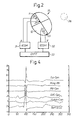
- Fig. 1 shows schematically an existing electrode configuration for registering of IEGM (intracardiac electrogram) between different implanted electrodes.
- IEGM intracardiac electrogram
- a heart 10 with two implanted unipolar electrodes 21, 23 in the atrium 11 and in the ventricle 12, respectively.
- extracardiac electrode 26 which may be the housing of the stimulator (can).
- Signals are measured between the can and electrodes 21, 23 giving an atrial IEGM A in unit (31) and a ventricular IEGM V unit (32).
- the differential signal between the two electrodes 21 and 23 gives a differential signal in unit (33).
- Units 31, 32, and 33 are the monitoring units for the IEGMs.
- Fig. 2 shows another example of an existing electrode configuration which may be used in accordance with the invention in the figure is shown a heart 10 with two implanted bipolar electrodes, each having a tip electrode 21 and 23 and a ring electrode 20 and 22 in the atrium 11 and the ventricle 12, respectively.
- the atrial IEGM is then measured in the unit 31 between the ring and the tip of the bipolar electrode in the atrium 11 and the ventricular IEGM is measured in the unit 32 between the ring and the tip of the bipolar electrode in the ventricle 12.
- a differential IEGM can then be measured between the atrial and the ventricular IEGM:s in the unit 33. The can is indicated by the reference number 26.
- Fig. 3 shows an existing electrode configuration in a defibrillation system, which may be used in accordance with the invention.
- a heart 10 with two implanted bipolar electrodes, each having a tip electrode 21, 23 and a ring electrode 20, 22 in the atrium 11 and the ventricle 12, respectively.
- defibrillation electrodes 24, 25 are also two defibrillation electrodes 24, 25 in the superior vena cava and the ventricle, respectively and a patch extracardial electrode 27 and the can 26, which also may be another extracardially implanted electrode.
- the atrial IEGM is then measured in the monitoring unit 31 between the ring 20 and the tip 21 of the bipolar electrode in the atrium 11 and the ventricular IEGM is measured in the monitoring unit 32 between the ring 22 and the tip 23 of the bipolar electrode in the ventricle 12.
- the registration is bipolar.
- so called unipolar sensing in the ventricle may be carried out between the patch 27 or the can 26 and tip electrode 23 or the defibrillation electrodes 24, 25 as indicated by 35.
- so called unipolar sensing in the ventricle may be carried out between tip 23 and electrodes 20, 24, 23, 26 or 27.
- semibipolar recording between the tip in the ventricle (23) and the tip in the atrium (21) is an another option. This system may be used for defibrillation and A, V pace therapy indicated by 34.
- Fig. 4 shows recordings of signals registered between:
- the signals have been filtered (transformed) to partly remove effects from activities in the proximity of the electrodes.
- the surface ECG thus is one form of a summation of the electrical activity in the heart.
- the local phenomena at each electrode site will influence the signal registered by that electrode and prevail over influences from places further away from the actual electrode site.
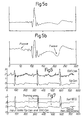
- Fig. 5 shows a) the recordings of the unprocessed signals registered between tip (V) and can and in b) the influence of non-linear amplification which lessens the influence from the local phenomena which one is not interested in this specific application according to the invention.
- This non-linear amplification will lead to smaller details becoming more visible in the signal, i.e. details that have no local character but are describing the total functioning of the heart. In this case the signals have been filtered/transformed or blocked in order to take away the local influence on the signals before the summation of the same.
- the p-wave is emphasized by the non-linear amplification.
- the T-wave is also emphasized in the same manner as is indicated in the figure.
- the non-linear amplification, using a so called transfer function is discussed below.
- Fig. 6 shows the signal registered between the SVC (superior vena cava) and the CAN, and the signals registered between the TIP and the CAN. These signals may e.g. be processed in a neural network, the result of which is shown in Fig. 7, which shows the synthesized signals resulting from above processing.
- the signals in Fig. 6 are used as input signals to a neural network, and compared in practice with a range of a surface ECG (e.g. one heart beat interval) and compared in iterations with the weighted and processed input signals.
- a surface ECG e.g. one heart beat interval
- the parameters of the NN are "frozen” to be used subsequently.
- the surface ECG used in the training of the network is that of the patient in this method, but not necessarily a surface-ECG taken at the same time but one of an earlier date.
- the method can, within the scope of the invention, include IEGMs recordings obtained from paired connected implanted electrodes such as SVC and Can, Tip and Can, RV and Can etc. All signals are according to the method obtained between two poles (groups of interconnected electrodes). Each group is either a single electrode: SVC, RV, Tip, Ring, Can or at least two electrically connected electrodes.
- Fig. 8 shows an enlargement of the diagram in Fig. 7 showing the training area in greater detail.
- the signals may also be added form combinations of interconnected electrodes.
- Fig. 9 shows a) the signal resulting from measuring between unprocessed interconnected electrodes Tip(V) + Can and SVC(Superior Vena Cava) + Can after signal processing in accordance with the invention and below is found a surface ECG.
- a surface ECG One may note the close resemblance between the two signals. This is just one of many possible electrode combinations according to this invention.
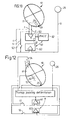
- Fig. 10 shows a first embodiment of the invention comprising an implanted heart stimulator having two electrodes, a ring electrode 22 and a tip electrode 23 implanted in the right ventricle 11 of a heart 10.
- Conductors 1 and 2 from the electrodes 22 and 23, respectively, are connected to the input terminals on a ventricular monitoring unit 32.
- the output signal from the unit 32 will consist of a ventricular IEGM.
- the ventricular IEGM is then used e g for controlling the pacing executed by the active implant 30.
- This part of the active implanted system corresponds to the usual setup for pacing.
- Conductors 4 and 5 connected to the electrodes 23 and 22, respectively are also connected to the input side of an synthesizing unit 60.
- the conductors may be physically (electrically) connected to each other before the input terminal of the unit 60 or they may be processed in the unit 60 as will be discussed later.
- a switch 50 is arranged in one of the conductors 4 or 5 . Connection of the switch 50 and the action of unit 60 can be implemented in a multiplex mode. This is also true in the embodiments below.
- the signals received from the ring electrode 22 and the tip electrode 23 are combined before the synthesizing unit 60 according to the invention.
- the switch 50 may be controlled to either let the signal from the ring electrode 22 pass or not to the synthesizing unit 60.
- the signal measured at the can electrode 26 is also fed to this unit and combined with the signal from 22 and 23 and thus when switch 50 is closed this will provide the synthesized S-ECG according to the invention.
- the reason for adding the signals from the electrodes 22 and 23 is that they will simulate a bigger electrode. This is of course true for all possible electrode combinations forming a group in the sense of this invention.
- a connection between the synthesizing unit 60 and the active implant 30 in the form of a two-headed arrow 93 is shown implying the possibility to control the active implant in accordance with the information received from the synthesized ECG.
- Such an arrow 90 is also shown between the ventricular monitoring unit 32 and the active implant 30 to indicate the existing possibilities for controlling the active implant.
- the arrangement for stimulating the heart from the active implant is not shown explicitly in the drawing. This is well know technique within the art.
- Fig. 10 may of course include other electrodes implanted intra- and/or extracardially and also the combination of signals may be between two electrodes and the CAN as shown or between the CAN and 3 or 4 implanted electrodes, respectively.
- the minimum requirements is the combination of signals from two electrodes, and this does not necessarily include the CAN.
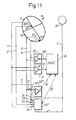
- FIG. 11 Another embodiment of the heart stimulation system including the invention is shown in Fig. 11 in which an active implant having four electrodes, a ring electrode 20 and a tip electrode 21 implanted in the right atrium 11 and a ring electrode 22 and a tip electrode 23 implanted in the right ventricle 12 of a heart 10 .
- the ring electrode 22 and the tip electrode 23 are connected via conductors 3 and 4, respectively, to the input of a ventricular monitoring unit 32.
- a ventricular IEGM may be obtained in the ventricular monitoring unit 32.
- the ring electrode 20 and the tip electrode 21 are connected via conductors 1 and 2 respectively to an atrial monitoring unit 31.
- An atrial IEGM may be obtained in the atrial monitoring unit 31.
- the obtained IEGMs are then used for controlling the pacing executed by the active implant 30, which is indicated in the drawing by two-headed arrows 90, 91.
- This part of the active implant system corresponds to the usual setup for pacing.
- a can electrode 26 which may be the active implant case.
- Fig. 11 shows how to process synthesized or interconnected ECGs in two synthesizing units 60' and 60".
- the intracardiac electrodes 20, 21, 22, 23 are also connected via conductors 1, 2, 3, 4 respectively to the input side of the unit 60'.
- Switches 51, 52, 53, 54 are provided in the conductors 1, 2, 3, 4 in order to connect or disconnect the electrodes 20, 21, 22, 23 to or from the input terminal of the unit 60'.
- To the input side of the same unit 60' the can electrode 26 is connected via conductor 5.
- the can electrode 26 is also connected via conductor 5 to the input terminal of the synthesizing unit 60" as are the two ring electrodes 20 and 22 via conductors 1' and 3', respectively.
- a switch 50 is provided in the conductor 3'.
- the unit 60' is a unit with a more sophisticated form of signal processing.
- a connection in the form of two-headed arrows 92 and 93 between the synthesizing units 60' and 60", respectively, and the active implant 20 are shown so as to indicate the possibility to control the active implant in accordance with the information received from the synthesized ECGs.
- FIG. 12 Yet another embodiment is shown in Fig. 12.
- a defibrillation electrode 24 and in the right ventricle 12 another defibrillation electrode 25 and a tip electrode 23 and the can 26.
- the electrodes are all connected via conductors to the active implant for pacing and defibrillation as is usual.
- the difference from the other embodiments mainly lies in the use of the defibrillation electrodes in the application.
- the active implant in this embodiment can be used for sensing of cardiac events, for pacing in a normal manner and for detection of anomalies in the behaviour of the heart which will necessitate defibrillation.
- the synthesized ECG may in this embodiment, as in the other possible embodiments according to this invention, provide information to be used by the active implant for providing specific actions depending on the behaviour of the heart.
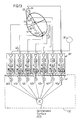
- FIG. 13 there is shown a schematic presentation of a heart 10, having a right atrium 11 and a right ventricle 12.
- a system comprising five intracardiac electrodes is shown implanted in the heart, in the atrium 11 a ring electrode 20, a tip electrode 21 and in the ventricle 12 a ring electrode 22, a tip electrode 23 and a defibrillation electrode 25.
- the system also comprises a patch electrode 27 in contact with the outside of the heart, a defibrillation electrode 24 is placed near where the superior vena cava 13 enters the right atrium, and also the can electrode 26.
- Each of the above electrodes are connected to the input side of a transforming unit 101, resp., and the can electrode 26 is likewise connected to the input side of each one of the transforming units 101 as is indicated by 40. Shown is also a bus 41 connected to the outputs of each one of the units 101. The bus 41 is used for applying individual weights to each output signal 42a...42g in the unit 130 from which an output signal is generated forming a synthesized ECG.
- Fig. 13 Using the system presented schematically in Fig. 13 it is possible to register and/or process signals from two or more electrodes.
- the transforming units 101 in Fig. 13 is shown in greater detail in Fig. 14.
- the intracorporal signals from two or more electrodes, of which one electrode may be the can 26, will be amplified, filtered and possibly blocked during certain time intervals. This may be done by conventional means using well know techniques within the art, such as by using thresholds, or windows restricting either the amplitudes or the frequency of the signals received.
- the blocking of the signals may be individual at predetermined and controllable time intervals, such that the particular signal is prevented from affecting the result at the chosen time intervals. This signal processing will result in pretreated second signals
- These individually processed second signals from two or more electrodes may then be summed together and once more signal processed in a second processing procedure according to the invention, either in the processing unit 130 or by other means.
- the filtering/transforming and blocking circuitry 101 comprising one or more amplifier, filter, block and transfer functions.
- the reason for this first processing is that the intracardiac electrodes will each pick up information as to the electrical activity resulting from cardiac activity in the proximity of the electrode. But they will not only pick up the information activities occurring in the proximity of the electrode but also from activity in other parts of the heart.
- the electrical activity induced in the very near proximity of each electrode will of course give a considerable greater contribution to the signal than activity occurring comparatively farther away.
- the processed signals will then be fed to a second signal processing unit 130 for the summation including the weighting of the individual signals and processed to generate the synthesized surface ECG.
- Electrodes having a large surface and positioned extracardially normally give signals better suited for synthesizing a surface ECG.
- the signals from intracardiac and extracardiac electrodes can be used for mathematical processing by signal processing.
- the signals will thus be processed in order to filter out e.g. high frequency components which mostly are the result of local (in the close proximity) electrical activity. This filtering effect can be accomplished in a more subtle fashion by blocking the signal during a given time period.
- Such a circuit can e.g. be realized by circuitry which detects the fast slope of the IEGM from a bypassing wavefront of electrical activity at an early stage, thereby blocking most of the locally produced signal.
- the result of the signal processing may be even more improved.
- mathematical processing may be done with a slight time delay, which will give time and possibility to remove from the signal, the stored IEGM from the electrode, the part that originates locally, i.e. the contribution from electrical activity in the close proximity of the electrode.
- the part that is removed may then be substituted by interpolation.
- the stored signal will then according to the invention be used instead of the directly obtained signal for the filtering, blocking and multiplication by constants in the second processing procedure with the other intracoporal signals according to the Fig. 13. This is shown in Fig. 17a.
- each signal will be multiplied by a certain constant. This is done in order to favour signals which contain more of far field ECG signals.
- Still another improvement is the exaggerating of low amplitude signals like P-wave in comparison with a QRS-complex. This may be done in the block named "linear and non-linear transfer functions" in Fig. 13 and 14 and Fig. 5b. (conf. discussion in connection with Fig. 5b.) Amplitudes outside specified limits may be clipped or gradually limited by a sigmoidal transfer function.
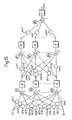
- a neural network has mostly several input signals and one or more output signals. Each input signal is processed and combined with the other weighted input signals. The combination of the signals are further processed in order to produce one or more output signals. The processing of the signals contains multiplication, addition and non-linear signal handling.
- a neural network may have different structures. This structure must first be settled. The neural network then has a number of unknown parameters (weights and biases). Characteristic for the neural network is that it must learn how to adjust these parameters. The learning action is performed on short, but sufficiently long and representative input signal intervals which are fed into the neural network in order to produce an output signal, which will be compared with a reference signal.
- the learning procedure is performed by repeatedly feeding these input signals to the neural network and adjusting each parameter so that finally the output signal from the neural network resembles the reference signal.
- the neural network is now adjusted. New input signals will then produce output signals, which will be similar to the signals that the process, which the neural network is simulating, will produce.
- the input signals are S1, S2, S3 and S4.
- Each input signal is then multiplied by a certain weight (w11 to w4k). For every input signal there is so may weights as there are summing junctions.
- w11 to w4k For every input signal there is so may weights as there are summing junctions.
- k summing junctions In figure 15 all weighted signals and a bias signal are added.
- the bias signal is just a constant voltage.
- the output signal from the summing junctions is then passing a transfer function, denoted " ⁇ ".
- this transfer function is a non-linear function, like the sigmoid function.
- ⁇ a transfer function
- Fig. 16 shows only a single output, Sout.
- the transfer function is denoted " F ". Normally this last transfer function is a linear function.
- Sout is the synthesized surface ECG and the input signals are the intracardiac and/or intrathoracic signals, which contains information about the electrical activity of the heart.
- a similar way to implement this invention is to use Fuzzy Logic instead of a neural network.
- Fuzzy Logic instead of a neural network.
- fuzzy logic Because of this reason software exists that can transform a neural network into an electronic circuit utilizing the Fuzzy Logic technique.
- the invention may be implemented in several ways.
- the signal processing may take place in a device incorporated in the active implant as an integral part of the same or it may take place out of the active implant.
- the active implant may also comprise a transmitter means for transmitting the synthesized ECG via telemetry.
- transmitters mentioned in the description may for reasons of communication by telemetry be a combined transmitter/receiver, or the type of telemetric unit usually provided in active implants.
- Fig. 16 shows the outputs from the implantable electrodes 20,21,22.... and to each electrode the corresponding inputs to a signal processing device 105.
- the signal processing device 105 comprises controllable switching means 160, transforming means 170 in a first unit 101, with one such unit for each input. Each first unit may also comprise e.g. amplification means. Each first unit 101 is also provided with an output 120.
- a second signal processing unit 130 is also shown having inputs 140 and an output 150. Several outputs may of course be provided.
- Connected to the signal processing device 105 is a transmitter 180 for transmitting the signals processed.
- switching means schematically shown at 70 for selectively interconnection of the input signals from one or more electrodes before the signal processing units 101.
- These switches may be connected/disconnected in a multiplexing mode in order to facilitate the process in the active implant, since when short circuiting two or more of the intracardiac electrodes this will affect the pacing/stimulating arrangement in the active implant in which the device according to the invention or part of the device according to the invention is included.
- Fig. 17 is shown another embodiment of the device according to the invention in which there is provided outputs from the implantable electrodes.
- a transmitter 190 for receiving the signals from the electrodes is also arranged. This part of the device is placed in an active implant 50.
- the transmitter 190 is arranged to transmit the signals from the implantable electrodes and two pathways 300 and 301 are shown in order to illustrate two alternative embodiments of the device according to the invention. Actually there need only be one pathway in each embodiment. After the pathway is shown a receiver and in the first alternative Fig. 17a a memory unit 210 for storing of the signals to be processed later is supplied. The memory unit 210 is connectable via a data bus to a processing unit 250. It should be understood in this document that a radio receiver and a radio transmitter are merely examples of a type of receiver and a transmitter. The signals could just as well be transmitted by any method which is well know with in the art.
- the receiver 200 is connected to a signal processing device 250 according to the invention.
- the memory unit for storing may also of course be situated in the active implant.
- the active implant will of course also comprise components usually provided in an active implant such as pacing and /or defibrillation circuitry etc.
Landscapes
- Health & Medical Sciences (AREA)
- Cardiology (AREA)
- Life Sciences & Earth Sciences (AREA)
- Heart & Thoracic Surgery (AREA)
- Animal Behavior & Ethology (AREA)
- General Health & Medical Sciences (AREA)
- Engineering & Computer Science (AREA)
- Biomedical Technology (AREA)
- Veterinary Medicine (AREA)
- Public Health (AREA)
- Radiology & Medical Imaging (AREA)
- Biophysics (AREA)
- Nuclear Medicine, Radiotherapy & Molecular Imaging (AREA)
- Physiology (AREA)
- Physics & Mathematics (AREA)
- Pathology (AREA)
- Medical Informatics (AREA)
- Molecular Biology (AREA)
- Surgery (AREA)
- Electrotherapy Devices (AREA)
- Image Processing (AREA)
- Medical Treatment And Welfare Office Work (AREA)
- Measurement And Recording Of Electrical Phenomena And Electrical Characteristics Of The Living Body (AREA)
Claims (19)
- Extrakorporale Vorrichtung (200, 250) zur Durchführung von Nachfolgebehandlungen bei Patienten mit einem implantierten Herzimpulsgenerator (50),
wobei der genannte implantierte Impulsgenerator eine Vorrichtung zum Abfühlen von IECG-Signalen aufweist, die von dem genannten Herz des Patienten herrühren,
der genannte implantierte Herzimpulsgenerator einen Sender (190) zum Aussenden von IECG-Signalen zu der genannten extrakorporalen Vorrichtung aufweist,
die genannte extrakorporale Vorrichtung einen Telemetrieempfänger (200) zum Empfangen von IECG-Signalen von dem genannten implantierten Impulsgenerator aufweist, wobei die genannte extrakorporale Vorrichtung eine Signalverarbeitungsvorrichtung (250) zum Umwandeln der genannten IECG-Signale in ein synthetisiertes Oberflächen ECG-Signal enthält,
die genannte extrakorporale Vorrichtung Mittel zur Verwendung des genannten äquivalenten synthetisierten Oberflächen ECG- Signals während der genannten Nachfolgebehandlung enthält. - Implantierbarer Herzimpulsgenerator mit einer Vorrichtung (20, 21, 22) zum Abfühlen von aus dem Herzen eines Patienten stammenden IECG-Signalen, wobei der genannte implantierbare Herzimpulsgenerator eine Signalverarbeitungsvorrichtung (250) zum Umwandeln der genannten IECG-Signale in ein synthetisiertes Oberflächen ECG-Signal enthält,
der genannte implantierbare Impulsgenerator ferner einen Sender zum Senden des genannten synthetisierten Oberflächen ECG zu einer extrakorporalen Vorrichtung enthält. - Extrakorporale Vorrichtung nach Anspruch 1 bzw. implantierbarer Impulsgenerator nach Anspruch 2, dadurch gekennzeichnet, dass sie bzw. er eine Signalverarbeitungsvorrichtung mit einer Mehrzahl von ersten individuellen Signalverarbeitungseinheiten (101) enthält, wobei jede erste Einheit (101) einen Eingang (110) für den Empfang eines ersten Eingangssignals aufweist, das sich auf das genannte erste Signal bezieht, welches die intrakorporal abgefühlte Herzaktivität darstellt, und einen Ausgang (120);- eine zweite Signalverarbeitungseinheit (130) mit einer Mehrzahl von Eingängen (140) enthält, wobei jeder Eingang (140) mit einem der genannten Ausgänge (120) der genannten ersten Einheiten gekoppelt ist, die genannte zweite Signalverarbeitungseinheit wenigstens einen Ausgang (150) aufweist;- jede der genannten ersten Signaleinheiten (101) ausgebildet ist, wenigstens ein Eingangssignal jeweils in Übereinstimmung mit wenigstens einer ausgewählten Übertragungsfunktion so zu behandeln, dass sie als Ausgang (120) ein vorbehandeltes Signal erzeugt;- die genannte zweite Signalverarbeitungseinheit (130) ausgebildet ist, wenigstens zwei der genannten vorbehandelten Signale so zu kombinieren, dass wenigstens ein synthetisiertes ECG-Signal (SECG) erzeugt und an dem genannten wenigstens einen Ausgang (150) geliefert wird.
- Signalverarbeitungsvorrichtung nach Anspruch 3, enthaltend eine Vielzahl von Schaltvorrichtung (70) zum selektiven Verbinden vorbestimmter Kombinationen der genannten ersten Eingangssignale.
- Signalverarbeitungsvorrichtung nach einem der Ansprüche 3 bis 4, wobei jede der genannten ersten Einheiten (101) eine steuerbare Schaltvorrichtung (160) zum individuellen Blockieren des betreffenden Eingangssignals während ausgewählter Zeitintervalle enthält.
- Signalverarbeitungsvorrichtung nach einem der Ansprüche 3 bis 5, wobei jede der genannten ersten Einheiten (101) eine Umwandlungseinheit (170) enthält, die genannte Umwandlungseinheit das genannte Eingangssignal in Übereinstimmung mit der genannten wenigstens einen ausgewählten Übertragungsfunktion umwandelt.
- Signalverarbeitungsvorrichtung nach einem der Ansprüche 3 bis 6, wobei die genannte wenigstens eine ausgewählte Übertragungsfunktion aus einer Gruppe ausgewählt ist, die aus einer linearen, einer begrenzten und/oder einer Sigmoidal-Übertragungsfunktion besteht.
- Signalverarbeitungsvorrichtung nach einem der Ansprüche 3 bis 7, wobei die genannten ersten Eingangssignale von wenigstens zwei implantierbaren Elektroden (20, 21, 22, 23, 24, 25, 26, 27) stammen.
- Signalverarbeitungsvorrichtung nach einem der Ansprüche 3 bis 8, wobei die genannte Vorrichtung zum Kombinieren von wenigstens zwei der genannten Signale ein neurales Netzwerk vom assoziativen Komponententyp, eine Fuzzi-Logik und/oder eine Summation ist.
- Signalverarbeitungsvorrichtung nach Anspruch 9, wobei das genannte neurale Netzwerk in einem manuell trainierten Modus arbeitet.
- Signalverarbeitungsvorrichtung nach Anspruch 9, wobei das genannte neurale Netzwerk in einem Selbstlernmodus arbeitet.
- Verfahren zum Synthetisieren wenigstens eines Oberflächen ECG-Signals, mit:- Abfühlen einer Mehrzahl von ersten Signalen von implantierten intra- und extrakardialen Elektroden (20, 21, 22, 23, 24, 25, 26, 27), wobei die genannten ersten Signale zwischen irgendwelchen von zwei der genannten Elektroden gemessen werden, die Informationen enthalten, welche sich auf Ereignisse in enger Nachbarschaft zu den betreffenden Elektroden und auf Ereignissen nicht in der Nachbarschaft beziehen,- Behandeln der genannten Signale durch Blockieren der Signale während ausgewählter Zeitintervalle, die sich auf eine spezielle evozierte oder intrinsische Aktivität im Herzen beziehen,- Erzeugen zweiter Signale durch Verarbeiten der genannten ersten Signale mit wenigstens einer ausgewählten Übertragungsfunktion,- Kombinieren wenigstens zweier Gruppen von Signalen, wobei jede der genannten wenigstens zwei Gruppen wenigstens eines der genannten zweiten Signale enthält, um kombinierte Signale zu erzeugen,- Verarbeiten der genannten wenigstens zwei kombinierten Signale in einer zweiten Verarbeitungsprozedur, um wenigstens ein synthetisiertes Oberflächen ECG-Signal zu erzeugen.
- Verfahren nach Anspruch 12, wobei die genannten ersten und/oder zweiten Signale während ausgewählter Zeitintervalle individuell blockiert werden.
- Verfahren nach Anspruch 12 oder 13, wobei die genannte wenigstens eine ausgewählte Übertragungsfunktion ausgewählt ist aus einer Gruppe bestehend aus einer linearen, einer begrenzten und/oder einer Sigmoidal-Übertragungsfunktion.
- Verfahren nach einem der Ansprüche 12 bis 14, wobei der genannte Summationsprozess die Verarbeitung der kombinierten Signale aus den genannten wenigstens zwei Gruppen von Signalen enthält, von denen jede wenigstens eines der genannten zweiten Signale enthält.
- Verfahren nach einem der Ansprüche 12 bis 15, wobei der Summierungsprozess durch die Operation eines neuralen Netzwerkes des assoziativen Komponententyps und/oder eine Fuzzi-Logik und/oder eine Summation ausgeführt wird.
- Verfahren nach einem der Ansprüche 12 bis 16, wobei ein Oberflächen ECG von einer Person, von der die sich auf die Herzaktivität beziehenden Eingangssignale stammen, als Eingangsbezugssignal in das neurale Netzwerk verwendet wird, während einer oder mehrere Trainingsprozeduren.
- Verfahren nach den Ansprüchen 16 bis 17, wobei das genannte neurale Netzwerk in einem manuell trainierten Modus arbeitet.
- Verfahren nach den Ansprüchen 16 bis 17, wobei das genannte neurale Netzwerk in einem Selbstlernmodus arbeitet.
Applications Claiming Priority (2)
| Application Number | Priority Date | Filing Date | Title |
|---|---|---|---|
| SE9504258 | 1995-11-28 | ||
| SE9504258A SE9504258D0 (sv) | 1995-11-28 | 1995-11-28 | Device and method for generating a synthesized ECG |
Publications (2)
| Publication Number | Publication Date |
|---|---|
| EP0784996A1 EP0784996A1 (de) | 1997-07-23 |
| EP0784996B1 true EP0784996B1 (de) | 2006-11-22 |
Family
ID=20400395
Family Applications (1)
| Application Number | Title | Priority Date | Filing Date |
|---|---|---|---|
| EP96850200A Expired - Lifetime EP0784996B1 (de) | 1995-11-28 | 1996-11-26 | Vorrichtung und Verfahren zur Erzeugung eines synthetisierten Elektrokardiogramms |
Country Status (5)
| Country | Link |
|---|---|
| US (1) | US5740811A (de) |
| EP (1) | EP0784996B1 (de) |
| JP (1) | JPH09215759A (de) |
| DE (1) | DE69636715T2 (de) |
| SE (1) | SE9504258D0 (de) |
Cited By (1)
| Publication number | Priority date | Publication date | Assignee | Title |
|---|---|---|---|---|
| WO2024091557A1 (en) * | 2022-10-28 | 2024-05-02 | Medtronic, Inc. | Atrial sensing without an atrial lead by medical systems |
Families Citing this family (110)
| Publication number | Priority date | Publication date | Assignee | Title |
|---|---|---|---|---|
| US6016446A (en) * | 1998-02-27 | 2000-01-18 | Cardiac Pacemakers, Inc. | Cardiac rhythm management system including nonlinear, non-blanking sense amplifier |
| US6721600B2 (en) * | 2000-01-19 | 2004-04-13 | Medtronic, Inc. | Implantable lead functional status monitor and method |
| US7050851B2 (en) * | 2001-06-29 | 2006-05-23 | Medtronic, Inc. | Implantable cardioverter/defibrillator with housing electrode and lead detection and switching circuitry |
| US6658283B1 (en) | 2001-09-25 | 2003-12-02 | Pacesetter, Inc. | Implantable cardiac stimulation device, system and method which provides an electrogram signal having the appearance of a surface electrocardiogram |
| US7613508B2 (en) * | 2001-09-25 | 2009-11-03 | Pacesetter, Inc. | Implantable cardiac stimulation device, system and method which provides an electrogram signal facilitating measurement of slow-changing electrogram features |
| US6760615B2 (en) | 2001-10-31 | 2004-07-06 | Medtronic, Inc. | Method and apparatus for discriminating between tachyarrhythmias |
| US6865420B1 (en) | 2002-01-14 | 2005-03-08 | Pacesetter, Inc. | Cardiac stimulation device for optimizing cardiac output with myocardial ischemia protection |
| US7280696B2 (en) * | 2002-05-20 | 2007-10-09 | Simmonds Precision Products, Inc. | Video detection/verification system |
| SE0203724D0 (sv) * | 2002-12-16 | 2002-12-16 | St Jude Medical | A cardiac stimulating device |
| US6980850B1 (en) | 2002-12-30 | 2005-12-27 | Pacesetter, Inc. | System and method for emulating a surface EKG using an implantable cardiac stimulation device |
| US6993379B1 (en) | 2002-12-30 | 2006-01-31 | Pacesetter, Inc. | System and method for emulating a surface EKG using an implantable cardiac stimulation device |
| US6813514B1 (en) | 2002-12-30 | 2004-11-02 | Pacesetter, Inc. | System and method for emulating a surface EKG using an implantable cardiac stimulation device |
| SE0300916D0 (sv) * | 2003-03-31 | 2003-03-31 | St Jude Medical | Multi-chamber pacing system |
| SE0300917D0 (sv) * | 2003-03-31 | 2003-03-31 | St Jude Medical | Multi-chamber pacing system |
| US7684861B2 (en) | 2003-11-13 | 2010-03-23 | Cardiac Pacemakers, Inc. | Implantable cardiac monitor upgradeable to pacemaker or cardiac resynchronization device |
| US7546157B1 (en) | 2003-12-12 | 2009-06-09 | Pacesetter, Inc. | System and method for emulating a surface EKG using internal cardiac signals sensed by an implantable medical device |
| US7349732B1 (en) | 2003-12-12 | 2008-03-25 | Pacesetter, Inc. | System and method for emulating a surface EKG using internal cardiac signals sensed by an implantable medical device |
| US7383080B1 (en) | 2003-12-12 | 2008-06-03 | Pacesetter, Inc. | System and method for emulating a surface EKG using internal cardiac signals sensed by an implantable medical device |
| US7933643B1 (en) | 2003-12-12 | 2011-04-26 | Pacesetter, Inc. | System and method for displaying an emulated surface EKG using an external programming device |
| US7945314B1 (en) | 2003-12-12 | 2011-05-17 | Pacesetter, Inc. | System and method for emulating a surface EKG for use with transtelephonic monitoring of an implantable medical device |
| US7299086B2 (en) | 2004-03-05 | 2007-11-20 | Cardiac Pacemakers, Inc. | Wireless ECG in implantable devices |
| US7751890B2 (en) | 2004-07-14 | 2010-07-06 | Cardiac Pacemakers, Inc. | Self-diagnostic method and system for implantable cardiac device |
| US7212849B2 (en) | 2004-10-28 | 2007-05-01 | Cardiac Pacemakers, Inc. | Methods and apparatuses for arrhythmia detection and classification using wireless ECG |
| US8730031B2 (en) | 2005-04-28 | 2014-05-20 | Proteus Digital Health, Inc. | Communication system using an implantable device |
| US8802183B2 (en) | 2005-04-28 | 2014-08-12 | Proteus Digital Health, Inc. | Communication system with enhanced partial power source and method of manufacturing same |
| CN102379684B (zh) | 2005-04-28 | 2014-11-19 | 普罗透斯数字保健公司 | 药物信息系统 |
| US9198608B2 (en) | 2005-04-28 | 2015-12-01 | Proteus Digital Health, Inc. | Communication system incorporated in a container |
| US8912908B2 (en) | 2005-04-28 | 2014-12-16 | Proteus Digital Health, Inc. | Communication system with remote activation |
| US8836513B2 (en) | 2006-04-28 | 2014-09-16 | Proteus Digital Health, Inc. | Communication system incorporated in an ingestible product |
| EP1920418A4 (de) | 2005-09-01 | 2010-12-29 | Proteus Biomedical Inc | Implantierbare drahtlose kommunikationssysteme |
| EP2471450A1 (de) | 2005-10-14 | 2012-07-04 | Nanostim, Inc. | Leitungsloser Herzschrittmacher und System |
| US9168383B2 (en) | 2005-10-14 | 2015-10-27 | Pacesetter, Inc. | Leadless cardiac pacemaker with conducted communication |
| CA2650920C (en) | 2006-05-02 | 2016-10-18 | Proteus Biomedical, Inc. | Patient customized therapeutic regimens |
| US8000780B2 (en) | 2006-06-27 | 2011-08-16 | Cardiac Pacemakers, Inc. | Detection of myocardial ischemia from the time sequence of implanted sensor measurements |
| ATE444778T1 (de) * | 2006-09-07 | 2009-10-15 | Biotronik Crm Patent Ag | Zusammengesetztes fernfeld-elektrokardiogramm |
| FR2906123A1 (fr) * | 2006-09-25 | 2008-03-28 | Ela Medical Soc Par Actions Si | Procede de reconstruction d'un electrocardiogramme de surface a partir d'un electrogramme endocavitaire |
| US8054140B2 (en) | 2006-10-17 | 2011-11-08 | Proteus Biomedical, Inc. | Low voltage oscillator for medical devices |
| MY158019A (en) | 2006-10-25 | 2016-08-30 | Proteus Digital Health Inc | Controlled activation ingestible identifier |
| DE102006054474A1 (de) * | 2006-11-18 | 2008-05-21 | Biotronik Crm Patent Ag | Verfahren zur Erfassung des Myokardzustandes des Herzens sowie eine Messeinrichtung zur Durchführung dieses Verfahrens |
| US8718193B2 (en) | 2006-11-20 | 2014-05-06 | Proteus Digital Health, Inc. | Active signal processing personal health signal receivers |
| US8175709B2 (en) * | 2007-01-30 | 2012-05-08 | Biotronik Crm Patent Ag | Heart monitoring system and method |
| PT3785599T (pt) | 2007-02-01 | 2022-10-21 | Otsuka Pharma Co Ltd | Sistemas de marcadores de eventos ingeríveis |
| CA2676280C (en) | 2007-02-14 | 2018-05-22 | Proteus Biomedical, Inc. | In-body power source having high surface area electrode |
| US9270025B2 (en) | 2007-03-09 | 2016-02-23 | Proteus Digital Health, Inc. | In-body device having deployable antenna |
| WO2008112577A1 (en) | 2007-03-09 | 2008-09-18 | Proteus Biomedical, Inc. | In-body device having a multi-directional transmitter |
| US8115618B2 (en) | 2007-05-24 | 2012-02-14 | Proteus Biomedical, Inc. | RFID antenna for in-body device |
| DK2192946T3 (da) | 2007-09-25 | 2022-11-21 | Otsuka Pharma Co Ltd | Kropsintern anordning med virtuel dipol signalforstærkning |
| US8116859B2 (en) | 2007-10-24 | 2012-02-14 | Ela Medical S.A.S. | Electrocardiologic device for the assisted diagnosis of brugada syndrome or early repolarization syndrome |
| WO2009081343A1 (en) * | 2007-12-20 | 2009-07-02 | Koninklijke Philips Electronics N.V. | Electrode diversity for body-coupled communication systems |
| US8258962B2 (en) | 2008-03-05 | 2012-09-04 | Proteus Biomedical, Inc. | Multi-mode communication ingestible event markers and systems, and methods of using the same |
| CA3039236C (en) | 2008-07-08 | 2022-05-17 | Proteus Digital Health, Inc. | Ingestible event marker data framework |
| CN104382598A (zh) | 2008-08-13 | 2015-03-04 | 普罗透斯数字保健公司 | 一种产生识别器的方法 |
| KR101192690B1 (ko) | 2008-11-13 | 2012-10-19 | 프로테우스 디지털 헬스, 인코포레이티드 | 섭취 가능한 치료 활성화 시스템, 치료 장치 및 방법 |
| US8055334B2 (en) | 2008-12-11 | 2011-11-08 | Proteus Biomedical, Inc. | Evaluation of gastrointestinal function using portable electroviscerography systems and methods of using the same |
| US9659423B2 (en) | 2008-12-15 | 2017-05-23 | Proteus Digital Health, Inc. | Personal authentication apparatus system and method |
| US9439566B2 (en) | 2008-12-15 | 2016-09-13 | Proteus Digital Health, Inc. | Re-wearable wireless device |
| TWI424832B (zh) | 2008-12-15 | 2014-02-01 | 波提亞斯數位康健公司 | 與身體有關的接收器及其方法 |
| EP3395333A1 (de) | 2009-01-06 | 2018-10-31 | Proteus Digital Health, Inc. | System zur dosierten verabreichung von arzneimitteln |
| SG172846A1 (en) | 2009-01-06 | 2011-08-29 | Proteus Biomedical Inc | Ingestion-related biofeedback and personalized medical therapy method and system |
| US8527068B2 (en) | 2009-02-02 | 2013-09-03 | Nanostim, Inc. | Leadless cardiac pacemaker with secondary fixation capability |
| EP2233069B1 (de) | 2009-03-25 | 2013-04-24 | Sorin CRM SAS | Aktive medizinische Vorrichtung, die nicht-lineare Filtermittel zur Rekonstruktion eines Oberflächenelektrokardiogramms aus einer endokavitären Aktionsstromkurve umfasst |
| WO2010111403A2 (en) | 2009-03-25 | 2010-09-30 | Proteus Biomedical, Inc. | Probablistic pharmacokinetic and pharmacodynamic modeling |
| EP2238897B1 (de) | 2009-04-06 | 2011-04-13 | Sorin CRM SAS | Aktive medizinische Vorrichtung, die Mittel zur Rekonstruktion eines Oberflächenelektrokardiogramms auf der Grundlage einer endokavitären Aktionsstromkurve umfasst |
| EP2238896B1 (de) * | 2009-04-06 | 2011-06-22 | Sorin CRM SAS | Aktive medizinische Vorrichtung, die Mittel zur Rekonstruktion eines Oberflächenelektrokardiogramms auf der Grundlage von Fernfeldsignalen aus einer endokavitären Aktionsstromkurve umfasst |
| NZ596292A (en) | 2009-04-28 | 2014-04-30 | Proteus Digital Health Inc | Highly reliable ingestible event markers and methods for using the same |
| US9149423B2 (en) | 2009-05-12 | 2015-10-06 | Proteus Digital Health, Inc. | Ingestible event markers comprising an ingestible component |
| WO2011022732A2 (en) | 2009-08-21 | 2011-02-24 | Proteus Biomedical, Inc. | Apparatus and method for measuring biochemical parameters |
| TWI517050B (zh) | 2009-11-04 | 2016-01-11 | 普羅托斯數位健康公司 | 供應鏈管理之系統 |
| UA109424C2 (uk) | 2009-12-02 | 2015-08-25 | Фармацевтичний продукт, фармацевтична таблетка з електронним маркером і спосіб виготовлення фармацевтичної таблетки | |
| BR112012019212A2 (pt) | 2010-02-01 | 2017-06-13 | Proteus Digital Health Inc | sistema de coleta de dados |
| EP2555737A4 (de) | 2010-04-07 | 2013-09-18 | Proteus Digital Health Inc | Verzehrbare miniaturvorrichtung |
| TWI557672B (zh) | 2010-05-19 | 2016-11-11 | 波提亞斯數位康健公司 | 用於從製造商跟蹤藥物直到患者之電腦系統及電腦實施之方法、用於確認將藥物給予患者的設備及方法、患者介面裝置 |
| WO2012051237A1 (en) | 2010-10-12 | 2012-04-19 | Nanostim, Inc. | Temperature sensor for a leadless cardiac pacemaker |
| US9060692B2 (en) | 2010-10-12 | 2015-06-23 | Pacesetter, Inc. | Temperature sensor for a leadless cardiac pacemaker |
| CN103249454A (zh) | 2010-10-13 | 2013-08-14 | 内诺斯蒂姆股份有限公司 | 带有防旋出构造的无引线心脏起搏器 |
| JP2014504902A (ja) | 2010-11-22 | 2014-02-27 | プロテウス デジタル ヘルス, インコーポレイテッド | 医薬品を有する摂取可能なデバイス |
| EP2651502B1 (de) | 2010-12-13 | 2016-11-09 | Pacesetter, Inc. | Herzschrittmacher-rückholsysteme |
| EP2651494B1 (de) | 2010-12-13 | 2017-02-15 | Pacesetter, Inc. | Implantationskatheter |
| WO2012088118A1 (en) | 2010-12-20 | 2012-06-28 | Nanostim, Inc. | Leadless pacemaker with radial fixation mechanism |
| KR101843083B1 (ko) * | 2011-01-26 | 2018-03-29 | 삼성전자주식회사 | 다중의 단위 측정기들을 포함하는 생체 신호 측정 장치 및 방법 |
| WO2012125425A2 (en) | 2011-03-11 | 2012-09-20 | Proteus Biomedical, Inc. | Wearable personal body associated device with various physical configurations |
| WO2015112603A1 (en) | 2014-01-21 | 2015-07-30 | Proteus Digital Health, Inc. | Masticable ingestible product and communication system therefor |
| US9756874B2 (en) | 2011-07-11 | 2017-09-12 | Proteus Digital Health, Inc. | Masticable ingestible product and communication system therefor |
| US8923957B2 (en) * | 2011-07-15 | 2014-12-30 | Verathon Inc. | Data conversion in ECG techniques |
| CA2842952C (en) | 2011-07-21 | 2019-01-08 | Proteus Digital Health, Inc. | Mobile communication device, system, and method |
| US9511236B2 (en) | 2011-11-04 | 2016-12-06 | Pacesetter, Inc. | Leadless cardiac pacemaker with integral battery and redundant welds |
| US9235683B2 (en) | 2011-11-09 | 2016-01-12 | Proteus Digital Health, Inc. | Apparatus, system, and method for managing adherence to a regimen |
| AU2013293234B2 (en) | 2012-07-23 | 2017-08-31 | Otsuka Pharmaceutical Co., Ltd. | Techniques for manufacturing ingestible event markers comprising an ingestible component |
| EP2879758B1 (de) | 2012-08-01 | 2018-04-18 | Pacesetter, Inc. | Biostimulatorschaltung mit fliegender zelle |
| DK2910013T3 (en) | 2012-10-18 | 2018-08-06 | Proteus Digital Health Inc | Apparatus, system and method for adaptive optimization for power output and transmit power in a power source for a communication device |
| WO2014120669A1 (en) | 2013-01-29 | 2014-08-07 | Proteus Digital Health, Inc. | Highly-swellable polymeric films and compositions comprising the same |
| US10175376B2 (en) | 2013-03-15 | 2019-01-08 | Proteus Digital Health, Inc. | Metal detector apparatus, system, and method |
| WO2014151929A1 (en) | 2013-03-15 | 2014-09-25 | Proteus Digital Health, Inc. | Personal authentication apparatus system and method |
| JP6511439B2 (ja) | 2013-06-04 | 2019-05-15 | プロテウス デジタル ヘルス, インコーポレイテッド | データ収集および転帰の査定のためのシステム、装置、および方法 |
| US9796576B2 (en) | 2013-08-30 | 2017-10-24 | Proteus Digital Health, Inc. | Container with electronically controlled interlock |
| CA2924815C (en) | 2013-09-20 | 2017-06-20 | Proteus Digital Health, Inc. | Methods, devices and systems for receiving and decoding a signal in the presence of noise using slices and warping |
| JP2016537924A (ja) | 2013-09-24 | 2016-12-01 | プロテウス デジタル ヘルス, インコーポレイテッド | 事前に正確に把握されていない周波数において受信された電磁信号に関する使用のための方法および装置 |
| US10084880B2 (en) | 2013-11-04 | 2018-09-25 | Proteus Digital Health, Inc. | Social media networking based on physiologic information |
| US10449361B2 (en) | 2014-01-10 | 2019-10-22 | Cardiac Pacemakers, Inc. | Systems and methods for treating cardiac arrhythmias |
| US9592391B2 (en) | 2014-01-10 | 2017-03-14 | Cardiac Pacemakers, Inc. | Systems and methods for detecting cardiac arrhythmias |
| US10463866B2 (en) | 2014-07-11 | 2019-11-05 | Cardiac Pacemakers, Inc. | Systems and methods for treating cardiac arrhythmias |
| US9669230B2 (en) | 2015-02-06 | 2017-06-06 | Cardiac Pacemakers, Inc. | Systems and methods for treating cardiac arrhythmias |
| US11051543B2 (en) | 2015-07-21 | 2021-07-06 | Otsuka Pharmaceutical Co. Ltd. | Alginate on adhesive bilayer laminate film |
| US10299688B2 (en) * | 2015-10-23 | 2019-05-28 | Cardiac Pacemakers, Inc. | Multi-vector sensing in cardiac devices with signal combinations |
| MX2019000888A (es) | 2016-07-22 | 2019-06-03 | Proteus Digital Health Inc | Percepcion y deteccion electromagnetica de marcadores de evento ingeribles. |
| US10758737B2 (en) | 2016-09-21 | 2020-09-01 | Cardiac Pacemakers, Inc. | Using sensor data from an intracardially implanted medical device to influence operation of an extracardially implantable cardioverter |
| TWI735689B (zh) | 2016-10-26 | 2021-08-11 | 日商大塚製藥股份有限公司 | 製造含有可攝食性事件標記之膠囊之方法 |
| SE541874C2 (en) * | 2017-04-04 | 2020-01-02 | Coala Life Ab | Capturing ecg measurements in a portable sensor device |
| EP3476288B1 (de) | 2017-10-31 | 2025-04-30 | Nokia Technologies Oy | Verfahren, vorrichtung und computerprogramm zum synchronisieren von biopotentialsignalen |
| CN111419213A (zh) * | 2020-03-11 | 2020-07-17 | 哈尔滨工业大学 | 一种基于深度学习的ecg心电信号生成方法 |
Family Cites Families (13)
| Publication number | Priority date | Publication date | Assignee | Title |
|---|---|---|---|---|
| US4870974A (en) | 1987-09-30 | 1989-10-03 | Chinese Pla General Hospital | Apparatus and method for detecting heart characteristics by way of electrical stimulation |
| US5058581A (en) * | 1990-02-20 | 1991-10-22 | Siemens-Pacesetter, Inc. | Telemetry apparatus and method for implantable tissue stimulator |
| JPH04279175A (ja) * | 1990-07-03 | 1992-10-05 | Telectronics Nv | 不整脈制御装置および不整脈検出方法 |
| US5058598A (en) * | 1990-08-03 | 1991-10-22 | Nicklas John M | Method and apparatus for synthesizing leads of an electrocardiogram |
| AU645848B2 (en) * | 1991-01-15 | 1994-01-27 | Pacesetter Ab | A system and method for post-processing intracardiac signals |
| WO1992017240A1 (en) * | 1991-04-05 | 1992-10-15 | Medtronic, Inc. | Subcutaneous multi-electrode sensing system |
| US5313953A (en) * | 1992-01-14 | 1994-05-24 | Incontrol, Inc. | Implantable cardiac patient monitor |
| US5231990A (en) * | 1992-07-09 | 1993-08-03 | Spacelabs, Medical, Inc. | Application specific integrated circuit for physiological monitoring |
| SE9203284D0 (sv) * | 1992-11-04 | 1992-11-04 | Siemens Elema Ab | Hjaertstimulator |
| US5330512A (en) * | 1992-12-28 | 1994-07-19 | Cardiac Pacemakers, Inc. | Electrode charge-neutral sensing of evoked ECG |
| DE4307545A1 (de) * | 1993-03-10 | 1994-09-15 | Siemens Ag | Gerät und Verfahren zur Bestimmung des Ortes und/oder der Ausdehnung von Ischämien und/oder Infarkten im Herzen eines Lebewesens |
| DE4310412C1 (de) * | 1993-03-31 | 1994-07-21 | Manfred Dr Zehender | Vorrichtung zur Signalanalyse des elektrischen Potentialverlaufes der Herzerregung |
| US5404877A (en) * | 1993-06-04 | 1995-04-11 | Telectronics Pacing Systems, Inc. | Leadless implantable sensor assembly and a cardiac emergency warning alarm |
-
1995
- 1995-11-28 SE SE9504258A patent/SE9504258D0/xx unknown
-
1996
- 1996-11-26 DE DE69636715T patent/DE69636715T2/de not_active Expired - Lifetime
- 1996-11-26 EP EP96850200A patent/EP0784996B1/de not_active Expired - Lifetime
- 1996-11-26 US US08/756,374 patent/US5740811A/en not_active Expired - Lifetime
- 1996-11-28 JP JP31797096A patent/JPH09215759A/ja active Pending
Cited By (1)
| Publication number | Priority date | Publication date | Assignee | Title |
|---|---|---|---|---|
| WO2024091557A1 (en) * | 2022-10-28 | 2024-05-02 | Medtronic, Inc. | Atrial sensing without an atrial lead by medical systems |
Also Published As
| Publication number | Publication date |
|---|---|
| US5740811A (en) | 1998-04-21 |
| JPH09215759A (ja) | 1997-08-19 |
| EP0784996A1 (de) | 1997-07-23 |
| DE69636715T2 (de) | 2007-09-20 |
| SE9504258D0 (sv) | 1995-11-28 |
| DE69636715D1 (de) | 2007-01-04 |
Similar Documents
| Publication | Publication Date | Title |
|---|---|---|
| US5740811A (en) | Device and method for generating a synthesized ECG | |
| EP1897587B1 (de) | Zusammengesetztes Fernfeld-Elektrokardiogramm | |
| JP5371190B2 (ja) | 埋込可能な心臓デバイスによる電位図の形態準拠診断的監視 | |
| US4799486A (en) | Refractoriless atrial sensing in dual chamber pacemakers | |
| US5018523A (en) | Apparatus for common mode stimulation with bipolar sensing | |
| US7277754B2 (en) | Method and system for removing pacing artifacts from subcutaneous electrocardiograms | |
| US5324310A (en) | Cardiac pacemaker with auto-capture function | |
| US5265601A (en) | Dual chamber cardiac pacing from a single electrode | |
| US6275734B1 (en) | Efficient generation of sensing signals in an implantable medical device such as a pacemaker or ICD | |
| JP2655204B2 (ja) | 植え込み型の医療用装置 | |
| US8781580B2 (en) | Pacing sequence optimization | |
| US8175709B2 (en) | Heart monitoring system and method | |
| Barold et al. | Cardiac pacemakers and resynchronization step by step: An illustrated guide | |
| US7792585B1 (en) | Expedited set-up of multi-electrode lead (MEL) | |
| US9681815B2 (en) | Reconstruction of a surface electrocardiogram from an endocardial electrogram using non-linear filtering | |
| US7330761B2 (en) | Baseline adaptation for cardiac pacing response classification | |
| JP2001520544A (ja) | 埋込可能な医療用心臓刺激器具における動的帯域幅制御方法 | |
| DE60208286T2 (de) | Mehrkammer Herzschrittmacher mit automatischer Fangverifikation zur Reduzierung von echten und durch die Austastzeit induzierten Nichterfassungen, und entsprechendes Verfahren | |
| US8781581B2 (en) | System and method for determining the origin of a sensed beat | |
| US5709213A (en) | Low noise, high bandwidth, augmented lead circuit for acquisition of cardiac pacing artifacts | |
| WO2007038588A1 (en) | Telemetry of combined endocavitary atrial and ventricular signals | |
| US20060129193A1 (en) | Template initialization for evoked response detection | |
| US6947794B1 (en) | System and method with improved automatic testing functions for defining capture thresholds | |
| CN108778112A (zh) | 检测刺激脉冲 | |
| LAU et al. | Initial clinical experience with a single pass VDDR pacing system |
Legal Events
| Date | Code | Title | Description |
|---|---|---|---|
| PUAI | Public reference made under article 153(3) epc to a published international application that has entered the european phase |
Free format text: ORIGINAL CODE: 0009012 |
|
| AK | Designated contracting states |
Kind code of ref document: A1 Designated state(s): DE ES FR GB IT NL |
|
| 17P | Request for examination filed |
Effective date: 19980131 |
|
| RAP1 | Party data changed (applicant data changed or rights of an application transferred) |
Owner name: ST. JUDE MEDICAL AB |
|
| 17Q | First examination report despatched |
Effective date: 20040304 |
|
| GRAP | Despatch of communication of intention to grant a patent |
Free format text: ORIGINAL CODE: EPIDOSNIGR1 |
|
| GRAS | Grant fee paid |
Free format text: ORIGINAL CODE: EPIDOSNIGR3 |
|
| GRAA | (expected) grant |
Free format text: ORIGINAL CODE: 0009210 |
|
| AK | Designated contracting states |
Kind code of ref document: B1 Designated state(s): DE ES FR GB IT NL |
|
| PG25 | Lapsed in a contracting state [announced via postgrant information from national office to epo] |
Ref country code: NL Free format text: LAPSE BECAUSE OF FAILURE TO SUBMIT A TRANSLATION OF THE DESCRIPTION OR TO PAY THE FEE WITHIN THE PRESCRIBED TIME-LIMIT Effective date: 20061122 Ref country code: IT Free format text: LAPSE BECAUSE OF FAILURE TO SUBMIT A TRANSLATION OF THE DESCRIPTION OR TO PAY THE FEE WITHIN THE PRESCRIBED TIME-LIMIT;WARNING: LAPSES OF ITALIAN PATENTS WITH EFFECTIVE DATE BEFORE 2007 MAY HAVE OCCURRED AT ANY TIME BEFORE 2007. THE CORRECT EFFECTIVE DATE MAY BE DIFFERENT FROM THE ONE RECORDED. Effective date: 20061122 |
|
| REG | Reference to a national code |
Ref country code: GB Ref legal event code: FG4D |
|
| REF | Corresponds to: |
Ref document number: 69636715 Country of ref document: DE Date of ref document: 20070104 Kind code of ref document: P |
|
| PG25 | Lapsed in a contracting state [announced via postgrant information from national office to epo] |
Ref country code: ES Free format text: LAPSE BECAUSE OF FAILURE TO SUBMIT A TRANSLATION OF THE DESCRIPTION OR TO PAY THE FEE WITHIN THE PRESCRIBED TIME-LIMIT Effective date: 20070305 |
|
| NLV1 | Nl: lapsed or annulled due to failure to fulfill the requirements of art. 29p and 29m of the patents act | ||
| EN | Fr: translation not filed | ||
| PLBE | No opposition filed within time limit |
Free format text: ORIGINAL CODE: 0009261 |
|
| STAA | Information on the status of an ep patent application or granted ep patent |
Free format text: STATUS: NO OPPOSITION FILED WITHIN TIME LIMIT |
|
| 26N | No opposition filed |
Effective date: 20070823 |
|
| PG25 | Lapsed in a contracting state [announced via postgrant information from national office to epo] |
Ref country code: FR Free format text: LAPSE BECAUSE OF FAILURE TO SUBMIT A TRANSLATION OF THE DESCRIPTION OR TO PAY THE FEE WITHIN THE PRESCRIBED TIME-LIMIT Effective date: 20070713 |
|
| PG25 | Lapsed in a contracting state [announced via postgrant information from national office to epo] |
Ref country code: FR Free format text: LAPSE BECAUSE OF FAILURE TO SUBMIT A TRANSLATION OF THE DESCRIPTION OR TO PAY THE FEE WITHIN THE PRESCRIBED TIME-LIMIT Effective date: 20061122 |
|
| PGFP | Annual fee paid to national office [announced via postgrant information from national office to epo] |
Ref country code: GB Payment date: 20101130 Year of fee payment: 15 |
|
| PGFP | Annual fee paid to national office [announced via postgrant information from national office to epo] |
Ref country code: DE Payment date: 20121128 Year of fee payment: 17 |
|
| GBPC | Gb: european patent ceased through non-payment of renewal fee |
Effective date: 20121126 |
|
| PG25 | Lapsed in a contracting state [announced via postgrant information from national office to epo] |
Ref country code: GB Free format text: LAPSE BECAUSE OF NON-PAYMENT OF DUE FEES Effective date: 20121126 |
|
| PG25 | Lapsed in a contracting state [announced via postgrant information from national office to epo] |
Ref country code: DE Free format text: LAPSE BECAUSE OF NON-PAYMENT OF DUE FEES Effective date: 20140603 |
|
| REG | Reference to a national code |
Ref country code: DE Ref legal event code: R119 Ref document number: 69636715 Country of ref document: DE Effective date: 20140603 |