EP0784008A2 - Véhicule propulsé par force musculaire - Google Patents
Véhicule propulsé par force musculaire Download PDFInfo
- Publication number
- EP0784008A2 EP0784008A2 EP97100363A EP97100363A EP0784008A2 EP 0784008 A2 EP0784008 A2 EP 0784008A2 EP 97100363 A EP97100363 A EP 97100363A EP 97100363 A EP97100363 A EP 97100363A EP 0784008 A2 EP0784008 A2 EP 0784008A2
- Authority
- EP
- European Patent Office
- Prior art keywords
- generator
- electric motor
- vehicle according
- vehicle
- speed
- Prior art date
- Legal status (The legal status is an assumption and is not a legal conclusion. Google has not performed a legal analysis and makes no representation as to the accuracy of the status listed.)
- Granted
Links
Images

Classifications
-
- B—PERFORMING OPERATIONS; TRANSPORTING
- B62—LAND VEHICLES FOR TRAVELLING OTHERWISE THAN ON RAILS
- B62M—RIDER PROPULSION OF WHEELED VEHICLES OR SLEDGES; POWERED PROPULSION OF SLEDGES OR SINGLE-TRACK CYCLES; TRANSMISSIONS SPECIALLY ADAPTED FOR SUCH VEHICLES
- B62M6/00—Rider propulsion of wheeled vehicles with additional source of power, e.g. combustion engine or electric motor
- B62M6/40—Rider propelled cycles with auxiliary electric motor
- B62M6/60—Rider propelled cycles with auxiliary electric motor power-driven at axle parts
-
- B—PERFORMING OPERATIONS; TRANSPORTING
- B62—LAND VEHICLES FOR TRAVELLING OTHERWISE THAN ON RAILS
- B62M—RIDER PROPULSION OF WHEELED VEHICLES OR SLEDGES; POWERED PROPULSION OF SLEDGES OR SINGLE-TRACK CYCLES; TRANSMISSIONS SPECIALLY ADAPTED FOR SUCH VEHICLES
- B62M6/00—Rider propulsion of wheeled vehicles with additional source of power, e.g. combustion engine or electric motor
- B62M6/40—Rider propelled cycles with auxiliary electric motor
- B62M6/60—Rider propelled cycles with auxiliary electric motor power-driven at axle parts
- B62M6/65—Rider propelled cycles with auxiliary electric motor power-driven at axle parts with axle and driving shaft arranged coaxially
Definitions
- Previous vehicles that can be operated with muscle power are usually provided with a device for mechanical power transmission between the location of the application of power with muscle power, for example a pedal crank with pedals, and the location of the power conversion into motion drive, for example a driven vehicle wheel.
- this device for mechanical power transmission is equipped with a switching device in order to be able to choose from several gear ratios or gear ratios.
- the vehicle according to the invention in particular the bicycle, is constructed according to the fundamentally different principle of transmitting the power from the place where the power is applied to the place where the power is consumed, not by mechanical means but by electrical means.
- This results in considerably more favorable conditions for the "translation” or “reduction” between the place where the service is performed and the place where the service is implemented in the motion drive, and for any changes to this "translation” or "reduction”.
- Generators and electric motors are components that can be easily built as components with very high efficiency; they can be mass-produced inexpensively and require practically no maintenance. Both the generator and the electric motor can be designed in a linear design or in a rotary design. For the sake of simplicity, the following description of the invention and a relevant part of the claims are aimed at the rotary construction. However, it is expressly pointed out that the scope of the invention also includes the linear design. Terms such as torque or speed are therefore to be understood as “torque or linear force" and “speed or linear speed”. Nonetheless, the rotary construction of the generator and / or electric motor is preferred, because it is normally easier to implement in practice.
- Generators of the usual types normally supply alternating current, unless they are converted into direct current by suitable components, in the simple case, for example, a mechanical commutator becomes.
- a passive, uncontrolled rectifier to the generator. This rectifier can feed a DC voltage intermediate circuit, from which the drive electric motor can be fed in a controllable manner.
- a generator with a controlled decoupling of electrical power is provided as the generator, particularly preferably in the form of electronic commutation.
- a typical example of this is the use of a power electronic four-quadrant inverter based on IGBT semiconductor components.
- the current profile in the coils of the generator can be actively influenced in the sense of an approximation to the voltage profile.
- Another possibility is to assign a controlled rectifier to the generator. Again, what was said in the previous paragraph applies to the DC link and the supply of the electric motor.
- a particularly noteworthy advantage of the controlled decoupling of electrical power is that this decoupling can be varied in a technically simple manner.
- the size of the electrical power generated - apart from the normally minor electrical losses - is the product of the torque and generator speed applied to the generator.
- the vehicle user can change the amount of electrical power by varying the generator speed.
- the generator speed In the case of passive, uncontrolled rectifier changes with the generator speed, the generator torque according to the generator characteristic and the electrical boundary conditions.
- the torque required to drive the generator (but also the generator speed) can be changed either by the programmed control system or by the vehicle user, in order in this way to influence the electrical power generated.
- An increased electrical power from the generator should normally be converted into increased drive power on the vehicle by means of the electric motor.
- the increased electrical power is first of all converted into increased torque of the electric motor (because the speed of the electric motor and, coupled therewith, the driving speed of the vehicle are practically not suddenly increased can).
- the increased torque of the electric motor causes the vehicle to accelerate (provided that the driving resistance does not increase precisely in this time phase, for example due to a mountain climb to be mastered). Since the driving resistance normally increases with increasing driving speed, in particular due to the increasing air resistance, the vehicle movement moves to a new state of equilibrium, in which the electric motor converts the increased electrical power partly through increased electric motor torque M2 and partly through increased electric motor speed n2.
- a very similar transition to a new state of equilibrium occurs if the size of the electrical power generated does not increase, but the driving resistance decreases, for example when driving downhill or when the tailwind begins; the vehicle increases its driving speed until the new equilibrium is reached.
- the transition to a new equilibrium of vehicle movement takes place in a completely analogous manner, but in the opposite direction, as it were, when the amount of electrical power generated decreases or driving resistance increases, for example when driving uphill; the vehicle's new equilibrium driving speed is lower than before.
- the vehicle user has an operating device for gradually or continuously changing the size of the output electrical power, which is connected to the electronic control of the generator.
- the "pedaling sensation” shows an increase in the output electrical power as "it is now more difficult to pedal", i.e. by an increased torque to be provided, conversely, when the decoupled electrical power is reduced; this is similar to the change in pedaling when shifting up or down with a conventional bicycle.
- the fixed transmission ratio between pedal crank and wheel known from conventional shifting devices in bicycles is simulated electronically.
- the torque delivered by the electric motor is determined via the quotient of power (possibly taking into account the efficiency) and speed (or angular velocity) or via the torque delivered by the electronic control to the coils of the electric motor
- Electric motor determined in approximately linear current level (whereby the current is determined from the current specification or is measured directly) and thus the torque to be absorbed by the generator is determined via the amount of current in the generator coils by appropriate setting of the electronic control.
- a desired ratio is set between the two torques, that of the motor and that of the generator, either switchable in steps or continuously.
- the torque of the generator which the vehicle user has to provide, depends on the level of the torque generated by the electric motor and thus applied to the wheel.
- the gear ratios are determined by the vehicle user in the case of step switchability e.g. by a switch based on the conventional gear lever or in the case of infinitely variable adjustment e.g. selectable by an electrical potentiometer.
- the specified design also includes the possibility of the freewheel function of conventional bicycles, i.e. Driving force and power is only transmitted when the vehicle user drives at the speed specified by the drive wheel.
- Adjusting the decoupled electrical power at the will of the vehicle user is not the only option. Rather, in a further embodiment of the invention, a vehicle design is preferred in which the electronic control automatically changes the size of the decoupled electrical power or the torque ratio mentioned when the torque applied to the generator or the speed of the generator leaves a predetermined range.
- This predetermined range is preferably set so that the vehicle user drives the generator in a range of comfortable driving speed. If the vehicle user, in the desire for higher power generation, comes out of this comfortable drive speed range, it makes more sense to a higher torque to be applied to the generator (so it would be better to pedal harder) and vice versa when coming out of the comfortable speed range downwards. The same applies if you instead consider a range of torque that can be comfortably managed on the generator.
- said predetermined range can be changed, e.g. can be expanded, narrowed, moved up or moved down at the request of the vehicle user. Different vehicle users will find different predetermined areas comfortable.
- the personal physical training status, the ambient temperature, the prevailing air humidity or simply the mood of the day may also be parameters that make the vehicle user concerned think that changing the predetermined range is favorable.
- Generators have a torque-speed characteristic, which is normally not a horizontal curve of the torque over the speed and not a proportional characteristic. Specifically, the characteristics depend on the type of generator and its detailed design. Without special precautions, it is usually a matter of a non-linear increase in the required drive torque over the speed. In a development of the invention, it is preferred if the generator has a torque-speed characteristic with a torque plateau in a frequently used speed range, the characteristic preferably being programmable.
- the term torque plateau does not necessarily mean a horizontal course of the torque over the speed in some areas (although such is possible and even preferred), but a significantly flatter course of the torque over the speed than before and after the plateau, preferably one that is linear in some areas. horizontal course approximate course.
- the torque-speed characteristic is preferably realized by a microprocessor control assigned to the generator.
- An interface can be provided via which the microprocessor control can be programmed from the outside in order to program one characteristic or even several characteristics for selection.
- This special control can also be part of the electronic control of the generator described above and can be integrated into it.
- the vehicle can in particular be designed with only one drive electric motor or several drive electric motors can be provided, each electric motor preferably being assigned to a different wheel of the vehicle.
- a particularly preferred case is an electric motor per vehicle wheel, which makes sense even with a bicycle.
- the electric motor is preferably integrated in the relevant drive wheel of the vehicle.
- the mounting of the rotor of the electric motor and the mounting of the relevant drive wheel of the vehicle are preferably combined. Such further developments lead to compact constructions.
- the storage of the rotor of the generator and the mounting of a pedal crank for driving the generator can be summarized.
- the pedal crank for driving the generator and the generator itself in close proximity and to go directly from the pedal crank shaft to the rotor of the generator.
- the drive connection can contain a gearbox for changing the speed.
- the electric motor can be switched to generator operation for braking the vehicle.
- the electrical power generated during braking can be converted into heat in particular in one or more braking resistors or fed into a memory for electrical energy.
- a manual control device or a device for example a switch, can be provided, which is actuated by a backward rotation of the generator, similar to a coaster brake on a conventional bicycle.
- the invention also offers the possibility of controlling the maximum speed of the vehicle electrically, in particular when driving downhill, with a preferred development.
- an electronic control can be assigned to the electric motor, which triggers a mechanical and / or electrical braking when a, preferably adjustable, maximum speed is exceeded.
- the function of this electronic control can be combined with the electronic control mentioned above for changing the decoupled electrical power.
- it can be provided that the supply of electrical power to the electric motor is reduced or interrupted before this maximum speed is reached.
- a memory for electrical energy and / or an internal combustion engine / generator unit and / or a solar cell device is provided.
- a source of electrical power has the particular advantage that the vehicle user is able to call up additional power in certain phases that is not generated by him at that time. Examples of such phases are starting up, driving uphill, engaging in a recovery phase with reduced pedaling power and good availability of the additional power, for example abundant solar radiation without cloud shadowing in the solar cell device.
- the storage for electrical energy can be a primary storage or a chargeable secondary storage.
- the switching on of the named source of electrical power can either take place by actuation of an operating device by the vehicle user or automatically according to suitable criteria, such as falling below a threshold of the electrical power coming from the generator, falling below a speed threshold of the electric motor, exceeding a charge threshold of the storage for electrical energy or the like. It is understood that the switching on of the source of electrical power can be provided in different intensities, be it in stages or continuously. Furthermore, it goes without saying that the source of electrical power can be switched on, even if no electrical power is currently being generated by means of the generator. If a loadable storage device for electrical energy and a solar cell device are provided, this storage device can be charged with sufficient solar radiation by means of the solar cell device. The possibility of charging the storage device with electrical power which is generated by braking the vehicle has already been mentioned above.
- At least one further electrical consumer can be connected to the circuit in which current flows from the generator to the electric motor, e.g. vehicle lighting or audio equipment.
- the generator and / or the electric motor are preferably constructed with permanent magnetic excitation and / or according to the flux concentration principle, which leads to a particularly compact and simple structure and particularly robust.
- the flux concentration principle is understood to mean that the magnetic flux density in the air gap between the stator and the rotor is greater than in the excitation magnets.
- a preferred example of a structure based on the flux concentration principle can be found in document EP-A-0 331 180.
- the electric motor is preferably constructed with electronic commutation. This results in particularly good controllability and optimized Maintenance free. Electric motors with electronic commutation are known, so that further details need not be described here.
- the electric motor is constructed in such a way that it can be switched over to another winding connection in order to deliver high torque, e.g. for steep uphill driving of an above-average loaded vehicle.
- This switchability makes more sense than an operational design of the electric motor for a high torque spread ratio (based on constant power), so that even such relatively rare extreme requirements can be met.
- a power-time integration unit is connected to the generator, which thus determines the total electrical energy generated in a certain period of time. This reflects the total work that the vehicle user has done in this time period and is therefore interesting for vehicle users who want to have a quantitative understanding of the training effect of vehicle use.
- the invention can be implemented not only in the case of a bicycle, but also in other vehicles, an example being a three-wheel or four-wheel light vehicle with a weather protection cabin for the occupant or occupants.
- a training device can also be built in which electrical power can be generated without locomotion and can then either be destroyed by conversion into heat or can also be used for useful purposes, for example charging a memory for electrical energy Energy.
- the invention is not restricted to the case in which the user drives the generator by moving his leg. Driving by arm movement or by trunk movement or by combinations of leg, arm and trunk movement is possible.
- the term "pedal crank” used in some claims and in the above description replaced by "device for driving the generator by body movements".
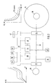
- a bicycle 2 is shown schematically in FIG. 1. Apart from the structural units to be described in more detail below, it is a conventional bicycle 2 which essentially consists of a frame 4, a front wheel fork 6, a handlebar 8, a saddle 10, a front wheel 12 and a rear wheel 14.
- a pedal crank 16 essentially consisting of two diametrical crank rods and one pedal at the end, is provided as in a conventional bicycle. However, there is no sprocket on the pedal crank 16, no sprocket on the hub of the rear wheel 14 and no chain between these two sprockets.
- a generator 18 for generating electrical power in the illustrated bicycle 2.
- the generator 18 has a larger diameter than the tube normally located there for receiving the bottom bracket.
- a rotor 52 of the generator 18 sits on the shaft 54 of the pedal crank 16, while on the inner circumference of the essentially cylindrical one Generator housing a stator, not shown, is provided (see Fig. 3). When the pedal crank 16 is rotated with muscle power, electrical power is generated in the generator 18.
- the electric motor / transmission unit 20 shown in more detail in FIG. 4 is provided in the bicycle 2 shown.
- the electric motor / transmission unit 20 When electrical power is supplied to this unit 20, it generates a torque driving the rear wheel 14.
- the generator 18 is assigned an electronic control 22 and the electric motor 26 of the electric motor / gear unit 20 is assigned an electronic control 24.
- a DC intermediate circuit 30 is located between the controls 22 and 24.
- the two controls 22 and 24 can also be spatially combined.
- the electronic control 22 of the generator 18 contains an actively controlled rectifier which determines the size of the electrical power coupled out from the generator 18 into the intermediate circuit 30. Actively controlled rectifiers are known so that they do not have to be described in more detail here.
- the assignment of an actively controlled rectifier to the generator 18 entails that the generator 18 opposes the user of the bicycle 2, who sets the pedal crank 16 in rotation, with a higher or lower rotational resistance, depending on the size of the extracted electrical power. With a high rotational resistance, the user must therefore apply a higher torque with his leg muscles in order to turn the pedal crank 16 without decreasing the speed, and vice versa.
- the electronic control 24 of the electric motor 26 has an active commutation of the electric motor 26 of the electric motor / transmission unit 20.
- the structure of electronic commutations for electric motors is known, so that detailed explanations for this are unnecessary.
- Control electronics 32 are connected to the electronic controls 22 and 24, which each function as power electronics. To the Control electronics 32 are connected to a plurality of operating elements 34, 36, 38, 40 which the vehicle user can operate by hand. By means of the first control element 34, the vehicle user can influence, via the control electronics 32 and the electronic control 22, the size of the electrical power fed into the intermediate circuit 30 and the manner in which the user generates this electrical power.
- the electrical power that is decoupled from the generator 18 and fed into the intermediate circuit 30 is - apart from low line and control losses - via the electronic control 24 fed to the electric motor 26.
- this torque M2 leads to an increase or decrease in the speed n2 and thus the driving speed v of the bicycle 2, which is proportionally related to this.
- Torque M2 because the product M2 x n2 must remain constant with the same generation of electrical power.
- the user can vary the speed n1 of the generator 18 and thus the generated electrical power P1 by pedaling faster or slower.
- the electric motor 26 with its electronic control 24 changes to a "higher" curve of constant power P2 (which, given the losses, is of course equal to the power P1), as shown at the top right in FIG. 2.
- P2 constant power
- a torque-speed characteristic curve of the generator 18 is shown in the top left of FIG. 2. From this characteristic curve it can be seen which torque M1 is required to rotate the generator 18 (at a constant speed) at a considered speed n1. It is not a "natural" torque-speed characteristic, e.g. would be present in a generator 18 with a downstream, passive, uncontrolled rectifier. Rather, it is a e.g. by means of the control electronics 32 and the electronic control 22 thereupon modified characteristic curve so that an at least essentially straight-line horizontal torque plateau is present for a certain speed range.
- the user can use the first control element 34 to change the electrical power P1 decoupled at a given speed n1.
- an automatic change in the output electrical power can be provided, preferably if the speed n1 comes down or up from a speed range that is comfortable for the user. It is also possible to make this predetermined range adjustable, e.g. via the second control element 36.
- the torque-speed characteristic of the generator 18 can be programmed by the user within certain limits. There is an interface for this, for example 42 of the control electronics 32 are provided to the outside. There you can connect an external computer to program the characteristic. This is preferably done before the start of the journey.
- the illustrated bicycle 2 also has a storage 44 for electrical energy, a solar cell device 46 and an internal combustion engine / generator unit 48.
- the memory 44 is a rechargeable battery with the best possible ratio of storage capacity to weight; alternatively, a non-rechargeable storage of electrical energy could be provided.
- the internal combustion engine / generator unit 48 is a small, high-speed internal combustion engine with a generator seated directly on the crankshaft.
- Each of the three sources 44, 46, 48 is connected on the output side to the intermediate circuit 30, and also to the control electronics 32 for control purposes. Both the solar cell device 46 and the internal combustion engine / generator unit 48 are electrically connected to the memory 44 (directly or via the DC link 30).
- the third control element 38 allows the user to determine whether and to what extent and from which of the sources 44, 46, 48 electrical power is fed into the intermediate circuit 30, either in addition to the electrical energy coming from the generator 18 or instead of this (for example when the user is about to take a certain break from pedaling).
- the memory 44 can be loaded from the intermediate circuit 30 and / or from the solar cell device 46 and / or from the internal combustion engine / generator unit 48.
- the user can also give the necessary commands for this via the third control element 38.
- Use of the solar cell device 46 is naturally advisable as soon as electrical power is generated there due to the presence of solar radiation can contribute electrical power for consumption in the electric motor 26 or use it to charge the memory 44 or can divide it between the two uses.
- Loading the memory 44 from the intermediate circuit 30 is advisable if one wants to increase the energy supply in the sense of a “stockpile” and is currently accepting slower progress with the bicycle 2.
- Commissioning of the internal combustion engine / generator unit 48 is particularly recommended when driving uphill for a long time or driving with a strong headwind or for sustainably charging the storage 44.
- Feeding electrical power from the storage 44 into the intermediate circuit 30 is particularly recommended as a starting aid or as an aid to Uphill.
- the solar cell device 46 can, for example, be of the type that is already commercially available for sailing yachts.
- the electronic control 24 of the electric motor 26 can be reversed via the control electronics 32 so that the electric motor 26 for braking the bicycle is switched to generator operation. It can be provided that the electrical power now generated by the electric motor 26 is converted into heat in a resistor 49 and / or is fed into the memory 44. In the latter case, it can be provided that the controller 24 then works as a rectifier.
- a further consumer 50 is shown on the bicycle 2 in FIG. 2.
- This can be, in particular, vehicle lighting or a radio or a tape player or a disc player for canned music, so that the driver can listen to music without using disposable batteries.
- Fig. 3 illustrates an embodiment of the compact housing of the generator 18 in an area where only the bottom bracket of the crank 16 sits.
- the diameter of the bottom bracket area is increased, and windings and pole teeth of the generator 18 (not shown) are provided on the inner circumference of the cylindrical housing thus created.
- Inside is the rotor 52 of the generator 18, which is occupied by permanent magnets.
- the arms 56 of the pedal crank 16 are fastened directly to the rotor shaft 54 which is guided to the right and left to the outside.
- the bearing crank 16 and the rotor 52 of the generator 18 are thus combined with one another. It is pointed out that between the pedal crankshaft and the rotor of the generator 18, a transmission gear can be provided in a higher speed.
- Fig. 4 illustrates an embodiment of the compact combination of the electric motor 26 with an axially adjacent planetary gear 60, both inside the hub 62 of the rear wheel 14. Due to the significant speed reduction that the planetary gear 60 provides, a very small electric motor 26 can be used . It can be seen that the electric motor 26 is constructed with an inner, stationary stator 64, which is seated on a fixed axis 66, and a cup-shaped rotor 68. The stator 64 has windings and pole teeth on its outer circumference, while the rotor 68 has permanent magnets on its inner circumference (both not shown). The rotor 68 is supported in one end region with a roller bearing in the hub 62 and in its other end region with a roller bearing on the axis 66.
- the rotor 68 is provided with a toothing which is known as Sun gear of the planetary gear 60 functions.
- the planet gears 70 of the planetary gear 60 sit on a planet gear carrier 72, which is fixed on the axis 66.
- the planet gears 70 mesh on the outside with an internal toothing 74 of the hub 62. It is alternatively possible to accommodate the planetary gear 60 at least partially in the interior of the stator 64. Finally, one can see spokes 76 which lead outward from the hub 20 to the wheel rim.
Landscapes
- Engineering & Computer Science (AREA)
- Chemical & Material Sciences (AREA)
- Combustion & Propulsion (AREA)
- Transportation (AREA)
- Mechanical Engineering (AREA)
- Electric Propulsion And Braking For Vehicles (AREA)
- Current-Collector Devices For Electrically Propelled Vehicles (AREA)
- Nonmetallic Welding Materials (AREA)
- Automatic Cycles, And Cycles In General (AREA)
- Arrangement And Mounting Of Devices That Control Transmission Of Motive Force (AREA)
- Control Of Eletrric Generators (AREA)
- Connection Of Motors, Electrical Generators, Mechanical Devices, And The Like (AREA)
Applications Claiming Priority (2)
| Application Number | Priority Date | Filing Date | Title |
|---|---|---|---|
| DE19600698A DE19600698A1 (de) | 1996-01-10 | 1996-01-10 | Mit Muskelkraft betreibbares Fahrzeug, insbesondere Fahrrad |
| DE19600698 | 1996-01-10 |
Publications (3)
| Publication Number | Publication Date |
|---|---|
| EP0784008A2 true EP0784008A2 (fr) | 1997-07-16 |
| EP0784008A3 EP0784008A3 (fr) | 1997-10-01 |
| EP0784008B1 EP0784008B1 (fr) | 2003-05-07 |
Family
ID=7782470
Family Applications (1)
| Application Number | Title | Priority Date | Filing Date |
|---|---|---|---|
| EP97100363A Expired - Lifetime EP0784008B1 (fr) | 1996-01-10 | 1997-01-10 | Véhicule propulsé par force musculaire |
Country Status (3)
| Country | Link |
|---|---|
| EP (1) | EP0784008B1 (fr) |
| AT (1) | ATE239639T1 (fr) |
| DE (2) | DE19600698A1 (fr) |
Cited By (14)
| Publication number | Priority date | Publication date | Assignee | Title |
|---|---|---|---|---|
| DE19732430A1 (de) * | 1997-07-28 | 1999-02-11 | Harald Kutze | Ein- oder mehrspuriges Muskel-Elektro-Hybrid-Fahrzeug |
| EP0980821A2 (fr) | 1998-08-18 | 2000-02-23 | Yamaha Hatsudoki Kabushiki Kaisha | Unité de propulsion pour une bicyclette avec moteur électrique |
| WO2000059773A2 (fr) | 1999-04-03 | 2000-10-12 | Swissmove Ag | Systeme de commande actionne par la force musculaire |
| FR2824043A1 (fr) * | 2001-04-27 | 2002-10-31 | Hichami Mohamed El | Dispositif pour l'entrainement sans chaine d'une roue de bicyclette |
| NL1018948C2 (nl) * | 2001-09-13 | 2003-03-20 | Sparta B V | Rijwiel met hulpaandrijving. |
| AT501842A1 (de) * | 2005-05-13 | 2006-11-15 | Spinwood Trading & Consulting | Fahrzeug |
| WO2006119531A1 (fr) | 2005-05-13 | 2006-11-16 | Spinwood Trading & Consulting Ltd. | Vehicule |
| AT502532B1 (de) * | 2005-08-16 | 2007-06-15 | Spinwood Trading & Consulting | Fahrzeug |
| WO2011035974A1 (fr) * | 2009-09-22 | 2011-03-31 | Robert Bosch Gmbh | Dispositif et procédé de régulation d'une récupération pour un véhicule actionné par une pédale |
| EP2384924A1 (fr) * | 2010-05-03 | 2011-11-09 | Tai-Her Yang | Véhicule électrique à pédale à transmission câblée asynchrone commandé par une puissance générée par un humain |
| EP2384923A1 (fr) * | 2010-05-03 | 2011-11-09 | Tai-Her Yang | Véhicule électrique à pédale à transmission câblée asynchrone commandé par une puissance générée par un humain |
| EP3360769A1 (fr) * | 2017-02-13 | 2018-08-15 | Mando Corporation | Bicyclette électrique et son procédé de commande |
| DE102013012208C5 (de) * | 2013-07-17 | 2019-07-04 | Institut für Automatisierung und Informatik GmbH Zentrum für industrielle Forschung und Entwicklung Wernigerode | Elektrisches Antriebssystem für ein mit Muskelkraft betriebenes Fahrzeug |
| CN113911255A (zh) * | 2021-10-30 | 2022-01-11 | 赫星(厦门)电子有限公司 | 一种智能自行车助力装置 |
Families Citing this family (42)
| Publication number | Priority date | Publication date | Assignee | Title |
|---|---|---|---|---|
| DE19855585B4 (de) * | 1998-12-02 | 2007-12-27 | Carbike Gmbh | Leichtfahrzeug mit einem Hybridantrieb aus Elektro-Muskelkraftantrieb |
| DE19937445C2 (de) * | 1999-08-07 | 2003-01-30 | Hans Peter Barbey | Antriebsverfahren für ein durch Muskelkraft zu bewegendes Fahrzeug |
| DE19955863A1 (de) * | 1999-11-20 | 2001-05-23 | Heinzmann Gmbh Co Kg Fritz | Fahrzeug mit Elektrohilfsantrieb |
| DE102010028645B4 (de) * | 2010-05-06 | 2022-01-20 | Robert Bosch Gmbh | Verfahren und Steuerungsvorrichtung zur Betätigung einer elektrischen Bremse eines Elektrofahrrads, Energieversorgungsvorrichtung mit der Steuerungsvorrichtung und elektrischer Antriebsstrang zum Antrieb eines Elektrofahrrads |
| DE102012017553A1 (de) * | 2012-09-05 | 2014-03-06 | Rid Ag | Elektroantrieb ohne Schaltgetriebe für E-Bikes |
| DE102013003287A1 (de) * | 2013-02-26 | 2014-08-28 | Ulrich Sommer | Elektronisches Steuerungs- und Batteriemanagamentsystem mit zusätzlichen Funktionen für Fahrräder mit elektrischem Zusatzantrieb |
| DE102013110347A1 (de) * | 2013-09-19 | 2015-03-19 | Flexmedia Electronics Corp. | Elektromechanisches Steuerungs- System für Muskelkraft betriebene Fahrzeuge |
| DE102013018716B4 (de) * | 2013-11-08 | 2020-03-12 | Peter Picciani | Fitnessgerät oder Nachrüstsatz für ein Fitnessgerät zur professionellen Stromgewinnung |
| DE102014000925A1 (de) | 2014-01-28 | 2015-07-30 | Philipp Graf von Magnis | Elektrofahrrad |
| DE102016210855B4 (de) | 2015-07-09 | 2021-03-18 | Ford Global Technologies, Llc | Hybrid-Fahrrad und Verfahren zum Steuern eines Antriebsmotors eines Hybrid-Fahrrads |
| WO2019076438A1 (fr) | 2017-10-16 | 2019-04-25 | Sveuciliste U Zagrebu Fakultet Elektrotehnike I Racunarstva | Système de propulsion électrique à propulsion humaine avec pédales découplées |
| DE102019006512A1 (de) * | 2019-09-13 | 2020-08-06 | Georg Egger | Rein durch Muskelkraft betriebenes Fahrzeug |
| DE102020128826A1 (de) | 2020-11-03 | 2022-05-05 | Schaeffler Technologies AG & Co. KG | Wolfromgetriebe |
| DE102021101189A1 (de) | 2021-01-21 | 2022-07-21 | Schaeffler Technologies AG & Co. KG | Antriebsanordnung für ein muskelbetriebenes Fahrzeug sowie Fahrzeug mit der Antriebsanordnung |
| DE102021102988A1 (de) | 2021-02-09 | 2022-08-11 | Schaeffler Technologies AG & Co. KG | Antriebsanordnung mit Verzögerungseinrichtung für muskelbetriebenes Fahrzeug, Fahrzeug mit der Antriebsanordnung sowie Verfahren |
| DE102021102992A1 (de) | 2021-02-09 | 2022-01-20 | Schaeffler Technologies AG & Co. KG | Antriebsanordnung für ein muskelbetriebenes Fahrzeug sowie Fahrzeug mit der Antriebsanordnung |
| DE102021102989B4 (de) | 2021-02-09 | 2022-09-15 | Schaeffler Technologies AG & Co. KG | Antriebsanordnung mit Exzentergetriebe für ein muskelbetriebenes Fahrzeug sowie Fahrzeug mit der Antriebsanordnung |
| DE102021108781B4 (de) | 2021-04-08 | 2023-01-05 | Schaeffler Technologies AG & Co. KG | Antriebsanordnung mit Exzentergetriebe für ein muskelbetriebenes Fahrzeug sowie Fahrzeug mit der Antriebsanordnung |
| DE102021108784B3 (de) | 2021-04-08 | 2022-06-23 | Schaeffler Technologies AG & Co. KG | Antriebsanordnung für ein muskelbetriebenes Fahrzeug mit Drehmomenterfassung sowie Fahrzeug mit der Antriebsanordnung |
| DE102021108788A1 (de) | 2021-04-08 | 2022-10-13 | Schaeffler Technologies AG & Co. KG | Exzenterwellenanordnung für ein Exzentergetriebe, Antriebsanordnung mit der Exzenterwellenanordnung, Fahrzeug mit der Antriebsanordnung sowie Verfahren zur Montage |
| DE102021109721A1 (de) | 2021-04-19 | 2022-10-20 | Schaeffler Technologies AG & Co. KG | Elektrisches Antriebssystem, Verfahren zur Steuerung eines elektrischen Antriebssystems, Computerprogrammprodukt und Steuereinheit |
| DE102021112219A1 (de) | 2021-05-11 | 2022-11-17 | Schaeffler Technologies AG & Co. KG | Generatormodul mit Exzentergetriebe für ein muskelbetriebenes Fahrzeug sowie Fahrzeug mit dem Generatormodul |
| DE102021112216A1 (de) | 2021-05-11 | 2022-11-17 | Schaeffler Technologies AG & Co. KG | Generatormodul mit Nassraum für ein muskelbetriebenes Fahrzeug sowie Fahrzeug mit dem Generatormodul |
| DE102021112782A1 (de) | 2021-05-18 | 2022-04-07 | Schaeffler Technologies AG & Co. KG | Exzentergetriebe, Generatormodul mit dem Exzentergetriebe, Aktormodul mit dem Exzentergetriebe sowie Fahrzeug mit dem Exzentergetriebe |
| DE102021114273A1 (de) | 2021-06-02 | 2022-12-08 | Schaeffler Technologies AG & Co. KG | Antriebsanordnung für muskelbetriebenes Fahrzeug sowie Fahrzeug mit der Antriebsanordnung |
| DE102021115271A1 (de) | 2021-06-14 | 2022-12-15 | Schaeffler Technologies AG & Co. KG | Antriebsanordnung für ein muskelbetriebenes Fahrzeug mit Temperaturerfassung sowie Fahrzeug mit der Antriebsanordnung |
| DE102021115929A1 (de) | 2021-06-21 | 2022-12-22 | Schaeffler Technologies AG & Co. KG | Kontrolleinrichtung für eine Antriebsanordnung, Antriebsanordnung mit der Kontrolleinrichtung, Fahrzeug mit der Antriebsanordnung sowie Verfahren |
| DE102021116078A1 (de) | 2021-06-22 | 2022-12-22 | Schaeffler Technologies AG & Co. KG | Antriebsanordnung mit zwei Antriebsmodulen für ein muskelbetriebenes Fahrzeug sowie Fahrzeug mit der Antriebsanordnung |
| DE102021117436A1 (de) | 2021-07-06 | 2023-01-12 | Schaeffler Technologies AG & Co. KG | Exzentergetriebe, Generatormodul mit dem Exzentergetriebe sowie Fahrzeug mit dem Exzentergetriebe |
| DE102021118294A1 (de) | 2021-07-15 | 2023-01-19 | Schaeffler Technologies AG & Co. KG | Exzentergetriebe, Generatormodul mit dem Exzentergetriebe sowie Fahrzeug mit dem Generatormodul |
| DE102021119145A1 (de) | 2021-07-23 | 2023-01-26 | Schaeffler Technologies AG & Co. KG | Antriebsanordnung für ein muskelbetriebenes Fahrzeug mit zwei baugleichen Getriebeeinrichtungen sowie Fahrzeug mit der Antriebsanordnung |
| DE102021119284A1 (de) | 2021-07-26 | 2023-01-26 | Schaeffler Technologies AG & Co. KG | Fahrrad mit exzentrisch angelenktem Hinterbau |
| DE102021129370A1 (de) | 2021-11-11 | 2023-05-11 | Schaeffler Technologies AG & Co. KG | Exzentergetriebe, Generatormodul mit dem Exzentergetriebe sowie Fahrzeug mit dem Generatormodul |
| DE102021129782A1 (de) | 2021-11-16 | 2023-05-17 | Schaeffler Technologies AG & Co. KG | Elektrisches Antriebssystem und generatorisch betreibbare Pedalliereinheit |
| DE102022101029A1 (de) | 2022-01-18 | 2023-07-20 | Schaeffler Technologies AG & Co. KG | Generatormodul für ein muskelkraftbetriebenes Fahrzeug sowie muskelkraftbetriebenes Fahrzeug mit dem Generatormodul |
| DE102022101158A1 (de) | 2022-01-19 | 2023-07-20 | Schaeffler Technologies AG & Co. KG | Generatormodul mit einer Anbindungsschnittstelle für einen Kühlkörper sowie muskelbetriebenes Fahrzeug mit dem Generatormodul |
| DE102022102239A1 (de) | 2022-02-01 | 2023-08-03 | Schaeffler Technologies AG & Co. KG | Antriebssystem für ein muskelbetriebenes Fahrzeug sowie Verfahren zur Nachrüstung einer Erfassungseinrichtung in dem Antriebsystem |
| DE102022102393A1 (de) | 2022-02-02 | 2023-08-03 | Schaeffler Technologies AG & Co. KG | Exzentergetriebe, Generatormodul mit dem Exzentergetriebe sowie Fahrzeug mit dem Generatormodul |
| DE102022116701A1 (de) | 2022-07-05 | 2023-05-11 | Schaeffler Technologies AG & Co. KG | Antriebsanordnung mit Exzentergetriebe für ein muskelbetriebenes Fahrzeug sowie Fahrzeug mit der Antriebsanordnung |
| DE102022002880A1 (de) | 2022-08-09 | 2024-02-15 | EGS Entwicklungsgesellschaft für Getriebesysteme mbH | Modulares Antriebssystem |
| DE102022003181A1 (de) | 2022-08-31 | 2024-02-29 | Benjamin Brammer | Verfahren für ein elektromechanisches Antriebssystem für ein mit Muskelkraft und elektrischer Energie betriebenes Fahrzeug |
| DE102022123121B3 (de) | 2022-09-12 | 2024-01-25 | Schaeffler Technologies AG & Co. KG | Antriebsanordnung und muskelbetriebenes Fahrzeug |
Citations (1)
| Publication number | Priority date | Publication date | Assignee | Title |
|---|---|---|---|---|
| EP0331180A1 (fr) | 1988-03-02 | 1989-09-06 | Heidelberg Motor Gesellschaft Fuer Energiekonverter Mbh | Machine électrique |
Family Cites Families (16)
| Publication number | Priority date | Publication date | Assignee | Title |
|---|---|---|---|---|
| CH44923A (fr) * | 1908-06-12 | 1909-10-01 | Riccardo Massone Carlo | Roue de véhicule à moteur électrique y incorporé |
| GB1231782A (fr) * | 1967-05-08 | 1971-05-12 | ||
| US3533484A (en) * | 1968-05-16 | 1970-10-13 | Garfield A Wood Jr | Electric power unit |
| US3884317A (en) * | 1974-03-05 | 1975-05-20 | Augustus B Kinzel | Electrically powered cycle |
| DE3003026A1 (de) * | 1980-01-29 | 1981-07-30 | Wolfgang Dr.-Ing. 8740 Bad Neustadt Volkrodt | Batteriegespeister, elektromotorischer antrieb fuer fahrraeder |
| US4516647A (en) * | 1982-02-08 | 1985-05-14 | Thaddeus Novak | Solar powered vehicle |
| SE8302022L (sv) * | 1983-04-12 | 1984-10-13 | Ake Enoksson | Drivlina for cykel |
| IL71233A (en) * | 1984-03-14 | 1986-11-30 | Iliya Goldenfeld | Auxiliary drive for pedal-driven road vehicles |
| DE3525059A1 (de) * | 1985-07-13 | 1987-01-22 | Ruedell Christian | Drei komponenten antrieb, bestehend aus solarenergie, batterieenergie und muskelkraft, vereinigt in einem antriebssystem |
| DE3623800A1 (de) * | 1985-10-24 | 1987-04-30 | Binder Aviat Gmbh | Fahrrad mit zuschaltbarem motorantrieb |
| DE3719486A1 (de) * | 1987-06-11 | 1988-12-29 | Siegfried Baltzer | Stufenlose drehmomentwandlung fuer fahrraeder mit kraftuebertragung durch elektrische leiter |
| DE3826386C2 (de) * | 1988-08-03 | 2000-06-21 | Fhp Motors Gmbh | Elektromotorischer Hilfsantrieb für Fahrräder |
| US4871042A (en) * | 1988-09-01 | 1989-10-03 | Hsu Chi Chu | Electric bicycle |
| DE9302621U1 (de) * | 1992-07-10 | 1993-06-24 | Drozdowicz, Ryszard, 1000 Berlin | Fahrzeug mit kombiniertem, zuschaltbarem Hilfsantrieb |
| DE4333638A1 (de) * | 1993-10-02 | 1995-04-06 | Rene Goetze | Generator betrieben durch Muskelkraft zum Antrieb elektrisch betriebener Fahrzeuge |
| DE4344008C2 (de) * | 1993-12-23 | 1996-09-05 | Itg Engineering Gmbh Zschopau | Fahrrad mit Hybridantrieb |
-
1996
- 1996-01-10 DE DE19600698A patent/DE19600698A1/de not_active Ceased
-
1997
- 1997-01-10 DE DE59709997T patent/DE59709997D1/de not_active Expired - Lifetime
- 1997-01-10 EP EP97100363A patent/EP0784008B1/fr not_active Expired - Lifetime
- 1997-01-10 AT AT97100363T patent/ATE239639T1/de not_active IP Right Cessation
Patent Citations (1)
| Publication number | Priority date | Publication date | Assignee | Title |
|---|---|---|---|---|
| EP0331180A1 (fr) | 1988-03-02 | 1989-09-06 | Heidelberg Motor Gesellschaft Fuer Energiekonverter Mbh | Machine électrique |
Cited By (24)
| Publication number | Priority date | Publication date | Assignee | Title |
|---|---|---|---|---|
| DE19732430A1 (de) * | 1997-07-28 | 1999-02-11 | Harald Kutze | Ein- oder mehrspuriges Muskel-Elektro-Hybrid-Fahrzeug |
| EP0980821A2 (fr) | 1998-08-18 | 2000-02-23 | Yamaha Hatsudoki Kabushiki Kaisha | Unité de propulsion pour une bicyclette avec moteur électrique |
| EP0980821A3 (fr) * | 1998-08-18 | 2004-01-02 | Yamaha Hatsudoki Kabushiki Kaisha | Unité de propulsion pour une bicyclette avec moteur électrique |
| WO2000059773A2 (fr) | 1999-04-03 | 2000-10-12 | Swissmove Ag | Systeme de commande actionne par la force musculaire |
| WO2000059773A3 (fr) * | 1999-04-03 | 2001-07-12 | Swissmove Ag | Systeme de commande actionne par la force musculaire |
| FR2824043A1 (fr) * | 2001-04-27 | 2002-10-31 | Hichami Mohamed El | Dispositif pour l'entrainement sans chaine d'une roue de bicyclette |
| NL1018948C2 (nl) * | 2001-09-13 | 2003-03-20 | Sparta B V | Rijwiel met hulpaandrijving. |
| WO2003022671A3 (fr) * | 2001-09-13 | 2003-08-21 | Sparta B V | Bicyclette a propulsion auxiliaire |
| EP1425211B2 (fr) † | 2001-09-13 | 2011-09-21 | Sparta B.V. | Bicyclette a propulsion auxiliaire |
| US7779948B2 (en) | 2005-05-13 | 2010-08-24 | Spinwood Trading & Consulting Ltd. | Vehicle |
| AT501842A1 (de) * | 2005-05-13 | 2006-11-15 | Spinwood Trading & Consulting | Fahrzeug |
| AT501842B1 (de) * | 2005-05-13 | 2008-05-15 | Spinwood Trading & Consulting | Fahrzeug |
| WO2006119531A1 (fr) | 2005-05-13 | 2006-11-16 | Spinwood Trading & Consulting Ltd. | Vehicule |
| AT502532B1 (de) * | 2005-08-16 | 2007-06-15 | Spinwood Trading & Consulting | Fahrzeug |
| US9550489B2 (en) | 2009-09-22 | 2017-01-24 | Robert Bosch Gmbh | Device and method for regulating an energy recovery in a pedal-driven vehicle |
| CN102510826A (zh) * | 2009-09-22 | 2012-06-20 | 罗伯特·博世有限公司 | 用于在踏板传动式交通工具中调节再生利用的装置和方法 |
| CN102510826B (zh) * | 2009-09-22 | 2015-08-26 | 罗伯特·博世有限公司 | 用于在踏板传动式交通工具中调节再生利用的装置和方法 |
| WO2011035974A1 (fr) * | 2009-09-22 | 2011-03-31 | Robert Bosch Gmbh | Dispositif et procédé de régulation d'une récupération pour un véhicule actionné par une pédale |
| EP2384924A1 (fr) * | 2010-05-03 | 2011-11-09 | Tai-Her Yang | Véhicule électrique à pédale à transmission câblée asynchrone commandé par une puissance générée par un humain |
| EP2384923A1 (fr) * | 2010-05-03 | 2011-11-09 | Tai-Her Yang | Véhicule électrique à pédale à transmission câblée asynchrone commandé par une puissance générée par un humain |
| DE102013012208C5 (de) * | 2013-07-17 | 2019-07-04 | Institut für Automatisierung und Informatik GmbH Zentrum für industrielle Forschung und Entwicklung Wernigerode | Elektrisches Antriebssystem für ein mit Muskelkraft betriebenes Fahrzeug |
| EP3360769A1 (fr) * | 2017-02-13 | 2018-08-15 | Mando Corporation | Bicyclette électrique et son procédé de commande |
| CN113911255A (zh) * | 2021-10-30 | 2022-01-11 | 赫星(厦门)电子有限公司 | 一种智能自行车助力装置 |
| CN113911255B (zh) * | 2021-10-30 | 2023-10-24 | 赫星(厦门)电子有限公司 | 一种智能自行车助力装置 |
Also Published As
| Publication number | Publication date |
|---|---|
| EP0784008A3 (fr) | 1997-10-01 |
| DE59709997D1 (de) | 2003-06-12 |
| DE19600698A1 (de) | 1997-08-07 |
| EP0784008B1 (fr) | 2003-05-07 |
| ATE239639T1 (de) | 2003-05-15 |
Similar Documents
| Publication | Publication Date | Title |
|---|---|---|
| EP0784008B1 (fr) | Véhicule propulsé par force musculaire | |
| EP1165188B1 (fr) | Systeme de commande actionne par la force musculaire | |
| DE60214777T2 (de) | Kinderfahrzeug mit elektronischer geschwindigkeitssteuerung | |
| DE102013012208C5 (de) | Elektrisches Antriebssystem für ein mit Muskelkraft betriebenes Fahrzeug | |
| EP3486154B1 (fr) | Entrainement hybride pour une bicyclette électrique | |
| EP1879790B1 (fr) | Vehicule | |
| EP2218634B1 (fr) | Système de transmission de bicyclette | |
| US5316101A (en) | Electric and pedal driven bicycle with solar charging | |
| DE102009045447B4 (de) | Fahrrad mit elektrischem Hilfsantrieb | |
| DE102012024071B4 (de) | Fahrradgenerator- und/oder Schaltvorrichtung | |
| CN103770900B (zh) | 一种自行车 | |
| DE102007050552B3 (de) | Elektrofahrzeug mit einer Motorsteuerung über eine Tretkurbel | |
| DE2253223A1 (de) | Elektrischer fahrzeugantrieb | |
| WO1991019637A1 (fr) | Engrenage planetaire pour vehicules hybrides | |
| CN113993777B (zh) | 电动辅助脚踏车 | |
| EP4185514A1 (fr) | Procédé de commande d'un dispositif d'entraînement d'une bicyclette, dispositif d'entraînement pour une bicyclette et bicyclette | |
| EP4228958B1 (fr) | Unité d'entraînement pour un moyen de locomotion pouvant être entraîné simultanément par une force musculaire humaine et des moteurs électriques | |
| DE102014000925A1 (de) | Elektrofahrrad | |
| DE102012104150A1 (de) | Fahrzeug, insbesondere Fahrrad, mit elektrischem Hilfsantrieb | |
| DE4446219A1 (de) | Kraftfahrzeug mit mehreren Elektromotoren | |
| DE102021109722A1 (de) | Elektrisches Antriebssystem | |
| DE2436546A1 (de) | Antriebsaggregat | |
| WO2013057294A1 (fr) | Procédé de fonctionnement d'un vélo électrique | |
| DE3826386C2 (de) | Elektromotorischer Hilfsantrieb für Fahrräder | |
| DE102018131682A1 (de) | Antriebsstrang für Fahrzeuge mit Pedalantrieb |
Legal Events
| Date | Code | Title | Description |
|---|---|---|---|
| PUAI | Public reference made under article 153(3) epc to a published international application that has entered the european phase |
Free format text: ORIGINAL CODE: 0009012 |
|
| AK | Designated contracting states |
Kind code of ref document: A2 Designated state(s): AT BE CH DE DK ES FR GB IT LI NL |
|
| PUAL | Search report despatched |
Free format text: ORIGINAL CODE: 0009013 |
|
| AK | Designated contracting states |
Kind code of ref document: A3 Designated state(s): AT BE CH DE DK ES FR GB IT LI NL |
|
| 17P | Request for examination filed |
Effective date: 19980113 |
|
| 17Q | First examination report despatched |
Effective date: 20000602 |
|
| GRAH | Despatch of communication of intention to grant a patent |
Free format text: ORIGINAL CODE: EPIDOS IGRA |
|
| GRAH | Despatch of communication of intention to grant a patent |
Free format text: ORIGINAL CODE: EPIDOS IGRA |
|
| GRAA | (expected) grant |
Free format text: ORIGINAL CODE: 0009210 |
|
| AK | Designated contracting states |
Designated state(s): AT BE CH DE DK ES FR GB IT LI NL |
|
| PG25 | Lapsed in a contracting state [announced via postgrant information from national office to epo] |
Ref country code: GB Free format text: LAPSE BECAUSE OF FAILURE TO SUBMIT A TRANSLATION OF THE DESCRIPTION OR TO PAY THE FEE WITHIN THE PRESCRIBED TIME-LIMIT Effective date: 20030507 |
|
| REG | Reference to a national code |
Ref country code: GB Ref legal event code: FG4D Free format text: NOT ENGLISH |
|
| REG | Reference to a national code |
Ref country code: CH Ref legal event code: NV Representative=s name: BUECHEL, VON REVY & PARTNER Ref country code: CH Ref legal event code: EP |
|
| REF | Corresponds to: |
Ref document number: 59709997 Country of ref document: DE Date of ref document: 20030612 Kind code of ref document: P |
|
| PG25 | Lapsed in a contracting state [announced via postgrant information from national office to epo] |
Ref country code: DK Free format text: LAPSE BECAUSE OF FAILURE TO SUBMIT A TRANSLATION OF THE DESCRIPTION OR TO PAY THE FEE WITHIN THE PRESCRIBED TIME-LIMIT Effective date: 20030807 |
|
| PG25 | Lapsed in a contracting state [announced via postgrant information from national office to epo] |
Ref country code: ES Free format text: LAPSE BECAUSE OF FAILURE TO SUBMIT A TRANSLATION OF THE DESCRIPTION OR TO PAY THE FEE WITHIN THE PRESCRIBED TIME-LIMIT Effective date: 20030818 |
|
| GBV | Gb: ep patent (uk) treated as always having been void in accordance with gb section 77(7)/1977 [no translation filed] |
Effective date: 20030507 |
|
| ET | Fr: translation filed | ||
| PG25 | Lapsed in a contracting state [announced via postgrant information from national office to epo] |
Ref country code: AT Free format text: LAPSE BECAUSE OF NON-PAYMENT OF DUE FEES Effective date: 20040110 |
|
| PGFP | Annual fee paid to national office [announced via postgrant information from national office to epo] |
Ref country code: NL Payment date: 20040119 Year of fee payment: 8 |
|
| PGFP | Annual fee paid to national office [announced via postgrant information from national office to epo] |
Ref country code: CH Payment date: 20040129 Year of fee payment: 8 |
|
| PG25 | Lapsed in a contracting state [announced via postgrant information from national office to epo] |
Ref country code: BE Free format text: LAPSE BECAUSE OF NON-PAYMENT OF DUE FEES Effective date: 20040131 |
|
| PLBE | No opposition filed within time limit |
Free format text: ORIGINAL CODE: 0009261 |
|
| STAA | Information on the status of an ep patent application or granted ep patent |
Free format text: STATUS: NO OPPOSITION FILED WITHIN TIME LIMIT |
|
| 26N | No opposition filed |
Effective date: 20040210 |
|
| BERE | Be: lapsed |
Owner name: *MAGNET-MOTOR G.- FUR MAGNETMOTORISCHE TECHNIK M.B Effective date: 20040131 |
|
| PG25 | Lapsed in a contracting state [announced via postgrant information from national office to epo] |
Ref country code: FR Free format text: LAPSE BECAUSE OF NON-PAYMENT OF DUE FEES Effective date: 20040930 |
|
| REG | Reference to a national code |
Ref country code: FR Ref legal event code: ST |
|
| PG25 | Lapsed in a contracting state [announced via postgrant information from national office to epo] |
Ref country code: IT Free format text: LAPSE BECAUSE OF NON-PAYMENT OF DUE FEES Effective date: 20050110 |
|
| PG25 | Lapsed in a contracting state [announced via postgrant information from national office to epo] |
Ref country code: LI Free format text: LAPSE BECAUSE OF NON-PAYMENT OF DUE FEES Effective date: 20050131 Ref country code: CH Free format text: LAPSE BECAUSE OF NON-PAYMENT OF DUE FEES Effective date: 20050131 |
|
| PG25 | Lapsed in a contracting state [announced via postgrant information from national office to epo] |
Ref country code: NL Free format text: LAPSE BECAUSE OF NON-PAYMENT OF DUE FEES Effective date: 20050801 |
|
| REG | Reference to a national code |
Ref country code: CH Ref legal event code: PL |
|
| NLV4 | Nl: lapsed or anulled due to non-payment of the annual fee |
Effective date: 20050801 |
|
| PGFP | Annual fee paid to national office [announced via postgrant information from national office to epo] |
Ref country code: DE Payment date: 20150326 Year of fee payment: 19 |
|
| REG | Reference to a national code |
Ref country code: DE Ref legal event code: R119 Ref document number: 59709997 Country of ref document: DE |
|
| PG25 | Lapsed in a contracting state [announced via postgrant information from national office to epo] |
Ref country code: DE Free format text: LAPSE BECAUSE OF NON-PAYMENT OF DUE FEES Effective date: 20160802 |