EP0783209A1 - Verfahren und Vorrichtung zur drahtloser Übertragung - Google Patents
Verfahren und Vorrichtung zur drahtloser Übertragung Download PDFInfo
- Publication number
- EP0783209A1 EP0783209A1 EP96402894A EP96402894A EP0783209A1 EP 0783209 A1 EP0783209 A1 EP 0783209A1 EP 96402894 A EP96402894 A EP 96402894A EP 96402894 A EP96402894 A EP 96402894A EP 0783209 A1 EP0783209 A1 EP 0783209A1
- Authority
- EP
- European Patent Office
- Prior art keywords
- signal
- stage
- frequency
- carrier
- amplitude
- Prior art date
- Legal status (The legal status is an assumption and is not a legal conclusion. Google has not performed a legal analysis and makes no representation as to the accuracy of the status listed.)
- Granted
Links
- 238000000034 method Methods 0.000 title claims abstract description 28
- 230000005540 biological transmission Effects 0.000 title claims description 13
- 230000005236 sound signal Effects 0.000 claims abstract description 4
- 238000001914 filtration Methods 0.000 claims description 18
- 230000003321 amplification Effects 0.000 claims description 9
- 238000003199 nucleic acid amplification method Methods 0.000 claims description 9
- 230000008054 signal transmission Effects 0.000 claims description 4
- 238000001228 spectrum Methods 0.000 description 6
- 239000000969 carrier Substances 0.000 description 2
- 238000011084 recovery Methods 0.000 description 1
- 230000035945 sensitivity Effects 0.000 description 1
Images


Classifications
-
- H—ELECTRICITY
- H04—ELECTRIC COMMUNICATION TECHNIQUE
- H04B—TRANSMISSION
- H04B1/00—Details of transmission systems, not covered by a single one of groups H04B3/00 - H04B13/00; Details of transmission systems not characterised by the medium used for transmission
- H04B1/38—Transceivers, i.e. devices in which transmitter and receiver form a structural unit and in which at least one part is used for functions of transmitting and receiving
- H04B1/40—Circuits
-
- H—ELECTRICITY
- H04—ELECTRIC COMMUNICATION TECHNIQUE
- H04R—LOUDSPEAKERS, MICROPHONES, GRAMOPHONE PICK-UPS OR LIKE ACOUSTIC ELECTROMECHANICAL TRANSDUCERS; DEAF-AID SETS; PUBLIC ADDRESS SYSTEMS
- H04R5/00—Stereophonic arrangements
- H04R5/02—Spatial or constructional arrangements of loudspeakers
-
- H—ELECTRICITY
- H04—ELECTRIC COMMUNICATION TECHNIQUE
- H04R—LOUDSPEAKERS, MICROPHONES, GRAMOPHONE PICK-UPS OR LIKE ACOUSTIC ELECTROMECHANICAL TRANSDUCERS; DEAF-AID SETS; PUBLIC ADDRESS SYSTEMS
- H04R5/00—Stereophonic arrangements
- H04R5/04—Circuit arrangements, e.g. for selective connection of amplifier inputs/outputs to loudspeakers, for loudspeaker detection, or for adaptation of settings to personal preferences or hearing impairments
Definitions
- the present invention relates to a method and a device for wireless transmission of a signal S 1 between a transmitter and at least one receiver.
- the invention relates particularly to a method and a device for wireless transmission of an audio signal between a television set and at least two speakers located at a distance from said television set.
- the known wireless transmission methods are based on modulation of a carrier whose frequency is located in the infrared (IR) range.
- the waves representing the IR signals have a mono-directional propagation and therefore undergo interruptions due to obstacles likely to be between the transmitter and the receiver.
- the transmitter and the receiver (s) must be very well aligned. Consequently, the use of IR frequency carriers is incompatible with environments, such as a television room for example, in which, to obtain a good sound distribution, the speakers must be located symmetrically on diagonals and at a distance of the television set as shown in Figure 1.
- LEDs highly sensitive light-emitting diodes
- Another advantage of the method according to the invention comes from the implementation of a double FM-AM modulation allowing a significant simplification of the receiver. Indeed, the recovery of the signal S 3m is carried out by a demodulation of conventional amplitude requiring inexpensive components.
- the transmission of a SHF signal requires a local oscillator having a relatively modest frequency stability and therefore inexpensive, compared to the required stability, both at transmission than reception, by the oscillators used in a conventional frequency modulation system.
- the method according to the invention is implemented by means of a wireless transmission device between a transmitter and a receiver.
- the transmitter comprises three stages connected in cascade, namely a first stage of amplification / filtering of the signal S 1 , a second stage of frequency modulation of the carrier S 2 and a third stage of amplitude modulation of the carrier S 3
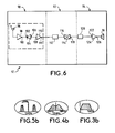
- the receiver comprises three stages connected in cascade, that is a first stage of demodulation of amplitude of the signal S 3m , a second stage of demodulation of frequency of the signal S 2m and a third stage of amplification / filtering of the signal S 1 received.
- a carrier S 2 of frequency 1 MHz is modulated by an audio signal S 1 sent by a television set 14 to two speakers 16 and 18 located at a distance from said television apparatus 14.
- the frequency modulation of the carrier S 2 by the signal S 1 makes it possible to obtain a maximum excursion of frequency ⁇ F of ⁇ 100 KHz , around the frequency F 2 .
- the frequency excursion ⁇ F being proportional to the amplitude of the signal S 1 , it follows that the adjustment of the sound level of the speakers 16 and 18 is obtained by the adjustment of said frequency excursion ⁇ F. With such a method, there is no need to use an additional channel to control the sound level of the speakers.
- the carrier S 3 has a frequency F3 equal to 5.8 GHz.
- the spectrum of the signal S 3m obtained by the amplitude modulation of the carrier S 3 and represented by FIGS. 5a and 5b, comprises a central line representing the frequency F 3 , and two lateral bands, representing the modulating signal S 2m, , centered on the frequency F2.
- the method according to the invention is implemented by a wireless transmission device comprising the transmitter 10 and the receiver 12 shown diagrammatically in FIGS. 2 and 6.
- the transmitter 10 comprises three stages connected in cascade, ie a first stage 20 of amplification / filtering of the signal S 1 to be transmitted, a second stage 22 of frequency modulation of the carrier S 2 and a third stage 24 of amplitude modulation of the carrier S 3 .
- the stage 20 comprises a first audio amplifier 30 whose input 32 receives the signal S 1 and whose output 34 is connected to a first filtering means 36, a second audio amplifier 38 whose input 40 receives, from filtering means 36, the signal S 1 preamplified and filtered and whose output 42 is connected to the frequency modulation stage 22.
- Said frequency modulation stage 22 comprises an oscillator RF (radio frequency) 50 voltage controlled (VCO) intended to generate the signal S 2 and of which an input 44 receives the signal S 1 , while an output 52 delivers the signal S 2m resulting from the frequency modulation of said signal S 2 by the signal S 1 , to a first RF amplifier 54, an output 58 of said first RF amplifier 54 is connected to an input 60 of a second filter means 62 of which an output 64 is connected to an input 66 of a second amplifier R F 68. An output 70 of said second RF amplifier 68 is connected to the amplitude modulation stage 24.
- RF radio frequency
- VCO voltage controlled
- Said amplitude modulation stage 24 includes a SHF (super high frequency) oscillator 80 intended to generate the carrier S 3 and delivering to an output 82 the signal S 3m resulting from the modulation amplitude of said carrier S 3 by the signal S 2m .
- the output 82 of said SHF oscillator 80 is connected to an antenna 84 intended to transmit the signal S 3m to the receiver 12.
- the receiver 12, represented in FIG. 6, comprises three stages connected in cascade, either a first stage 90 of demodulation of amplitude of the signal S 3m , a second stage 92 of demodulation of frequency of the signal S 2m , and a third stage 94 for amplification / filtering of the signal S 1 received.
- Stage 90 comprises an antenna 96 for receiving the signal S 2m connected to a preamplification means 98, an output 100 of which is connected to a first terminal 102 of an AM detector 104; a second terminal 106 of said AM detector 104 is connected to an input 108 of a high impedance amplification means 110, one output of which is connected to stage 92.
- Said stage 92 comprises a third filtering means 112, connected to a input 116 of a frequency demodulator 114 including an output 118 delivers the signal S 1 to stage 94.
- Stage 94 includes a fourth filtering means 120 connected to an input 122 of a third audio amplifier 124, an output 126 of which is connected to a loudspeaker 16.
- the signal to be transmitted S 1 is applied to the input 44 of the RF oscillator 50 so as to frequency-modulate the carrier S 2 generated by said RF oscillator 50.
- the signal S 2m obtained is then amplified and filtered, then applied to the input of the SHF 80 oscillator so as to amplitude-modulate the carrier S 3 generated by said oscillator 80.
- the signal S 3m obtained is then emitted by the antenna 84 to the antenna 96.
- the signal S 3m is preamplified by the preamplifier 98 then applied to the AM detector 104 so as to recover the modulating signal S 2m , the spectrum of which is shown in FIG. 4b.
- the signal S 2m is then applied to a frequency demodulator 144, via the filtering means 112.
- Said demodulator 114 delivers at its output 118 the signal S 1 which is then sent to the loudspeaker 16 via the filtering means 120.
- the transmitted signal is immune to disturbances such as ambient light and obstacles liable to cause interruptions of the transmitter-receiver link.
- the structure of the receiver used is considerably simplified.
Landscapes
- Engineering & Computer Science (AREA)
- Signal Processing (AREA)
- Physics & Mathematics (AREA)
- Acoustics & Sound (AREA)
- Computer Networks & Wireless Communication (AREA)
- Transmitters (AREA)
- Television Receiver Circuits (AREA)
- Radio Transmission System (AREA)
Applications Claiming Priority (2)
| Application Number | Priority Date | Filing Date | Title |
|---|---|---|---|
| FR9515742A FR2743232B1 (fr) | 1995-12-29 | 1995-12-29 | Procede et dispositif de transmission sans fil |
| FR9515742 | 1995-12-29 |
Publications (2)
| Publication Number | Publication Date |
|---|---|
| EP0783209A1 true EP0783209A1 (de) | 1997-07-09 |
| EP0783209B1 EP0783209B1 (de) | 2005-04-13 |
Family
ID=9486150
Family Applications (1)
| Application Number | Title | Priority Date | Filing Date |
|---|---|---|---|
| EP96402894A Expired - Lifetime EP0783209B1 (de) | 1995-12-29 | 1996-12-26 | Verfahren und Vorrichtung zur drahtloser Übertragung |
Country Status (6)
| Country | Link |
|---|---|
| US (1) | US5960090A (de) |
| EP (1) | EP0783209B1 (de) |
| JP (1) | JP3898790B2 (de) |
| CN (1) | CN1091327C (de) |
| DE (1) | DE69634592T2 (de) |
| FR (1) | FR2743232B1 (de) |
Cited By (2)
| Publication number | Priority date | Publication date | Assignee | Title |
|---|---|---|---|---|
| WO1999018676A1 (de) * | 1997-10-01 | 1999-04-15 | Jens Kurrat | Vorrichtung zur übertragung amplitudengetasteter mikrowellensignale |
| CN105848034A (zh) * | 2016-05-03 | 2016-08-10 | 深圳市八达晟电子有限公司 | 光纤解码5.8g无线游戏耳机及其控制方法 |
Families Citing this family (3)
| Publication number | Priority date | Publication date | Assignee | Title |
|---|---|---|---|---|
| US20040086141A1 (en) * | 2002-08-26 | 2004-05-06 | Robinson Arthur E. | Wearable buddy audio system |
| US7497298B2 (en) * | 2004-06-22 | 2009-03-03 | Caterpillar Inc. | Machine joystick control system |
| CN110289876B (zh) * | 2019-07-25 | 2024-04-19 | 广东圣大电子有限公司 | 一种vhf微波跳频电台接收机 |
Citations (3)
| Publication number | Priority date | Publication date | Assignee | Title |
|---|---|---|---|---|
| US4349842A (en) * | 1979-11-09 | 1982-09-14 | U.S. Philips Corporation | Television receiver for receiving a picture carrier whose amplitude is modulated with a video signal, and a sound carrier whose frequency is modulated with an audio signal |
| EP0432052A2 (de) * | 1989-12-08 | 1991-06-12 | Sony Corporation | RF-Modulator |
| EP0471477A1 (de) * | 1990-08-14 | 1992-02-19 | Sony Corporation | Drahtloser Empfänger |
Family Cites Families (3)
| Publication number | Priority date | Publication date | Assignee | Title |
|---|---|---|---|---|
| US4660192A (en) * | 1985-04-11 | 1987-04-21 | Pomatto Sr Robert P | Simultaneous AM and FM transmitter and receiver |
| DE69322393T2 (de) * | 1992-07-30 | 1999-05-27 | Clair Bros. Audio Enterprises, Inc., Lititz, Pa. | Konzertbeschallungssystem |
| US5666422A (en) * | 1994-05-18 | 1997-09-09 | Harrison; Robert W. | Remote speaker for surround-sound applications |
-
1995
- 1995-12-29 FR FR9515742A patent/FR2743232B1/fr not_active Expired - Fee Related
-
1996
- 1996-12-19 US US08/770,095 patent/US5960090A/en not_active Expired - Lifetime
- 1996-12-19 JP JP33990496A patent/JP3898790B2/ja not_active Expired - Fee Related
- 1996-12-26 EP EP96402894A patent/EP0783209B1/de not_active Expired - Lifetime
- 1996-12-26 CN CN96116731.9A patent/CN1091327C/zh not_active Expired - Fee Related
- 1996-12-26 DE DE69634592T patent/DE69634592T2/de not_active Expired - Lifetime
Patent Citations (3)
| Publication number | Priority date | Publication date | Assignee | Title |
|---|---|---|---|---|
| US4349842A (en) * | 1979-11-09 | 1982-09-14 | U.S. Philips Corporation | Television receiver for receiving a picture carrier whose amplitude is modulated with a video signal, and a sound carrier whose frequency is modulated with an audio signal |
| EP0432052A2 (de) * | 1989-12-08 | 1991-06-12 | Sony Corporation | RF-Modulator |
| EP0471477A1 (de) * | 1990-08-14 | 1992-02-19 | Sony Corporation | Drahtloser Empfänger |
Cited By (2)
| Publication number | Priority date | Publication date | Assignee | Title |
|---|---|---|---|---|
| WO1999018676A1 (de) * | 1997-10-01 | 1999-04-15 | Jens Kurrat | Vorrichtung zur übertragung amplitudengetasteter mikrowellensignale |
| CN105848034A (zh) * | 2016-05-03 | 2016-08-10 | 深圳市八达晟电子有限公司 | 光纤解码5.8g无线游戏耳机及其控制方法 |
Also Published As
| Publication number | Publication date |
|---|---|
| EP0783209B1 (de) | 2005-04-13 |
| CN1156350A (zh) | 1997-08-06 |
| DE69634592T2 (de) | 2006-03-09 |
| JPH09200100A (ja) | 1997-07-31 |
| FR2743232A1 (fr) | 1997-07-04 |
| DE69634592D1 (de) | 2005-05-19 |
| CN1091327C (zh) | 2002-09-18 |
| FR2743232B1 (fr) | 1998-01-30 |
| US5960090A (en) | 1999-09-28 |
| JP3898790B2 (ja) | 2007-03-28 |
Similar Documents
| Publication | Publication Date | Title |
|---|---|---|
| EP0785635B1 (de) | Verfahren und Anordnung zur Übertragung mit Frequenzdiversity unter Verwendung von mehreren unkorrelierten Trägern | |
| EP0314101B1 (de) | Radiofrequenzoptisches Übertragungssystem, besonders für Satellitenfunken | |
| US20070274713A1 (en) | System and method for subcarrier modulation as supervisory channel | |
| US5784506A (en) | Frequency-encoded optical CDMA transmission system and optical receiver therefor | |
| US6031648A (en) | Automatic gain control for free-space optical telecommunications links | |
| US7509047B2 (en) | System and method for subcarrier modulation in ISM band as supervisory channel | |
| JP2004505541A (ja) | 無線光通信システムのトーン・トラッキングの方法および装置 | |
| EP0783209B1 (de) | Verfahren und Vorrichtung zur drahtloser Übertragung | |
| JPH05227103A (ja) | 光通信方法 | |
| US5335107A (en) | Method and apparatus for modulation of self-pulsating diode laser's self-pulsating frequency | |
| JPS5915226B2 (ja) | 無線通信システム | |
| EP0889619B1 (de) | FSK-Modulator mit Phasenregelschleife | |
| CN110381419A (zh) | 一种无线麦克风系统及其信号传输方法 | |
| JP2004080350A (ja) | 高周波信号伝送システム | |
| FR2719426A1 (fr) | Procédé et dispositif de réception d'au moins un signal d'entrée comprenant au moins une information codée, et d'extraction de cette information. | |
| JP3324520B2 (ja) | 利得制御回路 | |
| KR0124837Y1 (ko) | 평형변조방식 무선헤드폰장치 | |
| Naito et al. | Optimum system parameters for multigigabit CPFSK optical heterodyne detection systems | |
| JPH06152565A (ja) | コヒーレント光伝送装置 | |
| KR20040102941A (ko) | 광신호의 클럭 추출장치 및 방법 | |
| JP2004048583A5 (de) | ||
| JPS63198425A (ja) | 中間周波数安定化方法 | |
| JP2000341218A (ja) | 光送受信システム、光受信装置、および光送受信方法 | |
| JPH10209974A (ja) | 受信装置 | |
| JPH11127119A (ja) | 光伝送装置及び光伝送方法 |
Legal Events
| Date | Code | Title | Description |
|---|---|---|---|
| PUAI | Public reference made under article 153(3) epc to a published international application that has entered the european phase |
Free format text: ORIGINAL CODE: 0009012 |
|
| AK | Designated contracting states |
Kind code of ref document: A1 Designated state(s): DE FR GB IT |
|
| 17P | Request for examination filed |
Effective date: 19980109 |
|
| RAP1 | Party data changed (applicant data changed or rights of an application transferred) |
Owner name: THOMSON MULTIMEDIA |
|
| 17Q | First examination report despatched |
Effective date: 20021115 |
|
| GRAP | Despatch of communication of intention to grant a patent |
Free format text: ORIGINAL CODE: EPIDOSNIGR1 |
|
| GRAS | Grant fee paid |
Free format text: ORIGINAL CODE: EPIDOSNIGR3 |
|
| GRAA | (expected) grant |
Free format text: ORIGINAL CODE: 0009210 |
|
| AK | Designated contracting states |
Kind code of ref document: B1 Designated state(s): DE FR GB IT |
|
| REG | Reference to a national code |
Ref country code: GB Ref legal event code: FG4D Free format text: NOT ENGLISH |
|
| REF | Corresponds to: |
Ref document number: 69634592 Country of ref document: DE Date of ref document: 20050519 Kind code of ref document: P |
|
| GBT | Gb: translation of ep patent filed (gb section 77(6)(a)/1977) |
Effective date: 20050608 |
|
| PLBE | No opposition filed within time limit |
Free format text: ORIGINAL CODE: 0009261 |
|
| STAA | Information on the status of an ep patent application or granted ep patent |
Free format text: STATUS: NO OPPOSITION FILED WITHIN TIME LIMIT |
|
| 26N | No opposition filed |
Effective date: 20060116 |
|
| PGFP | Annual fee paid to national office [announced via postgrant information from national office to epo] |
Ref country code: IT Payment date: 20121219 Year of fee payment: 17 Ref country code: GB Payment date: 20121219 Year of fee payment: 17 |
|
| PGFP | Annual fee paid to national office [announced via postgrant information from national office to epo] |
Ref country code: FR Payment date: 20130128 Year of fee payment: 17 Ref country code: DE Payment date: 20121217 Year of fee payment: 17 |
|
| REG | Reference to a national code |
Ref country code: DE Ref legal event code: R119 Ref document number: 69634592 Country of ref document: DE |
|
| GBPC | Gb: european patent ceased through non-payment of renewal fee |
Effective date: 20131226 |
|
| REG | Reference to a national code |
Ref country code: FR Ref legal event code: ST Effective date: 20140829 |
|
| REG | Reference to a national code |
Ref country code: DE Ref legal event code: R119 Ref document number: 69634592 Country of ref document: DE Effective date: 20140701 |
|
| PG25 | Lapsed in a contracting state [announced via postgrant information from national office to epo] |
Ref country code: DE Free format text: LAPSE BECAUSE OF NON-PAYMENT OF DUE FEES Effective date: 20140701 |
|
| PG25 | Lapsed in a contracting state [announced via postgrant information from national office to epo] |
Ref country code: FR Free format text: LAPSE BECAUSE OF NON-PAYMENT OF DUE FEES Effective date: 20131231 Ref country code: GB Free format text: LAPSE BECAUSE OF NON-PAYMENT OF DUE FEES Effective date: 20131226 |
|
| PG25 | Lapsed in a contracting state [announced via postgrant information from national office to epo] |
Ref country code: IT Free format text: LAPSE BECAUSE OF NON-PAYMENT OF DUE FEES Effective date: 20131231 |
|
| PG25 | Lapsed in a contracting state [announced via postgrant information from national office to epo] |
Ref country code: IT Free format text: LAPSE BECAUSE OF NON-PAYMENT OF DUE FEES Effective date: 20131226 |