EP0782939B1 - Luftdüse - Google Patents
Luftdüse Download PDFInfo
- Publication number
- EP0782939B1 EP0782939B1 EP97100071A EP97100071A EP0782939B1 EP 0782939 B1 EP0782939 B1 EP 0782939B1 EP 97100071 A EP97100071 A EP 97100071A EP 97100071 A EP97100071 A EP 97100071A EP 0782939 B1 EP0782939 B1 EP 0782939B1
- Authority
- EP
- European Patent Office
- Prior art keywords
- vanes
- air nozzle
- roller
- nozzle according
- vane
- Prior art date
- Legal status (The legal status is an assumption and is not a legal conclusion. Google has not performed a legal analysis and makes no representation as to the accuracy of the status listed.)
- Expired - Lifetime
Links
Images

Classifications
-
- B—PERFORMING OPERATIONS; TRANSPORTING
- B60—VEHICLES IN GENERAL
- B60H—ARRANGEMENTS OF HEATING, COOLING, VENTILATING OR OTHER AIR-TREATING DEVICES SPECIALLY ADAPTED FOR PASSENGER OR GOODS SPACES OF VEHICLES
- B60H1/00—Heating, cooling or ventilating devices
- B60H1/34—Nozzles; Air-diffusers
- B60H1/3414—Nozzles; Air-diffusers with means for adjusting the air stream direction
- B60H1/3428—Nozzles; Air-diffusers with means for adjusting the air stream direction using a set of pivoting shutters and a pivoting frame
Definitions
- the invention relates to an air nozzle, according to the preamble of claim 1 and known from GB-A-14 52 270.
- the invention is based on the object Air nozzle according to the preamble of claim to create the is further improved in terms of operation and assembly, is particularly suitable for places where little Space is available and also one compared to the Dimensions large free flow area available poses.
- the air nozzle according to the invention offers a harmonious and aesthetically successful appearance without protruding parts, being particularly special in this context is favorable if the swivel axes of the slat bench arranged in the immediate vicinity of the front surface of the air nozzle are.
- Adjusting wheel can make the gear ratio easier Be adapted to the needs. This is only adjusting the diameter of the corresponding gear wheels, especially gears or gear segments, in appropriately required. It is understood that if desired the gear segment connected in a rotationally fixed manner to the setting wheel of the transmission with end stops in a manner known per se can be equipped to the swivel path in the desired Way to limit.
- any rotatability of the lamellar roller to allow in both directions. Because of the sloping, the air becomes in in oval slats of the slat roller a considered position of the lamella roller, for example headed to the right. When swiveling through 90 °, the exit angle increases the air continuously until it reaches the 90 ° position has decreased to 0, i.e. the lamella roller Air just lets out. A further rotation of the lamella roller has the consequence that the air outlet direction then in the opposite direction increases, for example after left, up to the 180 ° position. When twisting over this Position, the air outlet angle decreases again until it is again 0 at the 270 ° position and then at Continue swiveling back to the starting position to approximate.
- the air nozzle according to the invention can be modular.
- the slats of the slat bench can all be formed as the same plastic molded parts; at a advantageous embodiment is then only a driver pin exist for taking in an associated setting wheel left while the others are separated.
- Appropriate Grids exposed can be made with the same slats even nozzles of different widths can be equipped, which the Prefabrication and warehousing simplified.
- the swivel angle of the slat bench in wide areas can be adapted to the requirements. For example a swivel angle over 90 ° may be desirable, for example when the air flow is viewed from the 0 ° position to be distracted in both directions.
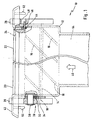
- the air nozzle 10 has a nozzle body 12 in which one Lamellar roller 14 with sloping slats 16 on one Pivot axis 18 is mounted.
- a slat bank 20 with individual slats 22 is supported, each slat on a pivot axis 24 also in the nozzle body 12 is supported.
- the pivot axes 24 and 18 extend essentially parallel to each other.
- Adjustment wheels are provided at their ends, namely an adjustment wheel 26 for the lamellar roller 14 and a setting wheel 28 for the Slat bench 20.
- the adjusting wheel 26 is via a gear 30 with the lamella roller 14 connected.
- the gear 30 has a larger gear 32 and a smaller gear 34 which mesh with each other and whose diameter is the ratio between the Setting wheel 26 and the lamella 14 determined.
- the gear ratio about 3: 1, so that pivoting of the setting wheel 26 a pivoting of the lamella roller 14 by 360 ° by 120 ° corresponds. It is preferred to adjust the pivoting path to provide the setting wheel with 60 °, the middle position of the Adjusting wheel 26 then the central position of the slats 16 of the slat roller mellar roller 14 corresponds to the position in which the fins 16 compared to the position shown in Fig. 1 by 90 ° extend pivoted and allow free air passage. In the position pivoted by 30 ° with respect to this middle position Position, the slats 16 extend through 90 ° pivoted, for example fully to the right, as is shown in FIG. 1 is shown, and in the pivoted by 30 ° in the other direction Position of the adjusting wheel 26 in the opposite Direction so that the air flow 40 that the air nozzle 10th passes, is fully distracted to the left.
- the slat bench 20 consists of the same slats 22.
- the slats 22 are on uniformly spaced pivot axes 24 stored and taken together via a pivot member 44, which is pivotally mounted on driver pin 46 is how it is known per se.
- One of the driver pins 46 passes through both the wall of the nozzle body 12 and at least partially the setting wheel 28 and is there in a corresponding Driving recess 48 performed.
- the design the driver pin 46 and the driving recess 48 is off Fig. 2 can be seen better.
- the nozzle body has 12 locking pins projecting rearward from its front surface 42 50 and 52, which are meant to be the whole Air nozzle 10 at a corresponding recess in the body panel or snap the dashboard into place.
- a butterfly valve 54 which over a suitable actuator also from the front surface 42 of the Air nozzle 10 should be adjustable. This butterfly valve should only be assembled when it is desired, for what purpose the nozzle body has prepared bearing recesses having.
- slats extend 22 side by side, in accordance with a curvature of the front surface 42 of the nozzle body 12. As can be seen, takes place the pivoting of the slats 22 over an angle of something more than 90 ° using the left most Lamella, which has the driver pin 46.
- the setting wheel 28 has the matching driving recess 48, and one corresponding arch recess 56 is provided in the wall, which a movement of the driver pin 46 in the desired Way allowed.
- the Swivel member 44 can be seen more clearly, the at least two Driver pin 46 is snapped and recesses for the Carrying the driver pin 46 of the other slats 22 has.
- Air nozzle are easily possible without the frame of the Leaving invention.
- the farthest the lamella arranged on the left for example that of the one slat further to the right to choose their spacing of an axis 58 of the setting wheel is slightly less, so that another for the same path of movement of the slats Swiveling the setting wheel is required.
- the corresponding driving recesses 48 and 56 can be adapted to the requirements can.
- the slats 24 can also be used in accordance with others Storage can be pivoted beyond the 90 ° position if this is desired.
- the maximum swivel position - Based on that shown in the drawing of FIG. 2 Location - 140 ° or even 160 ° if necessary, so that the air flow in the illustration of FIG. 2 also after could be in the top right.
Landscapes
- Physics & Mathematics (AREA)
- Thermal Sciences (AREA)
- Engineering & Computer Science (AREA)
- Mechanical Engineering (AREA)
- Air-Flow Control Members (AREA)
Description
- Fig. 1
- eine schematische, teils aufgebrochene Ansicht einer erfindungsgemäßen Luftdüse in einer Ausführungsform; und
- Fig. 2
- eine ebenfalls schematische Seitenansicht der Luftdüse gemäß Fig. 1.
Claims (17)
- Luftdüse, insbesondere für den Einsatz in Fahrzeugen, mit einer Lamellenbank (20) zur Richtungsumlenkung des aus der Luftdüse (10) austretenden Luftstroms, die an einem Düsenkörper (12) gelagert ist und sich im wesentlichen parallel zueinander erstreckende Lamellen (22) hat, und mit einer an dem Düsenkörper (12) gelagerten Lamellenwalze (14), die um eine Schwenkachse (18) mittels eines Walzen-Stellrads (26) verschwenkbar ist und die zur Schwenkachse (18) schrägstehende Lamellen (16) hat,
dadurch gekennzeichnet,
daß die Lamellen (22) der Lamellenbank (20) miteinander schwenkbeweglich um Schwenkachsen (24) herum verschwenkbar sind, wobei sich die Schwenkachse (18) der Lamellenwalze im wesentlichen parallel zu den Schwenkachsen (24) der Lamellen (22) der Lamellenbank (20) erstreckt, und
daß das Walzen-Stellrad (26) über ein untersetzendes Getriebe (30) mit der Lamellenwalze (14) gekoppelt ist. - Luftdüse nach Anspruch 1, dadurch gekennzeichnet, daß in dem Düsenkörper (10) an einander gegenüberliegenden Enden Stellräder (26, 28) für das Verschwenken der Lamellenwalze (14) sowie der Lamellenbank (20) gelagert sind.
- Luftdüse nach einem der vorhergehenden Ansprüche, dadurch gekennzeichnet, daß die Schwenkachsen (24) der Lamellen (22) der Lamellenbank (20) im Bereich der Vorderfläche (42) des Düsenkörpers (12), insbesondere eine vorgewölbte Vorderfläche aufspannend, angeordnet sind.
- Luftdüse nach einem der vorhergehenden Ansprüche, dadurch gekennzeichnet, daß die Lamellen (22) sich einseitig von ihrer Schwenkachse (24) weg erstrecken.
- Luftdüse nach einem der vorhergehenden Ansprüche, dadurch gekennzeichnet, daß das Walzen-Stellrad (26) in einer Vorderfläche (42) des Düsenkörpers (12) versenkt gelagert ist und daß das Getriebe (30) eine Untersetzung dergestalt aufweist, daß ein Verschwenken des Walzen-Stellrads (26) um einen in der Vorderfläche (42) des Düsenkörpers (12) freiliegenden Winkel im wesentlichen einer Verschwenkung der Lamellenwalze (14) um 180° entspricht.
- Luftdüse nach einem der vorhergehenden Ansprüche, dadurch gekennzeichnet, daß ein Stellrad (28) für die Lamellenbank (20) eine Mitnahmeausnehmung (48) aufweist, die an einem von der Schwenkachse (24) einer Lamelle (22) beabstandeten Bereich der Lamelle (22) angebracht ist und die Lamelle (22), deren Schwenkachse (24) von der Schwenkachse des Lamellenbank-Stellrads (28) beabstandet ist, mitnimmt.
- Luftdüse nach einem der vorhergehenden Ansprüche, dadurch gekennzeichnet, daß die Lamellen (22) der Lamellenbank (20) im wesentlichen gleich ausgebildet sind und eine der Lamellen (22) einen Stellrad-Mitnehmer (46) aufweist.
- Luftdüse nach einem der vorhergehenden Ansprüche, dadurch gekennzeichnet, daß das Lamellen-Stellrad (28) für die Verschwenkung über den maximalen Schwenkbereich der Lamellen (22) über einen Winkel verschwenkbar ist, der dem Winkel des die Vorderfläche (42) des Düsenkörpers (12) durchtretenden freiliegenden Bereichs des Stellrads (28) im wesentlichen entspricht.
- Luftdüse nach einem der vorhergehenden Ansprüche, dadurch gekennzeichnet, daß die Lamellen (22) der Lamellenbank (20) über einen Winkel von etwa 90°, insbesondere mindestens teilweise über einen Winkel von etwas mehr als 90° verschwenkbar sind und die Richtung des Luftaustritts in einer Dimension festlegen und die Lamellenwalze (16) in Abhängigkeit von ihrer Schwenkstellung die Richtung des Luftaustritts in einer weiteren Dimension festlegt.
- Luftdüse nach einem der vorhergehenden Ansprüche, dadurch gekennzeichnet, daß die Lamellen (22) der Lamellenbank (20) über mindestens ein Schwenkglied (44) miteinander im wesentlichen drehfest verbunden sind, das insbesondere entsprechend der Vorwölbung der Lamellen (22), betrachtet in einer Richtung quer zu den Schwenkachsen (24) der Lamellen (22), gewölbt ist.
- Luftdüse nach einem der vorhergehenden Ansprüche, dadurch gekennzeichnet, daß die Luftdüse (10) eine längliche Form aufweist, wobei sich die Lamellen (22) der Lamellenbank (20) und die Lamellenwalze (14) im wesentlichen in Längsrichtung der Düse (10) erstrecken und die Stellräder (26, 28) an den Schmalseiten der Luftdüse (10) angebracht sind, wobei der freie Strömungsquerschnitt der Lamellenbank (20) ein Längen-/Breitenverhältnis von mehr als 2, insbesondere von etwa 100:40 aufweist.
- Luftdüse nach einem der vorhergehenden Ansprüche, dadurch gekennzeichnet, daß hinter der Lamellenwalze (14) eine Absperrklappe (54) an dem Düsenkörper (12) gelagert ist, die über ein Betätigungselement an der Vorderfläche (42) des Düsenkörpers (12) betätigbar ist und mit welcher der Luftstrom der Luftdüse (10) regelbar und insbesondere absperrbar ist.
- Luftdüse nach einem der vorhergehenden Ansprüche, dadurch gekennzeichnet, daß sie modular aufgebaut ist und der Düsenkörper (12) wahlweise mit der Lamellenwalze (16) und/oder einer Absperrklappe (54) bestückbar ist.
- Luftdüse nach einem der vorhergehenden Ansprüche, dadurch gekennzeichnet, daß die Lamellen (22) der Lamellenbank (20) über einen Winkel von 140° verschwenkbar sind, insbesondere von einer geschlossenen 0°-Gradstellung über eine vollständig offene 90°-Stellung bis zur Endstellung.
- Luftdüse nach einem der vorhergehenden Ansprüche, dadurch gekennzeichnet, daß die Untersetzung des Getriebes (30) 3:1 beträgt.
- Luftdüse nach Anspruch 15, dadurch gekennzeichnet, daß das untersetzende Getriebe (30) ein Verschwenken des Walzen-Stellrads (26) von 60° in ein Verschwenken der Lamellen (16) der Lamellenwalze (14) um 180° umsetzt.
- Luftdüse nach einem der vorhergehenden Ansprüche, dadurch gekennzeichnet, daß das Getriebe (30) ein größeres Zahnrad (32) und ein kleineres Zahnrad (34) aufweist, die miteinander kämmen und deren Durchmesser das Übersetzungsverhältnis zwischen dem Walzen-Stellrad (26) und der Lamellenwalze (14) bestimmt.
Applications Claiming Priority (2)
| Application Number | Priority Date | Filing Date | Title |
|---|---|---|---|
| DE19600205 | 1996-01-04 | ||
| DE19600205A DE19600205C2 (de) | 1996-01-04 | 1996-01-04 | Luftdüse |
Publications (3)
| Publication Number | Publication Date |
|---|---|
| EP0782939A2 EP0782939A2 (de) | 1997-07-09 |
| EP0782939A3 EP0782939A3 (de) | 1998-08-19 |
| EP0782939B1 true EP0782939B1 (de) | 2001-03-14 |
Family
ID=7782177
Family Applications (1)
| Application Number | Title | Priority Date | Filing Date |
|---|---|---|---|
| EP97100071A Expired - Lifetime EP0782939B1 (de) | 1996-01-04 | 1997-01-03 | Luftdüse |
Country Status (4)
| Country | Link |
|---|---|
| US (1) | US5820457A (de) |
| EP (1) | EP0782939B1 (de) |
| DE (2) | DE19600205C2 (de) |
| TR (1) | TR199700002A2 (de) |
Families Citing this family (9)
| Publication number | Priority date | Publication date | Assignee | Title |
|---|---|---|---|---|
| FR2766765B1 (fr) | 1997-08-04 | 1999-10-01 | Coutier Moulage Gen Ind | Barillet d'aerateur pour un vehicule automobile |
| DE19857153C1 (de) * | 1998-12-11 | 2000-04-13 | Opel Adam Ag | Luftdüse für Kraftfahrzeuge |
| DE10323522A1 (de) * | 2003-05-24 | 2004-12-09 | Adam Opel Ag | Lüftungsdüse zur Innenraumbelüftung eines Kraftfahrzeuges |
| DE102004003797A1 (de) * | 2004-01-26 | 2005-08-18 | Meiko Maschinenbau Gmbh & Co. Kg | Geschirrspülautomat mit regelbarer Wärmrückgewinnung |
| US6959653B1 (en) * | 2004-04-22 | 2005-11-01 | Alstom Technology Ltd | Fuel nozzle for a fossil fuel fired combustion arrangement |
| DE102008023562B3 (de) * | 2008-05-14 | 2009-08-20 | Webasto Ag | System zum Schließen und Öffnen von Lamellen in einer Belüftungseinrichtung für Kraftfahrzeuge |
| USD788903S1 (en) * | 2014-07-27 | 2017-06-06 | Aurora Konrad G. Schulz Gmbh & Co. Kg | Defrost nozzle |
| US10144269B2 (en) * | 2015-10-28 | 2018-12-04 | Ford Global Technologies, Llc | Dual line register |
| CN117021904A (zh) * | 2023-08-08 | 2023-11-10 | 东风汽车集团股份有限公司 | 一种出风口结构、空调系统及车辆 |
Family Cites Families (17)
| Publication number | Priority date | Publication date | Assignee | Title |
|---|---|---|---|---|
| DE841945C (de) * | 1949-06-25 | 1952-06-19 | Heinrich Nickel O H G | Zuluftgitter fuer Belueftungsanlagen |
| US2894441A (en) * | 1955-09-13 | 1959-07-14 | Gen Motors Corp | Universal air deflector outlet devices |
| GB1177390A (en) * | 1967-09-26 | 1970-01-14 | Clear Hooters Ltd | Directional Air-discharging Nozzle for a Heating or Ventilating System |
| GB1320695A (en) * | 1969-06-27 | 1973-06-20 | Creators Ltd | Controlled flow air outlet device for ventilating or heating systems |
| GB1347978A (en) * | 1970-11-07 | 1974-02-27 | Clear Hooters Ltd | Directional air-discharging nozzle for a heating or ventilating system |
| US3701311A (en) * | 1970-12-07 | 1972-10-31 | Cary Products Inc | Louver construction |
| US3683787A (en) * | 1970-12-07 | 1972-08-15 | Arthur P Cary | Air flow system with full control elliptical vane louvers |
| GB1452270A (en) * | 1972-10-10 | 1976-10-13 | Clear Hooters Ltd | Air-discharging nozzle for a heating or ventilating system |
| US3823875A (en) * | 1973-08-24 | 1974-07-16 | T Bauer | Burner nozzle tip for pulverized coal and method for its production |
| DE2628663C3 (de) * | 1976-06-25 | 1979-05-17 | Bayerische Motoren Werke Ag, 8000 Muenchen | Belüftungsvorrichtung für den Innenraum von Kraftfahrzeugen |
| JPS584256B2 (ja) * | 1979-09-13 | 1983-01-25 | 三菱電機株式会社 | 空調機用風向制御装置 |
| US5080002A (en) * | 1989-09-12 | 1992-01-14 | Siemens Aktiengesellschaft | Outlet nozzle for ventilation or air-conditioning systems |
| NL9001436A (nl) * | 1990-06-22 | 1992-01-16 | Hubertus Gerardus Jacobus Peet | Ventilatieluik. |
| US5188561A (en) * | 1991-08-01 | 1993-02-23 | Nissim Nissimoff | Air conditioning grill |
| WO1993023261A1 (de) * | 1992-05-08 | 1993-11-25 | Dr. Franz Schneider Gmbh | Luftdüse für belüftungs- oder klimaanlagen |
| US5364303A (en) * | 1993-07-09 | 1994-11-15 | Summit Polymers, Inc. | Air vent adjustable vanes for controlling air flow direction |
| US5573458A (en) * | 1996-03-06 | 1996-11-12 | Chu; Chia-Chuan | Air-conditioner outlet |
-
1996
- 1996-01-04 DE DE19600205A patent/DE19600205C2/de not_active Expired - Fee Related
-
1997
- 1997-01-03 EP EP97100071A patent/EP0782939B1/de not_active Expired - Lifetime
- 1997-01-03 DE DE59703120T patent/DE59703120D1/de not_active Expired - Fee Related
- 1997-01-03 TR TR97/00002A patent/TR199700002A2/xx unknown
- 1997-01-03 US US08/778,792 patent/US5820457A/en not_active Expired - Fee Related
Also Published As
| Publication number | Publication date |
|---|---|
| TR199700002A3 (de) | 2001-07-23 |
| DE19600205A1 (de) | 1997-07-10 |
| TR199700002A2 (tr) | 1997-07-21 |
| DE59703120D1 (de) | 2001-04-19 |
| EP0782939A2 (de) | 1997-07-09 |
| DE19600205C2 (de) | 2003-06-26 |
| US5820457A (en) | 1998-10-13 |
| EP0782939A3 (de) | 1998-08-19 |
Similar Documents
| Publication | Publication Date | Title |
|---|---|---|
| DE102004048038B4 (de) | Verschließbare Kraftfahrzeug-Kühlergrillanordnung | |
| DE19943822B4 (de) | Strömungsleitanordnung, insbesondere Ausströmgrill für Lüftungs- und Klimaanlagen von Kraftfahrzeugen | |
| EP3027443B1 (de) | Luftleitelement | |
| DE202011050032U1 (de) | Drosseleinrichtung für den Luftdurchsatz durch einen Luftdurchlass | |
| EP1497147B1 (de) | Bel ftungseinrichtung | |
| EP3321113B1 (de) | Luftausströmer | |
| EP1270286B1 (de) | Luftleitvorrichtung, insbesondere eines Fahrzeugs | |
| EP2266824B1 (de) | Luftdurchsatzelement | |
| DE19600205C2 (de) | Luftdüse | |
| DE19626937C2 (de) | Vorrichtung zur Geräuschminderung an einer Schiebedachöffnung eines Fahrzeugs | |
| DE102010023528B4 (de) | Luftausströmvorrichtung für ein Fahrzeug | |
| DE60016116T2 (de) | Lüftungsgitter, insbesondere für Kraftfahrzeuge | |
| WO1998057815A1 (de) | Luftstromregulierungsdüse zur belüftung eines kraftfahrzeuginnenraumes | |
| EP0283863A1 (de) | Höhen- und neigungsverstellbare Kopfstütze für Kraftfahrzeugsitze | |
| DE102005058972B4 (de) | Luftdüse mit Horizontal- und/oder Vertikallamellen | |
| EP1793180B1 (de) | Belüftungsdüse mit Horizontal- und/oder Vertikallamellen | |
| DE19816013A1 (de) | Luftstromverteiler für einen Kraftfahrzeuginnenraum | |
| EP3790749B1 (de) | Ausströmer für ein fahrzeug | |
| DE102005055700B3 (de) | Ausströmdüse für den Fahrgastraum eines Kraftfahrzeuges | |
| DE102015213524B4 (de) | Vorrichtung zum Steuern von Durchströmöffnungen in Lüftungsgittern von Kraftfahrzeugen | |
| DE4100435C2 (de) | ||
| DE2721751B2 (de) | Doppelwandige Seitentür eines Kraftfahrzeugs mit einem absenkbaren Türfenster | |
| AT527742B1 (de) | Witterungsschutzanlage | |
| DE102010044596A1 (de) | Rollladenpanzer | |
| DE102017122039A1 (de) | Luftausströmer für ein Fahrzeug |
Legal Events
| Date | Code | Title | Description |
|---|---|---|---|
| PUAI | Public reference made under article 153(3) epc to a published international application that has entered the european phase |
Free format text: ORIGINAL CODE: 0009012 |
|
| AK | Designated contracting states |
Kind code of ref document: A2 Designated state(s): DE FR GB IT |
|
| PUAL | Search report despatched |
Free format text: ORIGINAL CODE: 0009013 |
|
| AK | Designated contracting states |
Kind code of ref document: A3 Designated state(s): DE FR GB IT |
|
| 17P | Request for examination filed |
Effective date: 19990215 |
|
| 17Q | First examination report despatched |
Effective date: 19990319 |
|
| GRAG | Despatch of communication of intention to grant |
Free format text: ORIGINAL CODE: EPIDOS AGRA |
|
| GRAG | Despatch of communication of intention to grant |
Free format text: ORIGINAL CODE: EPIDOS AGRA |
|
| GRAH | Despatch of communication of intention to grant a patent |
Free format text: ORIGINAL CODE: EPIDOS IGRA |
|
| GRAH | Despatch of communication of intention to grant a patent |
Free format text: ORIGINAL CODE: EPIDOS IGRA |
|
| GRAA | (expected) grant |
Free format text: ORIGINAL CODE: 0009210 |
|
| AK | Designated contracting states |
Kind code of ref document: B1 Designated state(s): DE FR GB IT |
|
| REF | Corresponds to: |
Ref document number: 59703120 Country of ref document: DE Date of ref document: 20010419 |
|
| ITF | It: translation for a ep patent filed | ||
| ET | Fr: translation filed | ||
| GBT | Gb: translation of ep patent filed (gb section 77(6)(a)/1977) |
Effective date: 20010619 |
|
| REG | Reference to a national code |
Ref country code: GB Ref legal event code: IF02 |
|
| PLBE | No opposition filed within time limit |
Free format text: ORIGINAL CODE: 0009261 |
|
| STAA | Information on the status of an ep patent application or granted ep patent |
Free format text: STATUS: NO OPPOSITION FILED WITHIN TIME LIMIT |
|
| 26N | No opposition filed | ||
| PGFP | Annual fee paid to national office [announced via postgrant information from national office to epo] |
Ref country code: DE Payment date: 20021108 Year of fee payment: 7 |
|
| PGFP | Annual fee paid to national office [announced via postgrant information from national office to epo] |
Ref country code: GB Payment date: 20021227 Year of fee payment: 7 |
|
| PGFP | Annual fee paid to national office [announced via postgrant information from national office to epo] |
Ref country code: FR Payment date: 20030127 Year of fee payment: 7 |
|
| PG25 | Lapsed in a contracting state [announced via postgrant information from national office to epo] |
Ref country code: GB Free format text: LAPSE BECAUSE OF NON-PAYMENT OF DUE FEES Effective date: 20040103 |
|
| PG25 | Lapsed in a contracting state [announced via postgrant information from national office to epo] |
Ref country code: DE Free format text: LAPSE BECAUSE OF NON-PAYMENT OF DUE FEES Effective date: 20040803 |
|
| GBPC | Gb: european patent ceased through non-payment of renewal fee |
Effective date: 20040103 |
|
| PG25 | Lapsed in a contracting state [announced via postgrant information from national office to epo] |
Ref country code: FR Free format text: LAPSE BECAUSE OF NON-PAYMENT OF DUE FEES Effective date: 20040930 |
|
| REG | Reference to a national code |
Ref country code: FR Ref legal event code: ST |
|
| PG25 | Lapsed in a contracting state [announced via postgrant information from national office to epo] |
Ref country code: IT Free format text: LAPSE BECAUSE OF NON-PAYMENT OF DUE FEES;WARNING: LAPSES OF ITALIAN PATENTS WITH EFFECTIVE DATE BEFORE 2007 MAY HAVE OCCURRED AT ANY TIME BEFORE 2007. THE CORRECT EFFECTIVE DATE MAY BE DIFFERENT FROM THE ONE RECORDED. Effective date: 20050103 |