EP0781908A2 - Turboladerausbau - Google Patents
Turboladerausbau Download PDFInfo
- Publication number
- EP0781908A2 EP0781908A2 EP96120837A EP96120837A EP0781908A2 EP 0781908 A2 EP0781908 A2 EP 0781908A2 EP 96120837 A EP96120837 A EP 96120837A EP 96120837 A EP96120837 A EP 96120837A EP 0781908 A2 EP0781908 A2 EP 0781908A2
- Authority
- EP
- European Patent Office
- Prior art keywords
- bearing
- housing
- turbocharger
- rotor shaft
- turbine
- Prior art date
- Legal status (The legal status is an assumption and is not a legal conclusion. Google has not performed a legal analysis and makes no representation as to the accuracy of the status listed.)
- Withdrawn
Links
- 238000010276 construction Methods 0.000 title description 2
- 238000004519 manufacturing process Methods 0.000 claims description 11
- 238000000034 method Methods 0.000 claims description 8
- 238000000465 moulding Methods 0.000 claims description 3
- 239000011810 insulating material Substances 0.000 claims description 2
- 230000005855 radiation Effects 0.000 claims description 2
- XLYOFNOQVPJJNP-UHFFFAOYSA-N water Substances O XLYOFNOQVPJJNP-UHFFFAOYSA-N 0.000 claims description 2
- 239000012530 fluid Substances 0.000 claims 2
- 239000012212 insulator Substances 0.000 abstract description 3
- 238000005461 lubrication Methods 0.000 description 29
- 238000007667 floating Methods 0.000 description 19
- 238000009434 installation Methods 0.000 description 7
- 239000000498 cooling water Substances 0.000 description 6
- 238000009413 insulation Methods 0.000 description 5
- 238000005266 casting Methods 0.000 description 3
- 230000015572 biosynthetic process Effects 0.000 description 2
- 239000012809 cooling fluid Substances 0.000 description 2
- 230000006866 deterioration Effects 0.000 description 2
- 238000003780 insertion Methods 0.000 description 2
- 230000037431 insertion Effects 0.000 description 2
- 238000003754 machining Methods 0.000 description 2
- 230000013011 mating Effects 0.000 description 2
- 230000003685 thermal hair damage Effects 0.000 description 2
- 238000005520 cutting process Methods 0.000 description 1
- 239000011796 hollow space material Substances 0.000 description 1
- 238000012986 modification Methods 0.000 description 1
- 230000004048 modification Effects 0.000 description 1
Images


Classifications
-
- F—MECHANICAL ENGINEERING; LIGHTING; HEATING; WEAPONS; BLASTING
- F01—MACHINES OR ENGINES IN GENERAL; ENGINE PLANTS IN GENERAL; STEAM ENGINES
- F01D—NON-POSITIVE DISPLACEMENT MACHINES OR ENGINES, e.g. STEAM TURBINES
- F01D25/00—Component parts, details, or accessories, not provided for in, or of interest apart from, other groups
- F01D25/16—Arrangement of bearings; Supporting or mounting bearings in casings
- F01D25/166—Sliding contact bearing
-
- F—MECHANICAL ENGINEERING; LIGHTING; HEATING; WEAPONS; BLASTING
- F16—ENGINEERING ELEMENTS AND UNITS; GENERAL MEASURES FOR PRODUCING AND MAINTAINING EFFECTIVE FUNCTIONING OF MACHINES OR INSTALLATIONS; THERMAL INSULATION IN GENERAL
- F16C—SHAFTS; FLEXIBLE SHAFTS; ELEMENTS OR CRANKSHAFT MECHANISMS; ROTARY BODIES OTHER THAN GEARING ELEMENTS; BEARINGS
- F16C17/00—Sliding-contact bearings for exclusively rotary movement
- F16C17/10—Sliding-contact bearings for exclusively rotary movement for both radial and axial load
-
- F—MECHANICAL ENGINEERING; LIGHTING; HEATING; WEAPONS; BLASTING
- F16—ENGINEERING ELEMENTS AND UNITS; GENERAL MEASURES FOR PRODUCING AND MAINTAINING EFFECTIVE FUNCTIONING OF MACHINES OR INSTALLATIONS; THERMAL INSULATION IN GENERAL
- F16C—SHAFTS; FLEXIBLE SHAFTS; ELEMENTS OR CRANKSHAFT MECHANISMS; ROTARY BODIES OTHER THAN GEARING ELEMENTS; BEARINGS
- F16C27/00—Elastic or yielding bearings or bearing supports, for exclusively rotary movement
- F16C27/02—Sliding-contact bearings
-
- F—MECHANICAL ENGINEERING; LIGHTING; HEATING; WEAPONS; BLASTING
- F16—ENGINEERING ELEMENTS AND UNITS; GENERAL MEASURES FOR PRODUCING AND MAINTAINING EFFECTIVE FUNCTIONING OF MACHINES OR INSTALLATIONS; THERMAL INSULATION IN GENERAL
- F16C—SHAFTS; FLEXIBLE SHAFTS; ELEMENTS OR CRANKSHAFT MECHANISMS; ROTARY BODIES OTHER THAN GEARING ELEMENTS; BEARINGS
- F16C35/00—Rigid support of bearing units; Housings, e.g. caps, covers
- F16C35/02—Rigid support of bearing units; Housings, e.g. caps, covers in the case of sliding-contact bearings
-
- F—MECHANICAL ENGINEERING; LIGHTING; HEATING; WEAPONS; BLASTING
- F05—INDEXING SCHEMES RELATING TO ENGINES OR PUMPS IN VARIOUS SUBCLASSES OF CLASSES F01-F04
- F05D—INDEXING SCHEME FOR ASPECTS RELATING TO NON-POSITIVE-DISPLACEMENT MACHINES OR ENGINES, GAS-TURBINES OR JET-PROPULSION PLANTS
- F05D2220/00—Application
- F05D2220/40—Application in turbochargers
-
- F—MECHANICAL ENGINEERING; LIGHTING; HEATING; WEAPONS; BLASTING
- F16—ENGINEERING ELEMENTS AND UNITS; GENERAL MEASURES FOR PRODUCING AND MAINTAINING EFFECTIVE FUNCTIONING OF MACHINES OR INSTALLATIONS; THERMAL INSULATION IN GENERAL
- F16C—SHAFTS; FLEXIBLE SHAFTS; ELEMENTS OR CRANKSHAFT MECHANISMS; ROTARY BODIES OTHER THAN GEARING ELEMENTS; BEARINGS
- F16C2360/00—Engines or pumps
- F16C2360/23—Gas turbine engines
- F16C2360/24—Turbochargers
Definitions
- the present invention relates to a turbocharger and particularly to an improvement of a housing for a turbocharger, and it further relates to a method of manufacturing the turbocharger.
- Turbochargers and housings therefor are known in the art.
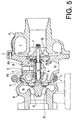
- a conventional turbocharger housing is illustrated in Figure 5 of the accompanying drawings in cross section.
- This typical turbocharger housing includes a turbine housing b for housing a turbine rotor a , a compressor housing d for housing a compressor impeller c and a bearing housing g for housing a group of bearings f for a rotor shaft e .
- the rotor shaft e connects the turbine rotor a with the compressor impeller c .
- the bearing housing g is positioned between the turbine and compressor housings b and d .
- the turbine housing b and bearing housing g are aligned by a pin h provided at their interface k . Outer peripheries of these two housings b and g at the interface k are clamped by a clamp i .
- the bearing and compressor housings g and d are coupled by bolts j .
- the set of bearings f includes a journal bearing f1 and a thrust bearing f2.
- the journal bearing f1 fitted in a shaft bore formed in the bearing housing g near an end of the shaft bore on the turbine housing side and the thrust bearing f2 mounted at the opposite end of the shaft bore.
- the journal bearing f1 is a cylindrical full float bearing which bears a radial force.
- the thrust bearing f2 includes a first ring-shaped member fa fixed on the rotor shaft e and a second member fb engaged with the first member fa and secured to the bearing housing g .
- the thrust bearing f2 bears a thrust force.
- This type of turbocharger housing includes three housings b , g and d and two separate bearings f1 and f2 inside the bearing housing g so that it needs a lot of parts and a lot of assembling processes.
- a straight, narrow and long shaft bore should be accurately formed in the bearing housing g and installation of the bearings f1 and f2 should be carried out with great care.
- the bearings f1 and f2 should be kept off dusts or the like: it should be stored and maintained in a clean atmosphere before and during installation. Therefore, a lot of labor, time and care is required in a delicate bearing installation operation.
- a plurality of narrow bores m is also required for delivery of a lubrication oil to the bearings f1 and f2 from a lubrication oil entrance t .
- connection between the left and center housings b and g and that between the center and right housings g and d do not require high accuracy.
- connection between the housings b , g and d and the installation of the bearings f1 and f2 into the bearing housing g are performed on a single manufacturing line.
- a gas may leak from the interface k between the turbine housing b and bearing housing g .
- the lubrication oil fed from the oil inlet or entrance t flows downward in the bores m , lubricates the bearings f1 and f2, drops to an exit n opened at a lower portion of the bearing housing g and ultimately returns to an engine (not shown) via a drain oil line (not shown).
- r designates a diffuser formed in the compressor housing d and s designates a nozzle formed in the turbine housing b .
- a similar housing structure for a turbocharger is disclosed in Japanese Patent Application, Laid-Open Publication No. 7-139363.
- One object of the present invention is to provide a housing for a turbocharger which does not have the above described problems.
- a turbine housing for a turbine rotor and a bearing housing for rotation shaft bearings are united to a one piece part. This reduces the number of parts and the number of manufacturing processes and in turn results in easier assembling. Further, a gas leakage from connection between the turbine and bearing housings is completely prevented.
- a plurality of rotation shaft bearings may be manufactured as a single unit on a separate and special manufacturing line in a clean atmosphere and such a bearing unit may be installed into the above mentioned one piece housing. Since the bearings are assembled on a separate manufacturing line in a clean atmosphere, the cleanness and high accuracy required to the bearing installation are attained. The bearing unit which is previously prepared is then carried to a manufacturing line on which the one piece housing is moved, and the bearing unit is incorporated into the one piece housing. This series of processes is simpler than the conventional one.
- a heat insulation means may be provided behind the turbine rotor in the one piece housing for preventing transfer of a substantial part of heat to the bearing unit from the turbine rotor.
- the turbine rotor is subjected to a very hot exhaust gas and heated to a considerably high temperature.
- the heat insulator means suppresses temperature elevation of the bearing unit and prevents the thermal damages/deteriorations otherwise caused by the heat transmitted from the turbine rotor.
- the one piece housing may have an exhaust gas opening which also allows insertion of the turbine rotor into the one piece housing. This facilitates the assembling of the turbocharger.
- a turbocharger housing of this embodiment includes a one piece housing 1 which is comprised of a turbine housing portion 1a and a bearing housing portion 1b.
- the turbine housing portion 1a houses a turbine rotor 2 and the bearing housing portion 1b houses a bearing unit 3.
- the turbine housing portion 1a has an exhaust gas inlet opening 4 directed in a radial direction of the turbocharger and an exhaust gas exit opening 5 directed in an axial direction.
- An exhaust gas enters the turbine housing portion 1a from the inlet opening 4, drives the turbine rotor 2 and flows to the exit opening 5.
- the bearing housing portion 1b has a lubrication oil inlet 6 directed upward and an exit 7 directed downward.
- a lubrication oil is fed into the bearing housing portion 1b from the lubrication entrance 6 and lubricates the bearing unit 3 before it is discharged from the lubrication oil exit 7.
- the lubrication oil expelled from the exit 7 is delivered to an engine (not shown) through a drain oil line (not shown).
- the bearing unit 3 journally supports a rotation shaft 9 which connects the turbine rotor 2 with a compressor impeller 8 (will be described later in detail).
- the rotation shaft 9 extends from the turbine rotor 2.
- the rotation shaft 9 and turbine rotor 2 are manufactured as one unit.
- the one piece housing 1 also has an annular bore 10 formed inside itself behind the turbine rotor 2 for passage of a cooling water.
- the cooling water bore 10 has an entrance and an exit (not shown).
- the cooling water flows in the bore 10 and absorbs heat of the turbine rotor 2 and turbine housing portion 1a heated by the very hot exhaust gas respectively. Consequently, most of the heat is not transferred to the bearing unit 3 from the turbine rotor 2 and turbine housing portion 1a.
- the cooling water and cooling water passage 10 form in combination a heat insulation means. It is of course that a lubrication oil may be used instead of the cooling water.
- the heat insulation means is not limited to the combination of cooling fluid (water or oil) and its passage.
- an air or space may be used as a heat insulator.
- the one piece housing 1 may be scraped out at an area 1c between the turbine housing portion 1a and bearing housing portion 1b to form a heat insulating space 11 between the turbine housing portion 1a and bearing housing portion 1b.
- the heat insulation space 11 may be filled with a heat insulating material (not shown) and/or a heat radiator such as radiation fins (not shown) may be provided on a back 1d of the turbine housing portion 1a.
- the bearing housing portion 1b of the one piece housing 1 has an opening 12 directed in an opposite direction to the exhaust gas exit opening 5 of the turbine housing portion 1a.
- the bearing unit 3 is inserted into the one piece housing 1 from the opening 12.
- the bearing unit 3 includes a generally cylindrical bearing box 13 and a cylindrical semi floating bearing 14 fitted in the bearing box 13.
- the bearing box 13 and semi floating bearing 14 have the same length.
- the positioning and fixing of the semi floating bearing 14 relative to the bearing box 13 is determined and achieved by a thrust pin 15.
- the rotation shaft 9 rotatably extends through the semi floating bearing 14.
- a clearance is formed between the semi floating bearing 14 and bearing box 13 to form a lubrication oil film.
- a clearance is formed between the semi floating bearing 14 and rotation shaft 9 for formation of another lubrication oil film. Therefore, the rotation shaft 9 and bearing 14 are maintained in a floating condition by the lubrication oil, respectively.
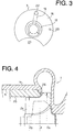
- the bearing box 13 also has a sword guard-like flange member 16 which extends radially outward. The shape of this member 16 as viewed in the longitudinal direction of the rotation shaft 9 is shown in Figure 3.
- a lubrication oil passage 18 is formed in the flange member 16 such that it generally extends upward in a perpendicular direction relative to the rotation shaft 9.
- the lubrication oil passage 18 is bent 90 degrees at its upper end portion 22 in a horizontal direction so that an upper end of the oil passage 18 is communicated with the lower end of the lubrication oil inlet 6.
- the lubrication oil inlet 6 is drilled downwardly from an outer surface of the one piece housing 1 in a perpendicular direction relative to the rotation shaft 9. As understood from Figure 3, the upper end of the oil passage 18 opens in a lateral surface of the flange member 16 at 22.
- the lower end of the oil passage 18 opens in an inner surface of the bearing box 13 so that the oil passage 18 is communicated with the space between the bearing box 13 and semi floating bearing 14.
- a perpendicular through hole 19 is also formed in the semi floating bearing 14.
- This bore 19 partly overlaps the lubrication oil passage 18 so that its upper end communicates with the lower end of the oil passage 18.
- a lower end of the bore 19 connects to the space between the semi floating bearing 14 and rotation shaft 9. Therefore, the lubrication oil introduced into the oil entrance 6 of the one piece housing 1 flows into the lubrication oil passage 18 bored in the flange member 16 and reaches the space between the bearing box 13 and semi floating bearing 14.
- the lubrication oil also flows into the bore 19 of the semi floating bearing 14 and reaches the space between the semi floating bearing 14 and rotation shaft 9.
- the lubrication oil flows out of the bearing unit 3 from ends of the semi floating bearing 14 and bearing box 13 respectively and is ultimately discharged from the one piece housing 1 from the lubrication oil exit 7.
- the sword guard-like flange 16 of the bearing unit 3 has an arcuate cut out 20 at its lower portion. As understood from Figure 1, this cut out portion 20 is necessary to allow the lubrication oil to flow downward from the right side of the flange 16. If the flange 16 was a complete circle as indicated by the double-dot line in Figure 1 below the pin 15, the right space 21 of the flange 16 would be closed by the flange 16 and the lubrication oil would be confined.
- numeral 24 designates a spring pin which engages into a through hole 23 shown in Figure 3. The spring pin 24 and the mating hole 23 determine in combination the position of the flange 16.
- the turbine rotor 2 is a mixed flow turbine and has a uniform diameter D in the longitudinal direction of the rotation shaft 9.
- the diameter D is defined by a plurality of turbine blades 2a of the turbine rotor 2.
- the diameter of the exhaust gas exit 5 is determined such that the insertion of the turbine rotor 2 from the exhaust gas exit 5 is possible.
- the diameter of the turbine rotor varies (or increases) in the longitudinal direction of the rotation shaft as shown in Figure 5. Therefore, it is not feasible to insert the turbine rotor a from the exhaust gas exit.
- the exhaust gas exit 5 of the one piece housing 1 is formed to have a diameter X which conforms to the maximum diameter Dx.
- a special liner 25 is inserted from the exhaust gas exit 5.
- the liner 25 is shaped to accommodate to an outer configuration of the turbine rotor 2X and serves as an exducer.
- the exhaust gas exit 5 has an annular stepwise portion 26 at its deepest position to determine the position of the liner 25. In this manner, the turbine rotor 2 is incorporated into the one piece housing 1.
- the double-dot line indicates the configuration of a mixed flow turbine rotor which has a non-uniform diameter.
- the exhaust gas exit 5 also has a diameter X which can cope with the largest diameter Dx of the turbine rotor, and the liner 25 is attached later to almost fill up the clearance between the exhaust gas exit 5 and the turbine rotor or to leave a necessary clearance.
- the rotor shaft 9 extending from the turbine rotor 2 is inserted into the semi floating bearing 14 of the bearing unit 3 as illustrated in Figure 1 such that it penetrates the bearing unit 3.
- a thrust bearing 28 is attached to a stepwise portion 27 of the rotor shaft 9.
- the rotor shaft 9 has a length having a reduced diameter extending from the stepwise portion 27.
- the stepwise portion 27 is coplanar to the end face of the semi floating bearing 14.
- a thrust force applied to the rotor shaft 9 is born by the thrust bearing 28 and/or an enlarged portion 29 of the rotor shaft 9 formed at an end opposite the thrust bearing 28 as the thrust bearing 28 and enlarged portion 29 abut the end faces of the semi floating bearing 14.
- a seal plate 30 is attached to the main housing 1 by bolts 31 to close the opening 12 of the main housing 1.
- the seal plate 30 seals the one piece housing 1 to prevent leakage of the lubrication oil from the opening 12, and also clamps the flange 16 of the bearing unit 3 between the stepwise portion 17 of the housing 1 and itself by its leg portion which is fitted in the opening 12.
- the seal plate 30 has a recess 32 at its inner center and houses an approximate right third of the bearing unit 3.
- the seal plate 30 also has a center through hole in which the thrust bearing 38 is partly fitted.
- the center hole has a generally truncated conical shape and the thrust bearing 28 has a mating conical shape so that the thrust bearing 28 is firmly held by the seal plate 30.
- the rotor shaft 9 extends through this center hole.
- a compressor impeller 8 is mounted on a free end of the rotor shaft 9 by a nut 33. Then, a compressor casing 34 is attached to the main housing 1 by bolts 35 to cover the compressor impeller 8 and to complete the assembling.
- the turbocharger housing having the above described construction has a one piece main housing 1 which is comprised of the turbine housing portion and bearing housing portion so that a step of connecting the turbine housing with the bearing housing and parts necessary for this step, which are required in a conventional assembling method, are dispensed with. Therefore, the number of parts necessary for the assembling the turbocharger is reduced and the assembling process is simplified. This facilitates automatization of the turbocharger. Moreover, a problem of gas leakage from the interface between the turbine housing and bearing housing never occurs.
- the bearing unit 3 is previously prepared on a separate manufacturing line, carried to a main manufacturing line (i.e., turbo-charger assembling line) and is inserted into the main housing 1 from the opening 12.
- the bearing unit 3 should have high accuracy and cleanness so that it is manufactured to meet such requirements on a separate line.
- the bearing unit 3 is simply inserted into the main housing 1 so that the assembling step on this manufacturing line is easy.
- a delicate bearing installation step is not carried out on the turbocharger assembling line. Consequently, the turbocharger can be manufactured at a lower cost and with high precision.
- the turbocharger can be manufactured with a low cost.
- a core used for casting (or molding) the one piece housing 1 can have a simple shape since the inner space from the right opening 12 has a simple shape. Therefore, the casting can be carried out easily and inexpensively.
- the heat insulating means i.e., the cooling fluid passage 10 ( Figure 1) or heat insulation space 11 ( Figure 2)
- Figure 1 the cooling fluid passage 10
- Figure 2 heat insulation space 11
- the bearing unit 3 Since the bearing unit 3 is supported or suspended in the large hollow space defined between the large recess formed by the main housing 1 on the opening 12 side and the inner recess of the compressor casing 34 and it only contacts the main housing 1 at its sword guard-like flange 16, a heat transfer route to the bearing unit 3 from the turbine rotor 2 and turbine housing portion 1a is limited and elongated as compared with the conventional arrangement shown in Figure 5. The heat is transmitted to the bearing unit 3 through the flange 16 only. Therefore, the temperature rise of the bearing unit 3 due to heat transfer from the neighboring components is suppressed.
- This pressure difference causes the lubrication oil in the bearing housing g to leak to the turbine rotor a and/or compressor impeller c through a clearance p between the turbine rotor bearing and bearing housing g and/or a clearance g between the rotor shaft e bearing and the compressor impeller c .
- there is no possibility of oil leakage since a large free space is created around the bearing unit 3 as illustrated in Figure 3 and this large free space provides better pressure balance in the bearing housing.
- bearing unit 3 is not limited to the one having a semi floating bearing 14.
- a full floating type bearing set such as that shown in Figure 5 including a journal bearing f1 and thrust bearing f2 may be employed as far as these bearings f1 and f2 can be manufactured as a single bearing unit on a separate manufacturing line.
Landscapes
- Engineering & Computer Science (AREA)
- General Engineering & Computer Science (AREA)
- Mechanical Engineering (AREA)
- Supercharger (AREA)
- Turbine Rotor Nozzle Sealing (AREA)
Applications Claiming Priority (2)
| Application Number | Priority Date | Filing Date | Title |
|---|---|---|---|
| JP339169/95 | 1995-12-26 | ||
| JP33916995A JP3711604B2 (ja) | 1995-12-26 | 1995-12-26 | ターボチャージャのハウジング構造 |
Publications (2)
| Publication Number | Publication Date |
|---|---|
| EP0781908A2 true EP0781908A2 (de) | 1997-07-02 |
| EP0781908A3 EP0781908A3 (de) | 1998-05-20 |
Family
ID=18324898
Family Applications (1)
| Application Number | Title | Priority Date | Filing Date |
|---|---|---|---|
| EP96120837A Withdrawn EP0781908A3 (de) | 1995-12-26 | 1996-12-23 | Turboladerausbau |
Country Status (2)
| Country | Link |
|---|---|
| EP (1) | EP0781908A3 (de) |
| JP (1) | JP3711604B2 (de) |
Cited By (18)
| Publication number | Priority date | Publication date | Assignee | Title |
|---|---|---|---|---|
| EP1740807A1 (de) * | 2004-03-26 | 2007-01-10 | Honeywell International Inc. | Turbolader mit hydrodynamischen folienlagern |
| EP1304445A3 (de) * | 2001-10-19 | 2007-10-24 | Mitsubishi Heavy Industries, Ltd. | Spiralgehäuse- und Schaufelblattkonfiguration für Radialturbinen |
| EP1998010A2 (de) | 2007-05-30 | 2008-12-03 | Bosch Mahle Turbo Systems GmbH & Co. KG | Lagereinrichtung eines Turboladers |
| WO2009019153A3 (de) * | 2007-08-06 | 2009-04-09 | Continental Automotive Gmbh | Turbolader mit einer kühlungseinrichtung und einer ölzuführung |
| DE102009012252A1 (de) | 2009-03-07 | 2010-09-09 | Bayerische Motoren Werke Aktiengesellschaft | Abgasturbolader |
| WO2010135209A3 (en) * | 2009-05-19 | 2011-02-24 | Borgwarner Inc. | Turbocharger |
| DE102009056632A1 (de) * | 2009-12-02 | 2011-06-09 | Continental Automotive Gmbh | Turbolader |
| CN102733932A (zh) * | 2011-04-13 | 2012-10-17 | 株式会社丰田自动织机 | 涡轮增压器 |
| CZ303563B6 (cs) * | 2003-03-12 | 2012-12-12 | Atlas Copco Energas Gmbh | Stroj s obežným kolem |
| WO2012154424A3 (en) * | 2011-05-10 | 2013-01-10 | Borgwarner Inc. | Exhaust-gas turbocharger |
| CN103114880A (zh) * | 2012-09-26 | 2013-05-22 | 浙江吉利罗佑发动机有限公司 | 带冷却水套的涡轮增压器 |
| EP2677122A2 (de) | 2012-06-21 | 2013-12-25 | Honeywell International Inc. | Turbinenenden-Ansaugstruktur für Turbolader und Turbolader |
| CN104160129A (zh) * | 2012-02-23 | 2014-11-19 | 三菱重工业株式会社 | 涡轮增压器 |
| JP2015124615A (ja) * | 2013-12-25 | 2015-07-06 | トヨタ自動車株式会社 | ターボチャージャ |
| EP3128152A1 (de) * | 2015-08-06 | 2017-02-08 | Honeywell International Inc. | Turboladeranordnung |
| US9926941B2 (en) | 2013-12-17 | 2018-03-27 | Honeywell International Inc. | Turbocharger center housing |
| EP3751109A4 (de) * | 2018-02-08 | 2021-10-27 | Mitsubishi Heavy Industries, Ltd. | Superlader |
| WO2023046919A3 (de) * | 2021-09-23 | 2023-05-19 | Turbo Systems Switzerland Ltd. | Lagergehäuse, lagergehäuse-baugruppe und verfahren zur anpassung eines lagergehäuses |
Families Citing this family (10)
| Publication number | Priority date | Publication date | Assignee | Title |
|---|---|---|---|---|
| US8186947B2 (en) * | 2008-09-16 | 2012-05-29 | Honeywell International Inc. | Conical pin to maintain bearing system |
| CN102395770B (zh) * | 2009-04-20 | 2014-07-30 | 博格华纳公司 | 用于滚动元件轴承套筒的抗转动方法 |
| KR101644459B1 (ko) * | 2009-04-20 | 2016-08-02 | 보르그워너 인코퍼레이티드 | 볼 베어링 카트리지를 위한 절연 스페이서 |
| JP6051791B2 (ja) * | 2012-11-06 | 2016-12-27 | トヨタ自動車株式会社 | ターボチャージャ |
| US9181955B1 (en) * | 2015-02-18 | 2015-11-10 | Borgwarner Inc. | Method for reducing aero clearances with a ball bearing turbocharger |
| CN104847423A (zh) * | 2015-05-15 | 2015-08-19 | 湖南天雁机械有限责任公司 | 防漏气紧凑的涡轮增压器轴承部与涡轮端的壳体结构 |
| JP6747758B2 (ja) * | 2016-09-30 | 2020-08-26 | ダイハツ工業株式会社 | 排気ターボ過給機 |
| JP6835521B2 (ja) * | 2016-09-30 | 2021-02-24 | ダイハツ工業株式会社 | 排気ターボ過給機 |
| JP2018071411A (ja) * | 2016-10-28 | 2018-05-10 | ダイハツ工業株式会社 | 排気ターボ過給機 |
| JP6756581B2 (ja) * | 2016-10-28 | 2020-09-16 | ダイハツ工業株式会社 | 排気ターボ過給機 |
Family Cites Families (4)
| Publication number | Priority date | Publication date | Assignee | Title |
|---|---|---|---|---|
| JPS5035604B1 (de) * | 1970-05-02 | 1975-11-18 | ||
| US3778194A (en) * | 1972-08-28 | 1973-12-11 | Carrier Corp | Turbocharger structure |
| US5025629A (en) * | 1989-03-20 | 1991-06-25 | Woollenweber William E | High pressure ratio turbocharger |
| US5094587A (en) * | 1990-07-25 | 1992-03-10 | Woollenweber William E | Turbine for internal combustion engine turbochargers |
-
1995
- 1995-12-26 JP JP33916995A patent/JP3711604B2/ja not_active Expired - Fee Related
-
1996
- 1996-12-23 EP EP96120837A patent/EP0781908A3/de not_active Withdrawn
Non-Patent Citations (1)
| Title |
|---|
| None |
Cited By (30)
| Publication number | Priority date | Publication date | Assignee | Title |
|---|---|---|---|---|
| EP1304445A3 (de) * | 2001-10-19 | 2007-10-24 | Mitsubishi Heavy Industries, Ltd. | Spiralgehäuse- und Schaufelblattkonfiguration für Radialturbinen |
| CZ303563B6 (cs) * | 2003-03-12 | 2012-12-12 | Atlas Copco Energas Gmbh | Stroj s obežným kolem |
| EP2273087A1 (de) * | 2004-03-26 | 2011-01-12 | Honeywell International Inc. | Turbolader mit hydrodynamischen Folienlagern |
| EP1740807A1 (de) * | 2004-03-26 | 2007-01-10 | Honeywell International Inc. | Turbolader mit hydrodynamischen folienlagern |
| EP1998010A2 (de) | 2007-05-30 | 2008-12-03 | Bosch Mahle Turbo Systems GmbH & Co. KG | Lagereinrichtung eines Turboladers |
| DE102007025130A1 (de) | 2007-05-30 | 2008-12-04 | Mahle International Gmbh | Lagereinrichtung eines Turboladers |
| EP1998010A3 (de) * | 2007-05-30 | 2010-07-21 | Bosch Mahle Turbo Systems GmbH & Co. KG | Lagereinrichtung eines Turboladers |
| WO2009019153A3 (de) * | 2007-08-06 | 2009-04-09 | Continental Automotive Gmbh | Turbolader mit einer kühlungseinrichtung und einer ölzuführung |
| US8459024B2 (en) | 2007-08-06 | 2013-06-11 | Continental Automotive Gmbh | Turbocharger comprising a cooling device and an oil supply pipe |
| WO2010102696A2 (de) | 2009-03-07 | 2010-09-16 | Bayerische Motoren Werke Aktiengesellschaft | Abgasturbolader |
| DE102009012252A1 (de) | 2009-03-07 | 2010-09-09 | Bayerische Motoren Werke Aktiengesellschaft | Abgasturbolader |
| WO2010135209A3 (en) * | 2009-05-19 | 2011-02-24 | Borgwarner Inc. | Turbocharger |
| DE102009056632A1 (de) * | 2009-12-02 | 2011-06-09 | Continental Automotive Gmbh | Turbolader |
| CN102733932A (zh) * | 2011-04-13 | 2012-10-17 | 株式会社丰田自动织机 | 涡轮增压器 |
| EP2511543A1 (de) * | 2011-04-13 | 2012-10-17 | Kabushiki Kaisha Toyota Jidoshokki | Turbolader |
| CN102733932B (zh) * | 2011-04-13 | 2014-09-24 | 株式会社丰田自动织机 | 涡轮增压器 |
| US9400012B2 (en) | 2011-04-13 | 2016-07-26 | Kabushiki Kaisha Toyota Jidoshokki | Bearing structure of turbocharger |
| WO2012154424A3 (en) * | 2011-05-10 | 2013-01-10 | Borgwarner Inc. | Exhaust-gas turbocharger |
| CN104160129A (zh) * | 2012-02-23 | 2014-11-19 | 三菱重工业株式会社 | 涡轮增压器 |
| EP2677122A3 (de) * | 2012-06-21 | 2014-07-09 | Honeywell International Inc. | Turbinenenden-Ansaugstruktur für Turbolader und Turbolader |
| EP2677122A2 (de) | 2012-06-21 | 2013-12-25 | Honeywell International Inc. | Turbinenenden-Ansaugstruktur für Turbolader und Turbolader |
| US9488070B2 (en) | 2012-06-21 | 2016-11-08 | Honeywell International Inc. | Turbine end intake structure for turbocharger, and turbocharger comprising the same |
| CN103114880B (zh) * | 2012-09-26 | 2015-05-13 | 浙江吉利罗佑发动机有限公司 | 带冷却水套的涡轮增压器 |
| CN103114880A (zh) * | 2012-09-26 | 2013-05-22 | 浙江吉利罗佑发动机有限公司 | 带冷却水套的涡轮增压器 |
| US9926941B2 (en) | 2013-12-17 | 2018-03-27 | Honeywell International Inc. | Turbocharger center housing |
| JP2015124615A (ja) * | 2013-12-25 | 2015-07-06 | トヨタ自動車株式会社 | ターボチャージャ |
| EP3128152A1 (de) * | 2015-08-06 | 2017-02-08 | Honeywell International Inc. | Turboladeranordnung |
| EP3751109A4 (de) * | 2018-02-08 | 2021-10-27 | Mitsubishi Heavy Industries, Ltd. | Superlader |
| US11215222B2 (en) | 2018-02-08 | 2022-01-04 | Mitsubishi Heavy Industries Marine Machinery & Equipment Co., Ltd. | Turbocharger |
| WO2023046919A3 (de) * | 2021-09-23 | 2023-05-19 | Turbo Systems Switzerland Ltd. | Lagergehäuse, lagergehäuse-baugruppe und verfahren zur anpassung eines lagergehäuses |
Also Published As
| Publication number | Publication date |
|---|---|
| JPH09177557A (ja) | 1997-07-08 |
| EP0781908A3 (de) | 1998-05-20 |
| JP3711604B2 (ja) | 2005-11-02 |
Similar Documents
| Publication | Publication Date | Title |
|---|---|---|
| EP0781908A2 (de) | Turboladerausbau | |
| US10670029B2 (en) | Multi-segment turbocharger bearing housing and methods therefor | |
| US8210316B2 (en) | Oil scavenge system for a gas turbine engine | |
| US6547518B1 (en) | Low hoop stress turbine frame support | |
| US5076766A (en) | Turbocharger bearing retention and lubrication system | |
| US3969804A (en) | Bearing housing assembly method for high speed rotating shafts | |
| EP2511543B1 (de) | Turbolader | |
| EP0760053B1 (de) | Ringförmiges lagergehäuse | |
| CA2663680C (en) | Impeller baffle with air cavity deswirlers | |
| US20100284794A1 (en) | Low pressure turbine rotor disk | |
| EP3647633B1 (de) | Nassflächen-/trockenflächendichtung und verfahren zum betrieb | |
| EP0383046A1 (de) | Gekühlte Turbinenleitschaufel | |
| CZ290965B6 (cs) | Způsob provozu radiálního kompresoru a radiální kompresor k jeho provádění | |
| KR100814169B1 (ko) | 가스 터빈 엔진용 베어링 조립체 및 토크 튜브 조립체 | |
| EP1057978A3 (de) | Abgasturbolader | |
| US4730832A (en) | Sealed telescopic joint and method of assembly | |
| RU2005133004A (ru) | Смазочное устройство для смазки элементов турбомашины и турбореактивный двигатель | |
| US4635332A (en) | Sealed telescopic joint and method of assembly | |
| EP4055259B1 (de) | Wärmetauscher mit einer prallwand mit hohlen turbulenzerzeugern | |
| JPH09242554A (ja) | ターボチャージャのシール構造 | |
| US11506080B2 (en) | Gas turbine engine probe cooling | |
| JPH0968195A (ja) | キャンドモータポンプ | |
| JPH0439391Y2 (de) | ||
| EP1396609A2 (de) | Zwischenstück und Turbinenrotorscheibe zur Kühlung einer Gasturbine | |
| JPH07150962A (ja) | ターボチャージャの軸受けハウジング |
Legal Events
| Date | Code | Title | Description |
|---|---|---|---|
| PUAI | Public reference made under article 153(3) epc to a published international application that has entered the european phase |
Free format text: ORIGINAL CODE: 0009012 |
|
| AK | Designated contracting states |
Kind code of ref document: A2 Designated state(s): BE DE FR GB IT SE |
|
| AX | Request for extension of the european patent |
Free format text: AL;LT;LV;RO;SI |
|
| RBV | Designated contracting states (corrected) |
Designated state(s): AT BE CH DE DK ES FI FR GB GR IE IT LI LU MC NL PT SE |
|
| RIN1 | Information on inventor provided before grant (corrected) |
Inventor name: TAKAHASHI, YUKIO Inventor name: KOIKE, TAKAAKI |
|
| RBV | Designated contracting states (corrected) |
Designated state(s): BE DE FR GB IT SE |
|
| PUAL | Search report despatched |
Free format text: ORIGINAL CODE: 0009013 |
|
| AK | Designated contracting states |
Kind code of ref document: A3 Designated state(s): BE DE FR GB IT SE |
|
| 17P | Request for examination filed |
Effective date: 19980619 |
|
| 17Q | First examination report despatched |
Effective date: 20000126 |
|
| STAA | Information on the status of an ep patent application or granted ep patent |
Free format text: STATUS: THE APPLICATION IS DEEMED TO BE WITHDRAWN |
|
| 18D | Application deemed to be withdrawn |
Effective date: 20000608 |