EP0781882B2 - Trommelmaschine mit Auswuchtvorrichtungen - Google Patents
Trommelmaschine mit Auswuchtvorrichtungen Download PDFInfo
- Publication number
- EP0781882B2 EP0781882B2 EP96309482A EP96309482A EP0781882B2 EP 0781882 B2 EP0781882 B2 EP 0781882B2 EP 96309482 A EP96309482 A EP 96309482A EP 96309482 A EP96309482 A EP 96309482A EP 0781882 B2 EP0781882 B2 EP 0781882B2
- Authority
- EP
- European Patent Office
- Prior art keywords
- drum
- spin basket
- cover plate
- chamber
- balls
- Prior art date
- Legal status (The legal status is an assumption and is not a legal conclusion. Google has not performed a legal analysis and makes no representation as to the accuracy of the status listed.)
- Expired - Lifetime
Links
- 239000007788 liquid Substances 0.000 claims description 20
- 238000005406 washing Methods 0.000 description 32
- 230000008878 coupling Effects 0.000 description 9
- 238000010168 coupling process Methods 0.000 description 9
- 238000005859 coupling reaction Methods 0.000 description 9
- 238000003466 welding Methods 0.000 description 6
- 230000007797 corrosion Effects 0.000 description 3
- 238000005260 corrosion Methods 0.000 description 3
- 230000000694 effects Effects 0.000 description 3
- XLYOFNOQVPJJNP-UHFFFAOYSA-N water Substances O XLYOFNOQVPJJNP-UHFFFAOYSA-N 0.000 description 3
- 230000002159 abnormal effect Effects 0.000 description 2
- 238000010276 construction Methods 0.000 description 2
- 239000000463 material Substances 0.000 description 2
- 238000000034 method Methods 0.000 description 2
- 238000007254 oxidation reaction Methods 0.000 description 2
- 238000012856 packing Methods 0.000 description 2
- 239000000725 suspension Substances 0.000 description 2
- 229910001018 Cast iron Inorganic materials 0.000 description 1
- FAPWRFPIFSIZLT-UHFFFAOYSA-M Sodium chloride Chemical compound [Na+].[Cl-] FAPWRFPIFSIZLT-UHFFFAOYSA-M 0.000 description 1
- 239000006096 absorbing agent Substances 0.000 description 1
- 238000013019 agitation Methods 0.000 description 1
- 230000006866 deterioration Effects 0.000 description 1
- 230000002708 enhancing effect Effects 0.000 description 1
- 239000012530 fluid Substances 0.000 description 1
- 238000010409 ironing Methods 0.000 description 1
- 238000004519 manufacturing process Methods 0.000 description 1
- 230000035939 shock Effects 0.000 description 1
- 239000002689 soil Substances 0.000 description 1
Images


Classifications
-
- D—TEXTILES; PAPER
- D06—TREATMENT OF TEXTILES OR THE LIKE; LAUNDERING; FLEXIBLE MATERIALS NOT OTHERWISE PROVIDED FOR
- D06F—LAUNDERING, DRYING, IRONING, PRESSING OR FOLDING TEXTILE ARTICLES
- D06F37/00—Details specific to washing machines covered by groups D06F21/00 - D06F25/00
- D06F37/20—Mountings, e.g. resilient mountings, for the rotary receptacle, motor, tub or casing; Preventing or damping vibrations
- D06F37/22—Mountings, e.g. resilient mountings, for the rotary receptacle, motor, tub or casing; Preventing or damping vibrations in machines with a receptacle rotating or oscillating about a horizontal axis
- D06F37/225—Damping vibrations by displacing, supplying or ejecting a material, e.g. liquid, into or from counterbalancing pockets
-
- Y—GENERAL TAGGING OF NEW TECHNOLOGICAL DEVELOPMENTS; GENERAL TAGGING OF CROSS-SECTIONAL TECHNOLOGIES SPANNING OVER SEVERAL SECTIONS OF THE IPC; TECHNICAL SUBJECTS COVERED BY FORMER USPC CROSS-REFERENCE ART COLLECTIONS [XRACs] AND DIGESTS
- Y10—TECHNICAL SUBJECTS COVERED BY FORMER USPC
- Y10T—TECHNICAL SUBJECTS COVERED BY FORMER US CLASSIFICATION
- Y10T74/00—Machine element or mechanism
- Y10T74/21—Elements
- Y10T74/2109—Balancing for drum, e.g., washing machine or arm-type structure, etc., centrifuge, etc.
Definitions
- the invention relates to appliances with rotary drums having balancing devices for counteracting imbalances produced by rotation of the product being treated in the drum.
- these appliances include washing machines, tumble dryers and spin dryers.
- the invention relates to a drum washing machine with a horizontally or vertically mounted spin basket, having balancing devices realised as a plurality of balls respectively seated in chambers formed on one or both sides of its spin basket.
- a conventional drum washing machine which performs a washing/hydro-extracting task with the rotation of its spin basket, has balancers that prevent the spin basket from producing abnormal vibrations due to laundry not being evenly arranged therein.
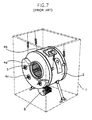
- FIG. 7 schematically illustrates a conventional drum washing machine with counterweights.
- the drum washing machine includes a housing 1, a tub 2 held by suspension arms in the housing 1, and a spin basket 3 rotatably provided in the tub 2.
- Counterweights 4a and 4b are attached to the tub 2 to prevent the production of vibration during the washing/hydro-extracting operation.
- the counterweight 4a attached to the front of the tub 2 is 11.4kg
- the counterweight 4b provided to the top of the tub 2 is 12.2kg.
- These counterweights 4a and 4b are made from cast iron and are joined to the tub 2 by bolts 4c.
- the above-described conventional drum washing machine has the following disadvantages:
- the conventional balancer using the counterweights only lowers the amplitude of vibrations generated during operation rather than eliminating them entirely.
- these counterweights are quiet heavy, it is difficult to install them on the tub and the overall weight of the washing machine is increased, resulting in difficult construction and transport.
- the bolts which fasten the counterweights to the tub, over long periods of use loosen due to corrosion or fatigue, resulting in noise, and, in the worst case, the possibility of damage to the balancer and the washing machine as well.
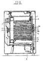
- FIG. 8 depicts a conventional drum washing machine employing such a liquid balancer.
- the drum washing machine of FIG. 8 includes a housing 1, a tub 2 held by suspension arms in the housing 1, an spin basket 3 rotatably installed within the tub 2, and an electric motor 8 installed below the tub 2 to rotate the spin basket 3.
- the tub 2 serves as a water tub, and the spin basket 3 is disposed within the tub 2 parallel to the ground rather than upright.
- One end 5a of a horizontally-supported shaft 5 is joined to the back of the spin basket 3.
- the other end 5b of the shaft 5 extends to the outside of the tub 2, and is connected to the motor 8 through a drive belt 6 so that the motor 8 can rotate the spin basket 3.
- the washing operation of such a drum washing machine is carried out by suds created by the rotation of the spin basket 3. After the washing and rinsing of the clothes, excess water is removed from the clothes by centrifugal force created by the spin basket 3 turning at high speeds during the hydro-extracting process so that they contain only enough moisture for ironing.
- a balancer is provided to the front of the spin basket 3 so as to prevent vibration from being produced during the high-speed rotation.
- the balancer is realized as an annular passageway 7 and a liquid, commonly a saline solution, of given quantity contained therein.
- the passageway 7 turns about the center of rotation S-S' rather than the geometric center of the spin basket 3 due to the laundry being gathered on one spot in the spin basket 3.
- the liquid housed in the passageway 7 is moved to oppose an imbalance resultant of the centrifugal force from the geometric center O-O' of the spin basket 3 and that of its center of rotation S-S'.
- the liquid balancer is incapable of dynamically balancing the spin basket. In order to compensate for such an imbalance sufficiently, the liquid balancer must be of great bulk. However, it is not easy to install such a heavy liquid balancer on the washing machine.
- FR-A-1213067 It is known from FR-A-1213067 to provide an appliance having a rotatably mounted drum for receiving a load of laundry, the drum including counterbalance means arranged to move within a chamber relative to the drum and concentric therewith, during rotation of the drum, towards a counterbalancing position in response to an imbalance in a load therein.
- An appliance according to the present invention is characterised by features recited in the characterising part of claim 1.
- the chambers contain liquid with a prescribed viscosity in addition to the counterbalance balls.
- At least one chamber is provided on each end of the drum.
- two chambers preferably of a different size are concentrically arranged on each end of the drum, the cover plate fixed to each end having two grooves therein corresponding to the grooves provided in the drum.
- the diameter of the balls in the radially inner chamber is smaller than the diameter of the balls in the radially outer chamber.
- a second cover plate is interposed between the cover plate and the drum, said second cover plate having a second groove which locates within the groove provided in the drum.
- FIG. 1 is a side-sectional view of a drum washing machine with a balancing device using balls in accordance with the present invention.
- the drum washing machine of FIG. 1 includes a housing 10, a tub 20 held in the housing 10, an spin basket 30 rotatably installed within the tub 20, and an electric motor 40, which rotates the spin basket 30, installed below the tub 20 to rotate the spin basket 30.
- the housing 10 is a quadrangular case, and the tub 20 is cylindrical in shape and horizontally held by four buffer springs 12 arranged on four sides in the housing 10.
- the spin basket 30, also of cylindrical shape, is horizontally disposed within the tub 20.
- Each of the buffer springs 12 has an upper end connected to the housing 10 and a lower end connected to the top of the tub 20.
- a pair of shock absorbers 13 are installed between the lower part of the tub 20 and the housing 10.
- Openings 11, 21 and 32a are formed on the front of the housing 10, a predetermined spot of the tub 20 corresponding to that of the housing 10, and a corresponding spot of the spin basket 30, respectively.
- a door (not illustrated) is disposed on the front of the housing 10 that opens and closes the entrance to the tub 20 and the spin basket 30.
- the spin basket 30 consists of a cylindrically-shaped body 31, and side panels 32 and 33 each constituting the front and back of the body 31.
- a plurality of holes 31a are uniformly distributed in the body 31 so that water can flow freely between the spin basket 30 and the tub 20
- a plurality of lifters 31b are provided to the body 31 and designed to protrude inward in the form of a "V", spaced 60° from each other.
- a horizontally-supported shaft 41 has one end 41 a connected to the side panel 33 that forms the back of the spin basket 30, and the other end 41 b extending to the rear of the tub 20 and connected to a first pulley 42.
- a belt 44 is provided between the first pulley 42 and a second pulley 43 that is connected to the motor 40's shaft 40a so that the rotating force of the motor 40 is transmitted to the spin basket 30.
- the shaft 41 is horizontally supported by a pair of bearings 46a and 46b placed in a bearing housing 45.
- a supporting member 47 has an outer end diverged in three directions and extends to the side panel 33's edge to be joined to the side panel 33 of the spin basket 30 so that the one end 41a of the shaft 41 is connected to the center of the supporting member 47.
- the spin basket 30 includes a pair of balancing devices 50 each provided to the both side panels 32 and 33 so as to remove the vibration and imbalance created during rotation.
- the balancing devices 50 are oppositely disposed respective to each other thereby offsetting movement created during rotation and enhancing the balancing characteristics.
- the balancing devices 50 are realized as annular chambers 51a and 51b that are formed on inner and outer parts of the side panels 32 and 33, and spherical balls 52a and 52b that are seated in the chambers 51a and 51b, respectively, and move along the corresponding chambers to oppose an imbalance in the spin basket 30.
- the chambers 51a and 51b contain a liquid of a predetermined viscosity, such as an oil, in order to facilitate the movement of the balls 52a and 52b and to enhance the balancing characteristics.
- a liquid of a predetermined viscosity such as an oil
- the balls 52a and 52b and the liquid relocate to a predetermined position to oppose the imbalance. If the magnitude of the imbalance does not exceed a predetermined critical point of counterbalance of the balancing devices, the balls 52a and 52b move close to each other to make the vibration amplitude zero so the liquid does not flow.
- the liquid is then also moved to oppose the imbalance, thereby countering the unbalanced state of the basket 30.
- Each of the balancing devices 50 includes at least one chamber and a plurality of the balls seated therein.
- the inner and outer chambers 51 a and 51 b are concentric to the axis and radially spaced from each other by a predetermined distance. They are sealed by welding.
- the balls 52a in the inner chambers 51a are designed to be smaller than the balls 52b in the outer chambers 51b so that there is a difference between the balancing effects of the inner and outer chambers 51a and 51 b to thereby ensuring more delicate counterbalancing action.
- the balancing devices 50 provided to the both side panels 32 and 33 are formed symmetrically, and the structure of the chambers 51a and 51 b on the side panel 32 will be described by way of example.
- the inner chambers 51a and the outer chambers 51b of different size have essentially the same construction, and the inner chambers 5la are now described as an example.
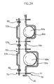
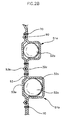
- FIGS. 2A and 2B are enlarged views of "A" of FIG. 1, and each depict the coupling structure of the chambers 51 a and 51 b.
- the chamber 51 a is constituted of the combination of a first groove 32b formed inward on the side panel 32 of the spin basket 30 and a second groove 53a formed outward corresponding to the first groove 32b. More specifically, the second groove 53a is formed on a secondary plate member 53, and the plate member 53 is joined to the side panel 32 of the spin basket 30 by the use of small bolts 70. Nuts 72 then screw onto the bolts with bolt heads 71 facing the inside of the spin basket 30. On both sides of the chamber 51 a are formed bent portions 32c and 53b. Packing material 90 is inserted between the bent portions 32c and 53b and compressed to a seal so as to eliminate leakage of the oil in the chambers 51a.
- FIG. 3 depicts a chamber coupling structure in accordance with a second preferred embodiment of the present invention.
- a chamber 51 a is constituted of the combination of a first groove 32b formed inward on the side panel 32 of the spin basket 30 and a second groove 53a formed outward corresponding to the first groove 32b.
- the second groove 53a is formed on a secondary plate member 53, and the plate member 53 is joined to the side panel 32 of the spin basket 30 by the use of rivets 80.
- the rivets 80 are pressed from the outside of the spin basket 30 to fasten the panel 32 and side panel 32 together.
- bent portions 32c and 53b On both sides of the chamber 51a are formed bent portions 32c and 53b. Packing material 90 is inserted between the bent portions 32c and 53b and compressed to a seal so as to eliminate fluid leakage.
- FIG. 4 depicts a chamber coupling structure in accordance with a third preferred embodiment of the present invention.
- a chamber 51 a is constituted of the combination of a first groove 32b formed inward on the side panel 32 of the spin basket 30 and a second groove 53a formed outward corresponding to the first groove 32b.
- the second groove 53a is formed on a secondary plate member 53, and the plate member 53 is joined to the side panel 32 of the spin basket 30 by welding.
- FIG. 5 depicts a chamber coupling structure in accordance with a fourth preferred embodiment of the present invention.
- a chamber 51 a is constituted of the combination of a first plate member 54 with a first annular groove 54a formed inward thereon and a second plate member 55 with a second annular groove 55a formed outward thereon corresponding to the first groove 54a.
- the first plate member 54 is connected to the second plate member 55 by welding, and a bolt 60 that adheres closely to the outer surface of a lifter 31b is used to fasten the members 54 and 55 to the side panel 32.
- the bolt 60 is disposed on the outer surface of the lifter 31 b, and its bolt head 62 adheres to the outside of one balancing device 50 located at the rear.
- a nut 61 screws onto the bolt 60 in front of the other balancing device 50 placed on the front so that the front and rear balancing devices 50 can join together, with the spin basket 30 between.
- the bolt 60 is fastened between the inner chamber 51a and the outer chamber 51b (refer to FIG. 1).
- a third groove 32d is formed on a portion of the side panel 32 corresponding to the first groove 54a of the first plate member 54 in order to accommodate the first groove 54a, and the combination of the first and second plate members 54 and 55 is designed to lie flush with the side panel 32.
- the contact points between the plate member 53 and the side panel 32, which form the chambers 51a and 51 b, do not lie in the plane created by the centers of the balls 52a and 52b. This is so because the first groove 32b's depth h 2 is different from the depth h 1 of the second groove 53a, allowing the balls 52a and 52b to freely move along the chambers.
- the first groove 32b and the second groove 53a are designed to respectively have different depths h 2 and h 1 , and the depth h 1 of the second groove 53a is larger than each radius "r" of the balls 52a and 52b.
- the depth h 1 of the second groove 53a is larger than 1/2 of the overall depth "h" of the chambers 51a and 51b.
- Each corner of the inner chamber 51 a and outer chamber 51 b is designed to be rounded to form curved portions R 1 and R 2 .
- the curvature of the curved portion R 1 is different from that of the curved portion R 2 so that the balls 52a and 52b move along the respective inner and outer chambers 51 a and 51b at the same speed.
- the relatively small and light ball 52a would move through the inner chamber 51 a faster than the ball 52b in the outer chamber 51 b.
- the curved portions R 1 of the inner chamber 51 a being more curved than those of the outer chamber 51b ensures that the balls 52a and 52b move along the corresponding inner and outer chambers 51 a and 51 b at the same speed.
- the following description relates to the operation of the drum washing machine with the inventive balancing devices.
- the washing machine removes soil from the garments by agitation accomplished by the spin basket 30 during washing. During the hydro-extracting action of the washing process, the garments are located on the lower part of the spin basket 30. If the spin basket 30 becomes unbalanced as it rotates at high speeds, the centrifugal force of the spin basket 30 moves the balls 52a and 52b along the chambers 51 a and 51 b to a position which will rebalance the basket 30, thereby eliminating vibrations and eccentric rotation of the spin basket 30.
- movable bodies consisting of the balls 51a and 51 b and liquid become situated on the opposite side of the imbalance.
- the balls 51a and 51 b move close to each other to eliminate the vibration (i.e. to make the geometric center and center of rotation of the spin basket 30 the same).
- the vibration amplitude becomes zero, the flow of the liquid within the chambers 51 a and 51 b is minimal. If the magnitude of the imbalance still exceeds the critical point of counterbalance, after the balls have moved into their counterbalancing position, the liquid is then also moved to oppose the imbalance, thereby countering the unbalanced state of the basket 30.
- the balls of the present invention make the vibration amplitude zero and counteract an imbalance in the spin basket to thereby eliminate resultant deformation of the spin basket.
- the inventive balancing devices may prevent unnecessary wear of the components used to support the rotation of the spin basket and noise created by friction.
- the balancing devices employ the balls and liquid at the same time, and have superior balancing characteristics with reduced bulk.
- the chambers of the balancing devices are easily formed by bolts and nuts or by welding, and the parts where the plate member and the side panel join together by welding are not exposed to the inside of the spin basket thereby preventing corrosion and oxidization of those joints. Additionally, the jointing portion of each chamber is not aligned with the center of each ball so that the balls are freely movable in the chambers.
Claims (10)
- Vorrichtung mit einer axial drehbar gelagerten Trommel (30) zur Aufnahme einer Ladung Wäsche, wobei die Trommel (30) eine Seitenplatte (32, 33), Auswuchtkugeln (52a, 52b), die dafür eingerichtet sind, als Antwort auf ein Ungleichgewicht in einer Ladung in der Trommel sich während der Drehung der Trommel (30) frei innerhalb einer Kammer (50) relativ zur Trommel (30) und konzentrisch damit in Richtung auf eine Auswuchtposition zu bewegen, und eine Deckplatte (53) an der Seitenplatte der Trommel (30) enthält, gekennzeichnet durch erste und zweite ringförmige Rinnen (32b, 53a), die in der Axialrichtung ausgerichtet sind, um die Kammer (50) auszubilden, wenn die Deckplatte (53) an der Seitenplatte der Trommel (30) befestigt ist, wobei die erste Rinne (32b) einwärts der Trommel an der Seitenplatte (32) ausgebildet ist und die zweite Rinne (53b) auswärts der Trommel an der Deckplatte (53) ausgebildet ist.
- Vorrichtung nach Anspruch 1, bei der die Rinnen (32b, 53a) ungleiche Tiefe haben.
- Vorrichtung nach Anspruch 1 oder 2, bei der die Kammer zusätzlich zu den Auswuchtkugeln (52a, 52b) eine Flüssigkeit mit einer vorgeschriebenen Viskosität enthält.
- Vorrichtung nach irgendeinem vorhergehenden Anspruch, bei der an jedem Ende der Trommel (30) mindestens eine Kammer (50) vorgesehen ist.
- Vorrichtung nach Anspruch 4, bei der an jedem Ende der Trommel (30) mit einer daran befestigten Deckplatte (32) zwei Kammern (50) konzentrisch angeordnet sind und jeweils zwei Rinnen (53a) aufweisen, die den Rinnen (32b) entsprechen, die in der Seitenplatte der Trommel (30) vorgesehen sind.
- Vorrichtung nach Anspruch 5, bei der die zwei Kammern (50) an jedem Ende verschiedene Abmessungen haben.
- Vorrichtung nach irgendeinem vorhergehenden Anspruch, bei der der Durchmesser der Kugeln (52a, 52b) in der radial inneren Kammer (50) kleiner als der Durchmesser der Kugeln (52a, 52b) in der radial äußeren Kammer (50) ist.
- Vorrichtung nach irgendeinem vorhergehenden Anspruch, bei der die Deckplatte (32) mittels Bolzen (70) an der Trommel (30) befestigt ist.
- Vorrichtung nach irgendeinem der Ansprüche 1 bis 8, bei der die Deckplatte (53) mittels Nieten (80) an der Trommel (30) befestigt ist.
- Vorrichtung nach Anspruch 1, bei der eine zweite Deckplatte (54) zwischen der Deckplatte (53) und der Trommel (30) angeordnet ist, wobei die zweite Deckplatte (54) eine zweite Rinne (54a) aufweist, die innerhalb der Rinne (32b) liegt, die in der Seitenplatte der Trommel (30) vorgesehen ist.
Applications Claiming Priority (8)
| Application Number | Priority Date | Filing Date | Title |
|---|---|---|---|
| KR2019950050073U KR970039214U (ko) | 1995-12-28 | 1995-12-28 | 드럼세탁기의 진동방지장치 |
| KR9550073 | 1995-12-28 | ||
| KR9603764 | 1996-02-15 | ||
| KR1019960003764A KR100187239B1 (ko) | 1996-02-15 | 1996-02-15 | 드럼세탁기의 드럼 |
| KR9611524 | 1996-05-11 | ||
| KR2019960011524U KR0134130Y1 (ko) | 1996-05-11 | 1996-05-11 | 드럼 세탁기의 밸런싱장치 |
| KR9613846 | 1996-05-30 | ||
| KR2019960013846U KR200145372Y1 (ko) | 1996-05-30 | 1996-05-30 | 드럼세탁기의 밸런싱장치 |
Publications (3)
| Publication Number | Publication Date |
|---|---|
| EP0781882A1 EP0781882A1 (de) | 1997-07-02 |
| EP0781882B1 EP0781882B1 (de) | 2000-06-14 |
| EP0781882B2 true EP0781882B2 (de) | 2005-08-10 |
Family
ID=27483097
Family Applications (1)
| Application Number | Title | Priority Date | Filing Date |
|---|---|---|---|
| EP96309482A Expired - Lifetime EP0781882B2 (de) | 1995-12-28 | 1996-12-24 | Trommelmaschine mit Auswuchtvorrichtungen |
Country Status (6)
| Country | Link |
|---|---|
| US (1) | US5850748A (de) |
| EP (1) | EP0781882B2 (de) |
| JP (1) | JP2915863B2 (de) |
| CN (1) | CN1074067C (de) |
| DE (1) | DE69608876T3 (de) |
| TR (1) | TR199601070A2 (de) |
Cited By (1)
| Publication number | Priority date | Publication date | Assignee | Title |
|---|---|---|---|---|
| CN107916545A (zh) * | 2017-12-07 | 2018-04-17 | 青岛海尔洗衣机有限公司 | 一种洗衣机箱体及洗衣机 |
Families Citing this family (43)
| Publication number | Priority date | Publication date | Assignee | Title |
|---|---|---|---|---|
| SE505096C2 (sv) * | 1995-10-30 | 1997-06-23 | Skf Ab | Automatisk balanseringsanordning för storskaliga roterande enheter eller system |
| KR100224450B1 (ko) * | 1996-05-23 | 1999-10-15 | 윤종용 | 드럼세탁기의 밸런싱장치 |
| KR100237689B1 (ko) * | 1996-05-30 | 2000-01-15 | 윤종용 | 드럼세탁기의 밸런싱장치 |
| JPH10216391A (ja) * | 1997-02-12 | 1998-08-18 | Toshiba Corp | ドラム式洗濯機 |
| KR100268254B1 (ko) * | 1997-12-31 | 2000-10-16 | 윤종용 | 드럼 세탁기의 볼 밸런서 제조방법 |
| US6442782B1 (en) | 2000-04-27 | 2002-09-03 | Maytag Corporation | Ball balancing mechanism |
| US6578225B2 (en) | 2000-05-25 | 2003-06-17 | Skf Autobalance Systems Ab | Low-speed prebalancing for washing machines |
| SE518472C2 (sv) * | 2001-02-06 | 2002-10-15 | Electrolux Ab | Anordning för balansering av roterande kroppar i t.ex. tvättmaskiner |
| US6507799B2 (en) | 2001-02-26 | 2003-01-14 | Honeywell International Inc. | Method and apparatus for reducing microprocessor speed requirements in data acquisition applications |
| US6532422B1 (en) | 2001-06-29 | 2003-03-11 | Honeywell International, Inc. | Simultaneous injection method and system for a self-balancing rotatable apparatus |
| US6622105B2 (en) | 2001-09-10 | 2003-09-16 | Honeywell International Inc. | Dynamic correlation extension for a self-balancing rotatable apparatus |
| US6665625B2 (en) | 2001-09-10 | 2003-12-16 | Honeywell International Inc | Energy-based thresholds applied dynamic balancing |
| US6701561B2 (en) | 2001-09-10 | 2004-03-09 | Honeywell International Inc. | Method and system for detecting fluid injection from stationary to rotating members |
| US6647790B2 (en) | 2001-11-15 | 2003-11-18 | Honeywell International Inc. | Fixed-bandwidth correlation window method and system for a self-balancing rotatable apparatus |
| US6546354B1 (en) | 2001-11-15 | 2003-04-08 | Honeywell International, Inc. | Resonance identification extension for a self-balancing rotatable apparatus |
| US6687572B2 (en) | 2001-11-15 | 2004-02-03 | Honeywell International Inc. | Supervisory method and system for improved control model updates applied to dynamic balancing |
| US6795792B2 (en) * | 2001-11-15 | 2004-09-21 | Honeywell International Inc. | Continuous flow method and system for placement of balancing fluid on a rotating device requiring dynamic balancing |
| US6662682B2 (en) | 2001-11-15 | 2003-12-16 | Honeywell International Inc. | Dynamic balancing application mass placement |
| US6681430B2 (en) | 2001-11-15 | 2004-01-27 | Honeywell International Inc. | Method and system for mechanizing simultaneous multi-actuator actions applied to dynamic balancing |
| US6775870B2 (en) | 2001-11-15 | 2004-08-17 | Honeywell International Inc. | Data manipulation method and system for a self-balancing rotatable apparatus |
| US20040221624A1 (en) * | 2002-06-20 | 2004-11-11 | Silvano Fumagalli | Washington machine for household use with two compartments |
| CN100383322C (zh) * | 2002-07-05 | 2008-04-23 | 乐金电子(天津)电器有限公司 | 滚筒洗衣机的机箱与顶部托架的固定结构 |
| KR100587307B1 (ko) * | 2004-06-09 | 2006-06-08 | 엘지전자 주식회사 | 드럼세탁기 및 드럼세탁기의 드럼 |
| KR100765277B1 (ko) * | 2005-01-10 | 2007-10-09 | 엘지전자 주식회사 | 드럼세탁기 |
| EP1862578B1 (de) | 2006-06-01 | 2012-06-27 | Samsung Electronics Co., Ltd. | Trommelwaschmaschine |
| KR101003352B1 (ko) * | 2006-06-01 | 2010-12-23 | 삼성전자주식회사 | 밸런서를 구비한 세탁기 |
| KR101273587B1 (ko) * | 2006-06-01 | 2013-06-11 | 삼성전자주식회사 | 드럼세탁기 |
| EP2354293B1 (de) * | 2006-06-01 | 2017-11-01 | Samsung Electronics Co., Ltd. | Waschmaschine mit Ausgleichsregler |
| KR101267333B1 (ko) * | 2006-09-22 | 2013-05-23 | 삼성전자주식회사 | 드럼세탁기 |
| KR101332860B1 (ko) * | 2006-10-26 | 2013-11-22 | 삼성전자주식회사 | 세탁기 |
| KR100960068B1 (ko) * | 2006-11-10 | 2010-05-31 | 삼성전자주식회사 | 볼밸런서 및 이를 구비한 세탁기 |
| KR101356645B1 (ko) * | 2007-04-19 | 2014-02-03 | 삼성전자주식회사 | 밸런서와 이를 구비하는 드럼세탁기 |
| US8516885B1 (en) | 2009-01-12 | 2013-08-27 | Doug Fortune | Rotating object dynamic balancing system and method |
| JP5124544B2 (ja) * | 2009-08-28 | 2013-01-23 | 日立アプライアンス株式会社 | 洗濯機 |
| KR20120045887A (ko) * | 2010-11-01 | 2012-05-09 | 삼성전자주식회사 | 세탁기 |
| DE102010062520A1 (de) * | 2010-12-07 | 2012-06-14 | BSH Bosch und Siemens Hausgeräte GmbH | Hausgerät zur Pflege von Wäschestücken sowie Verfahren zum Befestigen einer Riemenscheibe einer Riemenantriebsvorrichtung eines derartigen Hausgeräts |
| CN102154801B (zh) | 2011-01-11 | 2016-08-17 | 海尔集团公司 | 节水滚筒洗衣机及洗衣方法 |
| CN103243526B (zh) * | 2013-05-28 | 2016-08-24 | 李家海 | 自动调节到平稳状态的脱水机 |
| US9534335B2 (en) | 2014-05-09 | 2017-01-03 | Whirlpool Corporation | Laundry treating appliance with integrated dynamic balancer |
| US9540754B2 (en) | 2014-05-09 | 2017-01-10 | Whirlpool Corporation | Laundry treating appliance with integrated dynamic balancer |
| US10253442B2 (en) * | 2014-09-05 | 2019-04-09 | Lg Electronics Inc. | Top-loading type washing machine |
| CN107829260B (zh) * | 2017-10-30 | 2023-09-15 | 珠海格力电器股份有限公司 | 滚筒式洗衣机的动平衡装置、滚筒式洗衣机的内筒组件及滚筒式洗衣机 |
| US20190242047A1 (en) * | 2018-02-07 | 2019-08-08 | Haier Us Appliance Solutions, Inc. | Washing machine appliances and methods of operation |
Citations (6)
| Publication number | Priority date | Publication date | Assignee | Title |
|---|---|---|---|---|
| US2984094A (en) † | 1957-11-08 | 1961-05-16 | Frame Sa | Washing machine |
| DE1118739B (de) † | 1957-11-08 | 1961-12-07 | Frame Sa | Vorrichtung zum Ausgleichen der Unwucht von Schleudertrommeln in Waescheschleudern und Waschmaschinen |
| US3799619A (en) † | 1972-05-18 | 1974-03-26 | Wagner K | Vibration dampening assembly |
| US4060009A (en) † | 1974-10-30 | 1977-11-29 | Chrysler United Kingdom Limited | Balancing rotors |
| EP0607678A1 (de) † | 1992-12-28 | 1994-07-27 | Whirlpool Corporation | Auswuchtvorrichtung für eine automatische Waschmaschine |
| EP0725179A1 (de) † | 1995-02-01 | 1996-08-07 | ELECTROLUX ZANUSSI ELETTRODOMESTICI S.p.A. | Vorrichtung zum Vermeiden der Unwucht einer Waschmaschinetrommel |
Family Cites Families (15)
| Publication number | Priority date | Publication date | Assignee | Title |
|---|---|---|---|---|
| FR1213067A (fr) * | 1957-11-08 | 1960-03-29 | Frame | Machine à laver |
| FR1262528A (fr) * | 1960-07-19 | 1961-05-26 | Frame | Machine à laver |
| DE1912481U (de) * | 1961-07-24 | 1965-03-18 | Siemens Elektrogeraete Gmbh | Einrichtung zum schleudern von wasche mit elastischer aufhaengung des trommelaggregats. |
| JPS5351671A (en) * | 1976-10-20 | 1978-05-11 | Hitachi Ltd | Drum type washing machine |
| GB1598399A (en) * | 1977-06-02 | 1981-09-16 | Hitachi Ltd | Drum type automatic electric washing machine |
| JPS5945400B2 (ja) * | 1977-07-29 | 1984-11-06 | 株式会社日立製作所 | ドラム式全自動洗たく機 |
| JPS54107979U (de) * | 1978-01-18 | 1979-07-30 | ||
| JPS54140064A (en) * | 1978-04-24 | 1979-10-30 | Toshiba Corp | Dynamic balancing apparatus |
| IT1136452B (it) * | 1980-07-03 | 1986-08-27 | Zanussi A Spa Industrie | Vasca in materia plastica per macchine lavabiancheria |
| JPS6319040U (de) * | 1986-07-23 | 1988-02-08 | ||
| SU1461796A1 (ru) * | 1987-03-25 | 1989-02-28 | Рижский политехнический институт им.А.Я.Пельше | Устройство балансировани центрифуги стиральной машины |
| JPH0696069B2 (ja) * | 1989-03-28 | 1994-11-30 | 三洋電機株式会社 | 洗濯機 |
| JPH04122387A (ja) * | 1990-09-14 | 1992-04-22 | Matsushita Electric Ind Co Ltd | 自動洗濯機 |
| CA2069120C (en) * | 1992-05-21 | 2005-04-26 | Anton Gasafi | Weight compensating method and apparatus |
| US5460017A (en) * | 1992-05-21 | 1995-10-24 | Eti Technologies Inc. | Weight compensating apparatus |
-
1996
- 1996-12-24 EP EP96309482A patent/EP0781882B2/de not_active Expired - Lifetime
- 1996-12-24 DE DE69608876T patent/DE69608876T3/de not_active Expired - Lifetime
- 1996-12-26 JP JP8348970A patent/JP2915863B2/ja not_active Expired - Fee Related
- 1996-12-27 US US08/774,876 patent/US5850748A/en not_active Expired - Lifetime
- 1996-12-27 TR TR96/01070A patent/TR199601070A2/xx unknown
- 1996-12-28 CN CN96123928A patent/CN1074067C/zh not_active Expired - Fee Related
Patent Citations (6)
| Publication number | Priority date | Publication date | Assignee | Title |
|---|---|---|---|---|
| US2984094A (en) † | 1957-11-08 | 1961-05-16 | Frame Sa | Washing machine |
| DE1118739B (de) † | 1957-11-08 | 1961-12-07 | Frame Sa | Vorrichtung zum Ausgleichen der Unwucht von Schleudertrommeln in Waescheschleudern und Waschmaschinen |
| US3799619A (en) † | 1972-05-18 | 1974-03-26 | Wagner K | Vibration dampening assembly |
| US4060009A (en) † | 1974-10-30 | 1977-11-29 | Chrysler United Kingdom Limited | Balancing rotors |
| EP0607678A1 (de) † | 1992-12-28 | 1994-07-27 | Whirlpool Corporation | Auswuchtvorrichtung für eine automatische Waschmaschine |
| EP0725179A1 (de) † | 1995-02-01 | 1996-08-07 | ELECTROLUX ZANUSSI ELETTRODOMESTICI S.p.A. | Vorrichtung zum Vermeiden der Unwucht einer Waschmaschinetrommel |
Cited By (1)
| Publication number | Priority date | Publication date | Assignee | Title |
|---|---|---|---|---|
| CN107916545A (zh) * | 2017-12-07 | 2018-04-17 | 青岛海尔洗衣机有限公司 | 一种洗衣机箱体及洗衣机 |
Also Published As
| Publication number | Publication date |
|---|---|
| EP0781882B1 (de) | 2000-06-14 |
| DE69608876T3 (de) | 2006-05-24 |
| US5850748A (en) | 1998-12-22 |
| CN1160099A (zh) | 1997-09-24 |
| TR199601070A2 (tr) | 1997-07-21 |
| EP0781882A1 (de) | 1997-07-02 |
| DE69608876D1 (de) | 2000-07-20 |
| CN1074067C (zh) | 2001-10-31 |
| JPH09187597A (ja) | 1997-07-22 |
| JP2915863B2 (ja) | 1999-07-05 |
| DE69608876T2 (de) | 2001-02-22 |
Similar Documents
| Publication | Publication Date | Title |
|---|---|---|
| EP0781882B2 (de) | Trommelmaschine mit Auswuchtvorrichtungen | |
| US5850749A (en) | Balancing device for a drum washing machine | |
| JP2957144B2 (ja) | 洗濯機用ボールバランサ | |
| EP1605088B1 (de) | Trommelwaschmaschine und dazugehörige Trommel | |
| JP2755567B2 (ja) | ドラム型洗濯機の洗濯槽 | |
| EP0810318B1 (de) | Waschmaschine | |
| EP0808932B1 (de) | Waschmaschine | |
| CA2111541A1 (en) | Balancer for an automatic washer | |
| US5746069A (en) | Clothes washing machine having upper and lower dynamic balancers | |
| EP0806515B1 (de) | Waschmaschine | |
| EP0810319B1 (de) | Waschmaschine | |
| KR0134130Y1 (ko) | 드럼 세탁기의 밸런싱장치 | |
| KR0136040Y1 (ko) | 드럼세탁기의 밸런싱장치 | |
| KR0136039Y1 (ko) | 드럼세탁기의 밸런싱장치 | |
| KR0136042Y1 (ko) | 드럼세탁기의 밸런싱장치 | |
| KR0136041Y1 (ko) | 드럼세탁기의 밸런싱장치 | |
| JPS5945400B2 (ja) | ドラム式全自動洗たく機 | |
| KR200145370Y1 (ko) | 드럼세탁기의 밸런싱장치 | |
| KR0136037Y1 (ko) | 드럼세탁기의 밸런싱장치 | |
| KR200145372Y1 (ko) | 드럼세탁기의 밸런싱장치 |
Legal Events
| Date | Code | Title | Description |
|---|---|---|---|
| PUAI | Public reference made under article 153(3) epc to a published international application that has entered the european phase |
Free format text: ORIGINAL CODE: 0009012 |
|
| AK | Designated contracting states |
Kind code of ref document: A1 Designated state(s): DE FR GB IT NL |
|
| 17P | Request for examination filed |
Effective date: 19970811 |
|
| 17Q | First examination report despatched |
Effective date: 19990120 |
|
| GRAG | Despatch of communication of intention to grant |
Free format text: ORIGINAL CODE: EPIDOS AGRA |
|
| GRAG | Despatch of communication of intention to grant |
Free format text: ORIGINAL CODE: EPIDOS AGRA |
|
| GRAH | Despatch of communication of intention to grant a patent |
Free format text: ORIGINAL CODE: EPIDOS IGRA |
|
| GRAH | Despatch of communication of intention to grant a patent |
Free format text: ORIGINAL CODE: EPIDOS IGRA |
|
| GRAA | (expected) grant |
Free format text: ORIGINAL CODE: 0009210 |
|
| AK | Designated contracting states |
Kind code of ref document: B1 Designated state(s): DE FR GB IT NL |
|
| PG25 | Lapsed in a contracting state [announced via postgrant information from national office to epo] |
Ref country code: NL Free format text: LAPSE BECAUSE OF FAILURE TO SUBMIT A TRANSLATION OF THE DESCRIPTION OR TO PAY THE FEE WITHIN THE PRESCRIBED TIME-LIMIT Effective date: 20000614 |
|
| REF | Corresponds to: |
Ref document number: 69608876 Country of ref document: DE Date of ref document: 20000720 |
|
| ET | Fr: translation filed | ||
| ITF | It: translation for a ep patent filed |
Owner name: STUDIO TORTA S.R.L. |
|
| NLV1 | Nl: lapsed or annulled due to failure to fulfill the requirements of art. 29p and 29m of the patents act | ||
| PLBQ | Unpublished change to opponent data |
Free format text: ORIGINAL CODE: EPIDOS OPPO |
|
| PLBI | Opposition filed |
Free format text: ORIGINAL CODE: 0009260 |
|
| PLBF | Reply of patent proprietor to notice(s) of opposition |
Free format text: ORIGINAL CODE: EPIDOS OBSO |
|
| 26 | Opposition filed |
Opponent name: MIELE & CIE. GMBH & CO. PATENTE/MARKEN Effective date: 20010314 Opponent name: AKTIEBOLAGET ELECTROLUX Effective date: 20010313 |
|
| PLBF | Reply of patent proprietor to notice(s) of opposition |
Free format text: ORIGINAL CODE: EPIDOS OBSO |
|
| PLBF | Reply of patent proprietor to notice(s) of opposition |
Free format text: ORIGINAL CODE: EPIDOS OBSO |
|
| REG | Reference to a national code |
Ref country code: GB Ref legal event code: IF02 |
|
| PLAW | Interlocutory decision in opposition |
Free format text: ORIGINAL CODE: EPIDOS IDOP |
|
| APAC | Appeal dossier modified |
Free format text: ORIGINAL CODE: EPIDOS NOAPO |
|
| APAC | Appeal dossier modified |
Free format text: ORIGINAL CODE: EPIDOS NOAPO |
|
| APAC | Appeal dossier modified |
Free format text: ORIGINAL CODE: EPIDOS NOAPO |
|
| PLAB | Opposition data, opponent's data or that of the opponent's representative modified |
Free format text: ORIGINAL CODE: 0009299OPPO |
|
| R26 | Opposition filed (corrected) |
Opponent name: MIELE & CIE. KG Effective date: 20010314 Opponent name: AKTIEBOLAGET ELECTROLUX Effective date: 20010313 |
|
| PLBQ | Unpublished change to opponent data |
Free format text: ORIGINAL CODE: EPIDOS OPPO |
|
| PLAB | Opposition data, opponent's data or that of the opponent's representative modified |
Free format text: ORIGINAL CODE: 0009299OPPO |
|
| R26 | Opposition filed (corrected) |
Opponent name: MIELE & CIE. KG Effective date: 20010314 Opponent name: AKTIEBOLAGET ELECTROLUX Effective date: 20010313 |
|
| APBU | Appeal procedure closed |
Free format text: ORIGINAL CODE: EPIDOSNNOA9O |
|
| APAA | Appeal reference recorded |
Free format text: ORIGINAL CODE: EPIDOS REFN |
|
| APBU | Appeal procedure closed |
Free format text: ORIGINAL CODE: EPIDOSNNOA9O |
|
| PUAH | Patent maintained in amended form |
Free format text: ORIGINAL CODE: 0009272 |
|
| STAA | Information on the status of an ep patent application or granted ep patent |
Free format text: STATUS: PATENT MAINTAINED AS AMENDED |
|
| 27A | Patent maintained in amended form |
Effective date: 20050810 |
|
| AK | Designated contracting states |
Kind code of ref document: B2 Designated state(s): DE FR GB IT NL |
|
| APAH | Appeal reference modified |
Free format text: ORIGINAL CODE: EPIDOSCREFNO |
|
| ET3 | Fr: translation filed ** decision concerning opposition | ||
| PGFP | Annual fee paid to national office [announced via postgrant information from national office to epo] |
Ref country code: DE Payment date: 20131213 Year of fee payment: 18 Ref country code: GB Payment date: 20131216 Year of fee payment: 18 |
|
| PGFP | Annual fee paid to national office [announced via postgrant information from national office to epo] |
Ref country code: FR Payment date: 20131213 Year of fee payment: 18 Ref country code: IT Payment date: 20131212 Year of fee payment: 18 |
|
| REG | Reference to a national code |
Ref country code: DE Ref legal event code: R119 Ref document number: 69608876 Country of ref document: DE |
|
| GBPC | Gb: european patent ceased through non-payment of renewal fee |
Effective date: 20141224 |
|
| REG | Reference to a national code |
Ref country code: FR Ref legal event code: ST Effective date: 20150831 |
|
| PG25 | Lapsed in a contracting state [announced via postgrant information from national office to epo] |
Ref country code: DE Free format text: LAPSE BECAUSE OF NON-PAYMENT OF DUE FEES Effective date: 20150701 Ref country code: GB Free format text: LAPSE BECAUSE OF NON-PAYMENT OF DUE FEES Effective date: 20141224 |
|
| PG25 | Lapsed in a contracting state [announced via postgrant information from national office to epo] |
Ref country code: FR Free format text: LAPSE BECAUSE OF NON-PAYMENT OF DUE FEES Effective date: 20141231 |
|
| PG25 | Lapsed in a contracting state [announced via postgrant information from national office to epo] |
Ref country code: IT Free format text: LAPSE BECAUSE OF NON-PAYMENT OF DUE FEES Effective date: 20141224 |