EP0781465B1 - Optische vorrichtung - Google Patents
Optische vorrichtung Download PDFInfo
- Publication number
- EP0781465B1 EP0781465B1 EP95931340A EP95931340A EP0781465B1 EP 0781465 B1 EP0781465 B1 EP 0781465B1 EP 95931340 A EP95931340 A EP 95931340A EP 95931340 A EP95931340 A EP 95931340A EP 0781465 B1 EP0781465 B1 EP 0781465B1
- Authority
- EP
- European Patent Office
- Prior art keywords
- region
- optical
- waveguide
- waveguide region
- layer
- Prior art date
- Legal status (The legal status is an assumption and is not a legal conclusion. Google has not performed a legal analysis and makes no representation as to the accuracy of the status listed.)
- Expired - Lifetime
Links
- 230000003287 optical effect Effects 0.000 title claims description 62
- 230000005855 radiation Effects 0.000 claims description 32
- 239000011149 active material Substances 0.000 claims description 30
- 239000000463 material Substances 0.000 claims description 20
- 239000004065 semiconductor Substances 0.000 claims description 13
- 239000000758 substrate Substances 0.000 claims description 13
- 230000007423 decrease Effects 0.000 claims description 6
- 230000008878 coupling Effects 0.000 claims description 4
- 238000010168 coupling process Methods 0.000 claims description 4
- 238000005859 coupling reaction Methods 0.000 claims description 4
- 238000000576 coating method Methods 0.000 claims description 3
- 238000001914 filtration Methods 0.000 claims 1
- 230000003321 amplification Effects 0.000 description 21
- 238000003199 nucleic acid amplification method Methods 0.000 description 21
- 238000000034 method Methods 0.000 description 8
- 230000000694 effects Effects 0.000 description 6
- 238000002488 metal-organic chemical vapour deposition Methods 0.000 description 5
- 230000009022 nonlinear effect Effects 0.000 description 5
- 238000002310 reflectometry Methods 0.000 description 5
- 230000009471 action Effects 0.000 description 4
- 238000006243 chemical reaction Methods 0.000 description 4
- 239000000835 fiber Substances 0.000 description 4
- 239000013307 optical fiber Substances 0.000 description 4
- 230000008901 benefit Effects 0.000 description 3
- 239000012141 concentrate Substances 0.000 description 3
- 230000004048 modification Effects 0.000 description 3
- 238000012986 modification Methods 0.000 description 3
- VYPSYNLAJGMNEJ-UHFFFAOYSA-N Silicium dioxide Chemical compound O=[Si]=O VYPSYNLAJGMNEJ-UHFFFAOYSA-N 0.000 description 2
- 230000005540 biological transmission Effects 0.000 description 2
- 238000005253 cladding Methods 0.000 description 2
- 230000010363 phase shift Effects 0.000 description 2
- 238000005086 pumping Methods 0.000 description 2
- 229910000530 Gallium indium arsenide Inorganic materials 0.000 description 1
- 239000000969 carrier Substances 0.000 description 1
- 239000011248 coating agent Substances 0.000 description 1
- 230000021615 conjugation Effects 0.000 description 1
- 230000001419 dependent effect Effects 0.000 description 1
- 238000010586 diagram Methods 0.000 description 1
- 239000003989 dielectric material Substances 0.000 description 1
- 239000006185 dispersion Substances 0.000 description 1
- 239000002019 doping agent Substances 0.000 description 1
- 238000005530 etching Methods 0.000 description 1
- 230000009021 linear effect Effects 0.000 description 1
- 238000004519 manufacturing process Methods 0.000 description 1
- 238000001465 metallisation Methods 0.000 description 1
- 230000008569 process Effects 0.000 description 1
- 235000012239 silicon dioxide Nutrition 0.000 description 1
- 239000000377 silicon dioxide Substances 0.000 description 1
Images

Classifications
-
- H—ELECTRICITY
- H01—ELECTRIC ELEMENTS
- H01S—DEVICES USING THE PROCESS OF LIGHT AMPLIFICATION BY STIMULATED EMISSION OF RADIATION [LASER] TO AMPLIFY OR GENERATE LIGHT; DEVICES USING STIMULATED EMISSION OF ELECTROMAGNETIC RADIATION IN WAVE RANGES OTHER THAN OPTICAL
- H01S5/00—Semiconductor lasers
- H01S5/50—Amplifier structures not provided for in groups H01S5/02 - H01S5/30
-
- H—ELECTRICITY
- H01—ELECTRIC ELEMENTS
- H01S—DEVICES USING THE PROCESS OF LIGHT AMPLIFICATION BY STIMULATED EMISSION OF RADIATION [LASER] TO AMPLIFY OR GENERATE LIGHT; DEVICES USING STIMULATED EMISSION OF ELECTROMAGNETIC RADIATION IN WAVE RANGES OTHER THAN OPTICAL
- H01S5/00—Semiconductor lasers
- H01S5/02—Structural details or components not essential to laser action
- H01S5/026—Monolithically integrated components, e.g. waveguides, monitoring photo-detectors, drivers
-
- H—ELECTRICITY
- H01—ELECTRIC ELEMENTS
- H01S—DEVICES USING THE PROCESS OF LIGHT AMPLIFICATION BY STIMULATED EMISSION OF RADIATION [LASER] TO AMPLIFY OR GENERATE LIGHT; DEVICES USING STIMULATED EMISSION OF ELECTROMAGNETIC RADIATION IN WAVE RANGES OTHER THAN OPTICAL
- H01S5/00—Semiconductor lasers
- H01S5/10—Construction or shape of the optical resonator, e.g. extended or external cavity, coupled cavities, bent-guide, varying width, thickness or composition of the active region
-
- H—ELECTRICITY
- H01—ELECTRIC ELEMENTS
- H01S—DEVICES USING THE PROCESS OF LIGHT AMPLIFICATION BY STIMULATED EMISSION OF RADIATION [LASER] TO AMPLIFY OR GENERATE LIGHT; DEVICES USING STIMULATED EMISSION OF ELECTROMAGNETIC RADIATION IN WAVE RANGES OTHER THAN OPTICAL
- H01S2301/00—Functional characteristics
- H01S2301/18—Semiconductor lasers with special structural design for influencing the near- or far-field
-
- H—ELECTRICITY
- H01—ELECTRIC ELEMENTS
- H01S—DEVICES USING THE PROCESS OF LIGHT AMPLIFICATION BY STIMULATED EMISSION OF RADIATION [LASER] TO AMPLIFY OR GENERATE LIGHT; DEVICES USING STIMULATED EMISSION OF ELECTROMAGNETIC RADIATION IN WAVE RANGES OTHER THAN OPTICAL
- H01S3/00—Lasers, i.e. devices using stimulated emission of electromagnetic radiation in the infrared, visible or ultraviolet wave range
- H01S3/005—Optical devices external to the laser cavity, specially adapted for lasers, e.g. for homogenisation of the beam or for manipulating laser pulses, e.g. pulse shaping
-
- H—ELECTRICITY
- H01—ELECTRIC ELEMENTS
- H01S—DEVICES USING THE PROCESS OF LIGHT AMPLIFICATION BY STIMULATED EMISSION OF RADIATION [LASER] TO AMPLIFY OR GENERATE LIGHT; DEVICES USING STIMULATED EMISSION OF ELECTROMAGNETIC RADIATION IN WAVE RANGES OTHER THAN OPTICAL
- H01S5/00—Semiconductor lasers
- H01S5/005—Optical components external to the laser cavity, specially adapted therefor, e.g. for homogenisation or merging of the beams or for manipulating laser pulses, e.g. pulse shaping
-
- H—ELECTRICITY
- H01—ELECTRIC ELEMENTS
- H01S—DEVICES USING THE PROCESS OF LIGHT AMPLIFICATION BY STIMULATED EMISSION OF RADIATION [LASER] TO AMPLIFY OR GENERATE LIGHT; DEVICES USING STIMULATED EMISSION OF ELECTROMAGNETIC RADIATION IN WAVE RANGES OTHER THAN OPTICAL
- H01S5/00—Semiconductor lasers
- H01S5/06—Arrangements for controlling the laser output parameters, e.g. by operating on the active medium
- H01S5/0607—Arrangements for controlling the laser output parameters, e.g. by operating on the active medium by varying physical parameters other than the potential of the electrodes, e.g. by an electric or magnetic field, mechanical deformation, pressure, light, temperature
- H01S5/0608—Arrangements for controlling the laser output parameters, e.g. by operating on the active medium by varying physical parameters other than the potential of the electrodes, e.g. by an electric or magnetic field, mechanical deformation, pressure, light, temperature controlled by light, e.g. optical switch
-
- H—ELECTRICITY
- H01—ELECTRIC ELEMENTS
- H01S—DEVICES USING THE PROCESS OF LIGHT AMPLIFICATION BY STIMULATED EMISSION OF RADIATION [LASER] TO AMPLIFY OR GENERATE LIGHT; DEVICES USING STIMULATED EMISSION OF ELECTROMAGNETIC RADIATION IN WAVE RANGES OTHER THAN OPTICAL
- H01S5/00—Semiconductor lasers
- H01S5/06—Arrangements for controlling the laser output parameters, e.g. by operating on the active medium
- H01S5/062—Arrangements for controlling the laser output parameters, e.g. by operating on the active medium by varying the potential of the electrodes
- H01S5/0625—Arrangements for controlling the laser output parameters, e.g. by operating on the active medium by varying the potential of the electrodes in multi-section lasers
-
- H—ELECTRICITY
- H01—ELECTRIC ELEMENTS
- H01S—DEVICES USING THE PROCESS OF LIGHT AMPLIFICATION BY STIMULATED EMISSION OF RADIATION [LASER] TO AMPLIFY OR GENERATE LIGHT; DEVICES USING STIMULATED EMISSION OF ELECTROMAGNETIC RADIATION IN WAVE RANGES OTHER THAN OPTICAL
- H01S5/00—Semiconductor lasers
- H01S5/06—Arrangements for controlling the laser output parameters, e.g. by operating on the active medium
- H01S5/068—Stabilisation of laser output parameters
- H01S5/0683—Stabilisation of laser output parameters by monitoring the optical output parameters
-
- H—ELECTRICITY
- H01—ELECTRIC ELEMENTS
- H01S—DEVICES USING THE PROCESS OF LIGHT AMPLIFICATION BY STIMULATED EMISSION OF RADIATION [LASER] TO AMPLIFY OR GENERATE LIGHT; DEVICES USING STIMULATED EMISSION OF ELECTROMAGNETIC RADIATION IN WAVE RANGES OTHER THAN OPTICAL
- H01S5/00—Semiconductor lasers
- H01S5/10—Construction or shape of the optical resonator, e.g. extended or external cavity, coupled cavities, bent-guide, varying width, thickness or composition of the active region
- H01S5/1053—Comprising an active region having a varying composition or cross-section in a specific direction
- H01S5/1064—Comprising an active region having a varying composition or cross-section in a specific direction varying width along the optical axis
-
- H—ELECTRICITY
- H01—ELECTRIC ELEMENTS
- H01S—DEVICES USING THE PROCESS OF LIGHT AMPLIFICATION BY STIMULATED EMISSION OF RADIATION [LASER] TO AMPLIFY OR GENERATE LIGHT; DEVICES USING STIMULATED EMISSION OF ELECTROMAGNETIC RADIATION IN WAVE RANGES OTHER THAN OPTICAL
- H01S5/00—Semiconductor lasers
- H01S5/50—Amplifier structures not provided for in groups H01S5/02 - H01S5/30
- H01S5/5054—Amplifier structures not provided for in groups H01S5/02 - H01S5/30 in which the wavelength is transformed by non-linear properties of the active medium, e.g. four wave mixing
-
- H—ELECTRICITY
- H01—ELECTRIC ELEMENTS
- H01S—DEVICES USING THE PROCESS OF LIGHT AMPLIFICATION BY STIMULATED EMISSION OF RADIATION [LASER] TO AMPLIFY OR GENERATE LIGHT; DEVICES USING STIMULATED EMISSION OF ELECTROMAGNETIC RADIATION IN WAVE RANGES OTHER THAN OPTICAL
- H01S5/00—Semiconductor lasers
- H01S5/50—Amplifier structures not provided for in groups H01S5/02 - H01S5/30
- H01S5/509—Wavelength converting amplifier, e.g. signal gating with a second beam using gain saturation
Definitions
- This invention relates to an optical device and has particular but not exclusive application to integrated structures formed on a substrate, for use as an amplifier or a modulator.
- the semiconductor material which is used as the active amplification region of the device suffers from a gain-saturation effect which imposes a limitation on the maximum power that can be obtained.
- proposals have been made in the past to provide the active amplification region as a tapered structure on the substrate, which widens along its length so that as amplification proceeds, a greater cross section of material is available for amplification, permitting increased amplification power to be achieved.
- Reference is directed to Mehuys et al: "5.25 W, CW Near Diffraction Limited Tapered Stripe Semiconductor Optical Amplifier", IEEE Phot Tech. Letts. 5 pp 1179-1182, 1993.
- Patent Abstracts of Japan [Volume 016 Number 112(E-1180)], 19 th March 1992 and Japanese Patent Publication A03 284892 (Fujitsu Limited) disclose a semiconductor optical amplifier. The purpose is to obtain the necessary gain and saturation power and to reduce noise generation by independently controlling the density of carriers in the input and output sides of the amplifier. Specifically, the Abstract discloses input and output regions which have different widths with different electrodes to provide different bias currents to the two portions of the active layer.
- a semiconductor device comprises an optical input, an optical output and an elongate waveguide region extending from the optical input through an intermediate region to the optical output, at least part of said waveguide region being fabricated in active material adapted to amplify optical signals travelling therein, said elongate waveguide region being overlaid by a conductive contact for applying bias current to the active material; CHARACTERISED IN THAT the waveguide region has an expanding region wherein the width of the waveguide region increases progressively from the optical input to the intermediate region and a contracting region wherein the width of the waveguide region decreases progressively from the intermediate region to the optical output.
- the light can be concerntrated within the waveguide region itself, towards the output, without the need for additional lens structures.
- the waveguide region may have a width which tapers along the length thereof towards the output to achieve the concerntration of the amplified light.
- Optical amplification can be achieved by applying an electric current to the active material, and the current density that in use passes through the active material may be imparted with a non-uniform spatial profile in order to avoid optical gain saturation.
- the electric current may be fed into the active material through a conductive layer configured in first and second separate portions so that different values of current can be fed to different regions of the active material.
- gain saturation may be used advantageously in the device to achieve modulation for data transmission purposes.
- the device may have a first source of optical data pulses coupled to an input to the waveguide region and a second source of optical radiation e.g. essentially continuous radiation, coupled to the waveguide region.
- the data pulses from the first source and the radiation from the second source interact so as to produce a gain saturation in the active material, so that the radiation from the second source is amplitude modulated by the data pulses.
- a filter may be provided to pass preferentially the resulting pulse modulated signal.
- the sources may interact so that the radiation from the second source is phase modulated by the data pulses from the first source at a relevant receiver, and a phase detector may be used to detect the modulation.
- the radiation from the two sources may interact to produce radiation at the output which is of a different wavelength from the pumping radiation and the data pulses. This output radiation may be a phase conjugate of the radiation from the first source.
- the active material may extend over the entire extent of the waveguide region, or for a high power amplifier, the waveguide region may include a first active portion coupled to the active material, and a second passive portion with its boundary configured to concentrate the amplified light, thereby avoiding gain saturation.
- Reflective means may be provided at opposite ends of the active region in order to induce a laser action therein.
- the device may be fabricated on a substrate, with the waveguide region comprising a buried heterostructure.
- the waveguide region may comprise a rib waveguide structure.
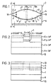
- Figure 1 illustrates in plan view a semiconductor optical device A in accordance with the present invention which, in the described embodiments is fabricated in the InGaAsP material system for use in telecommunication systems with wavelengths centred on 1.3 and 1.55 ⁇ m.
- the device consists of an elongate waveguide region 1 which produces active amplification, formed on a substrate 2.
- the elongate waveguide region 1 has an input 3 at one end for optical radiation and an optical output 4 at its other, second end.
- the input and output 3, 4 are configured to couple onto single mode optical waveguides e.g. optical fibres or alternatively other structures (not shown) integrated onto the substrate.
- the width w of the waveguide region 1 increases progressively from the input 3 in the direction of the length l of the waveguide towards the central or intermediate region 5, from which the width w progressively decreases to the output 4.
- a typical example of the device has a length l of 500 ⁇ m - 1 mm, with the inputs 3 and 4 having a width w of 1 - 2 ⁇ m, and the width w in the intermediate region being of the order of 30 - 40 ⁇ m.
- the waveguide region 1 can be fabricated in a number of different ways and two examples will now be described with reference to Figures 2 to 4.
- FIG 2 shows a schematic cross section taken along the line A-A' of Figure 1 for which the waveguide region 1 is fabricated as a buried heterostructure.
- the waveguide region 1 comprises a layer of active i-InGaAsP material 6 formed on a n-InP layer 7, itself formed on a n-InP substrate 8.
- the active material 6 is overlaid by a p-InP region 9 formed with a conductive over-contact 10 of p-InGaAsP material.
- the general structure of the amplifier, the thicknesses of the various layers and the dopant concentrations, are conventional and reference is directed to A.W. Nelson, W. J. Devlin, R. E. Hobbs, C.G.D. Lenton and S. Wong: "High-power, low-threshold BH lasers operating at 1.52 ⁇ m grown entirely by MOVPE", Electronics Letters, Vol. 21, No. 20, pp 888-889 (26 September 1985).
- the structure is formed from an initial substrate 8 which is formed with layers 6, 7, 9 and 10 over its entire surface in a manner known per se, and material is then selectively etched from the regions shown in dotted outline, using a mask in a manner known per se , the mask having a shape as shown in Figure 1, so as to define the varying width w of the waveguide region along the length thereof.
- p-InP layer 11 and n-InP layer 12 are formed overlying the selectively etched regions by standard MOVPE electric growth techniques.
- An electrically conductive bottom metallisation layer 13 is formed on the underside of the substrate.
- the active material 6 is sandwiched between p-InP region 9 and n-InP layer 7 so that when a voltage is applied between the conductive layer 10 and the bottom layer 13, an electric current passes through the active material 6.
- the polarity of the voltage and the arrangement of the n and p doped layers 11 and 12 is such that in use, they form a reverse-biased junction, with the result that the current is directed selectively through the waveguide region 1 rather than to each side.
- photons incident on input 3 Figure 1 cause electrons to traverse the band gap of the active material 6 so as to generate additional photons, thereby producing optical amplification in the waveguide region.
- the waveguide region has its boundary defined by means of a rib waveguide.
- the device consists of a substrate 14, formed of n-InP material with an overlayer 15 of optically active i-InGaAsP material in a waveguide region 1 shown in dotted outline.
- the layer 15 is overlaid by an etch-stop layer 16 of p-InGaAsP material which is overlaid by a rib 9 of p-InP material, itself covered by a conductive contact region 10 of p-InGaAsP material.
- the layers 9 and 10 are formed in the curved shape shown in Figure 1 by a lithographic mask and selective etching in a similar manner to that described with reference to Figure 2.
- the resulting structure is overlaid with a dielectric material 17, typically silicon dioxide.
- a voltage is applied to the layer 10
- a current is established through the region of layer 15 which is overlaid by the layer 9, so that amplification occurs therein within the region 1 shown in dotted outline. It will be appreciated that the optical confinement produced by the structure shown in Figure 4 is less well defined than with the configuration of Figure 2.
- the single mode optical signal applied to input 3 is thus amplified within the waveguide region 1.
- the single mode expands adiabatically towards the central, intermediate region 5, and is thereafter adiabatically contracted, still in the single mode, and inserted through the output 4 e.g. into an output optical fibre connected thereto (not shown).
- adiabatic we mean no significant coupling into higher order transmission modes.
- the boundaries of waveguide region 1 themselves act to concentrate the amplified light laterally to the output 4, with the advantage that no additional lens structures are required to focus the amplified light into the output optical fibre, as in the prior art .
- the conductive layer 10 is arranged in two portions 10a, 10b that overlie corresponding regions 1a, 1b of the waveguide region 1.
- the current densities in the regions 10a and 10b are selected individually so as to be higher in region 10a than in region 10b, such that amplification primarily occurs in the active material 6 in the region 1a, where the outwardly tapered shape of the region reduces the risk of gain saturation .
- the waveguide region 1 acts to concentrate the resulting amplified light into the output 4 without further significant amplification in the underlying active material 6, so as to minimise the risk of gain saturation.
- the region 10a in this example is fed with a higher current than the region 10b in order to achieve the desired current density differential.
- the conductive layer 10 could be arranged in more than two portions so as to profile the current density spatially through the active material 6 and thereby minimise optical gain saturation.
- anti-reflection coatings are provided on facets 18, 19 for input 3 and output 4.
- the reflectivity needs to be sufficiently low to avoid laser action even at high drive currents, i.e. reflectivity of the order of 0.001 or, preferably, 0.0001.
- one or more of the facets 18, 19 may be left uncoated or one end may be high-reflective coated, so as to produce semi-reflective end regions that promote resonance within the region.
- the uncoated reflectivity is normally around 0.3, and a high-reflectivity coating would produce reflectivities of around 0.9 or higher.
- the device A of Figure 1 is shown with an optical fibre 20 connected to its input, the fibre including a coupler 21 which has a first input port 22 that receives a stream of optical data pulses at a wavelength ⁇ 1 and acts as a first source for the device, and a second input port 23 that receives essentially continuous wave ( cw ) radiation at a second different wavelength ⁇ 2 , the second port 23 acting as a second source for the device A.
- the wavelengths ⁇ 1 , ⁇ 2 are chosen to be within the gain bandwidth of the active material 6 in the waveguide region 1.
- both of the regions 10a,10b are fed with a bias voltage that results in an optical amplification, and the level of amplification in region 1b ( Figure 1), in the absence of ⁇ 1 is close to, but does not exceed the level at which gain-saturation occurs.
- the device A according to the invention has the significant advantage that the waveguide region 1a produces sufficient amplification of the data pulse stream ⁇ 1 and the cross modulation can then occur in region 1b, in an integrated device, thereby providing a very compact and efficient means for producing switching using gain saturation, for use as a modulator. Also, the speed of the cross modulation effect is enhanced by the concentration of light produced in the region 1b, in comparison to a conventional amplifier with an untapered waveguide.
- the output from the device A in Figure 5 is fed through an optical fibre 24 to a bandpass filter 25 tuned to the radiation wavelength ⁇ 2 in order to separate the amplified output signal.
- the device A according to the invention can also be used as in Figure 6 to exploit another non-linear effect.
- an input at wavelength ⁇ 1 can be used to phase shift radiation at a different wavelength ⁇ 2 .
- This effect is exploited in the configuration shown in Figure 6 to achieve phase modulation.
- the input data pulses ⁇ 1 and the cw radiation ⁇ 2 are applied through coupler 26 to the input 3 of the device A through coupler 21, as previously described with reference to Figure 5 and additionally, the cw radiation is fed through the coupler 26 and a variable amplifier or attenuator 27 to be mixed with the output of the device A through a coupler 28.
- the cw radiation ⁇ 2 is phase modulated in the device A by the data pulses ⁇ 1 .
- the resulting phase modulation produced at the output of device A is compared, by means of the coupler 28, with the phase of the cw radiation ⁇ 2 , which acts as a reference, with the result that the output in fibre 24 is amplitude modulated in accordance with the phase modulation that occurs in device A.
- the third wavelength signal ⁇ 3 may be a phase conjugate of the cw radiation ⁇ 2 as described in M.C. Tatham et al, "Compensation of fibre Chromatic Dispersion by Optical Phase Conjugation in a Semiconductor Laser Amplifier", El Lett., 29 pp 1851-2, 1993.
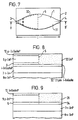
- the specific shape adopted for the waveguide region 1 varies from application to application.
- a symmetrical configuration as shown in Figure 1 is advantageous, with the locus of the boundary of the region 1 conforming to portions of circles, in regions x , y , z dose to the inputs and outputs, and in the intermediate region 5.
- the connecting regions of the boundary, in regions p conform to portions of a parabola.
- the output 4 of the device may include a further non-tapered elongate region (not shown) formed integrally on the substrate, which may include a continuation of the layer 6 of optically active material.
- the active material 6, which produces optical amplification extends over the entire extent of the optical waveguide region 1.
- the active material 6 is disposed solely in a first active portion 30 of the waveguide region 1, and the remaining part of the waveguide 1 constitutes a second, passive portion 31, which is transparent for the relevant wavelength range of light travelling in the waveguide.
- the device can be used advantageously as a high power amplifier, with the passive portion 31 providing an integrated structure for directing the amplified light into the output 4 e.g. to an optical waveguide, without the problem of gain saturation.
- the active and passive portions 30, 31 of the waveguide can be formed in a number of different ways. Referring now to Figure 8, this shows a section taken along B-B' of Figure 7 according to a first structure.
- the general structure is similar to that shown in Figure 2.
- the waveguide region 1 is defined by an additional layer 32 of InGaAsP material, which has a bandgap selected so that it is transparent to the amplified optical radiation and is hence passive.
- the optically active material is provided as the layer 6 which, as previously described, is formed of i-InGaAsP material, but in this embodiment, overlies the layer 32 solely in the active portion 30. The layer 6 thus produces amplification of light travelling in the waveguide.
- the layer 6 is sandwiched between a p-InP layer 9 and a n-InP layer 7, with a conductive over-contact 10 of p-InGaAsP material.
- the layers 32, 6, 9 and 10 are formed as continuous layers over the entire surface area and then the layers 6, 9 and 10 are selectively etched from the passive portion, and replaced by a cladding region 33 of i-InP material, which is grown in its place. The resulting configuration is then selectively masked and etched to provide the curved waveguide boundary, as described with reference to Figures 1 and 2.
- the active layer 6 was formed 0.15 ⁇ m thick with a bandgap of about 1.55 ⁇ m and the layer 32 had a thickness of 0.4 ⁇ m and a bandgap of 1.1 ⁇ m.
- the waveguide may be formed as a ridge structure, by forming the layer 32 as a continuous layer, and forming a ridge from the layers 6, 9, 10 and 33 according to general techniques disclosed in Sherlock, G., Burton, J., Fiddyment, P., Sully, P., Kelly, A., and Robertson M. "An Integrated 2x2 Optical Switch with Gain", Electronics Letters 30 (1994), pp 137-8.
- the passive layer 32 is omitted.
- the layers 6, 9 and 10 are selectively etched and then a passive layer 34 of InGaAsP is grown so as to form a continuation of the layer 6, as a heterolayer.
- the layer 34 typically chosen to have a bandgap of 1.3 ⁇ m when the device is to operate at 1.5 ⁇ m.
- the layer 34 can be grown by metal-organic vapour phase epitaxy (MOVPE). By this technique, the layers 6 and 34 can be formed with an optical quality waveguide junction at which no significant reflection occurs.
- MOVPE metal-organic vapour phase epitaxy
- MOVPE Metal-organic chemical vapor deposition
- the embodiments shown in Figure 7 to 9 have the advantage that amplification can occur in the active portion without significant gain saturation, due to the increasing width of the active portion 30 along the length of the device and that, the resulting amplified light can then be concentrated within the waveguide region 1 by the action of its boundary, so as to be directed to the output 4 without problems of saturation effects due to gain saturation, as a result of the passive nature of portion 31 of the waveguide, and without the need for additional separate lens structures.
- optical radiation includes visible and non-visible radiation such as ultra-violet and infra-red.
Landscapes
- Physics & Mathematics (AREA)
- Condensed Matter Physics & Semiconductors (AREA)
- General Physics & Mathematics (AREA)
- Electromagnetism (AREA)
- Optics & Photonics (AREA)
- Semiconductor Lasers (AREA)
- Optical Integrated Circuits (AREA)
- Lasers (AREA)
Claims (23)
- Halbleitervorrichtung mit einem optischen Eingang (3), einem optischen Ausgang (4) und einem länglichen Wellenleitbereich (1), der sich von dem optischen Eingang (3) über einen mittleren Bereich (5) bis zu dem optischen Ausgang (4) erstreckt, wobei zumindest ein Teil dieses Wellenleitbereichs (1) aus aktivem Material (6) gefertigt ist, welches zum Verstärken darin durchlaufender optische Signale ausgebildet ist, wobei dieser längliche Wellenleitbereich (1) mit einem leitfähigen Kontakt (10) überzogen ist, um einen Bias-Strom an das aktive Material (6) anzulegen; wobei die Halbleitervorrichtung dadurch gekennzeichnet ist, dass der Wellenleitbereich (1) einen sich erweiternden Bereich, in dem die Breite des Wellenleitbereichs (1) progressiv von dem optischen Eingang (3) bis zu dem mittleren Bereich (5) zunimmt, und einen sich verengenden Bereich umfasst, in dem die Breite des Wellenleitbereichs (1) progressiv von dem mittleren Bereich (5) bis zu dem optischen Ausgang (4) abnimmt, wodurch in dem sich erweiternden Bereich des Wellenleitbereichs (1) verstärktes Licht in dem sich verengenden Bereich des Wellenleitbereichs (1) konzentriert und dadurch an dem optischen Ausgang (4) gebündelt wird.
- Vorrichtung nach Anspruch 1, in welcher der leitfähige Kontakt (10) in einen ersten Teil (10a), der den sich erweiternden Bereich des Wellenleitbereichs (1) überzieht, und einen zweiten Teil (10b) aufgeteilt ist, der den sich verengenden Bereich des Wellenleitbereichs (1) überzieht, wodurch unterschiedliche Pegel von Bias-Strom über die sich erweiternden und verengenden Bereiche des Wellenleitbereichs (1) angelegt werden können.
- Halbleitervorrichtung nach Anspruch 1, in welcher der sich erweiternde Bereich des Wellenleitbereichs (1) aus dem aktiven Material (6) und der sich verengende Bereich des Wellenleitbereichs (1) aus passivem Material (34) gefertigt ist, das für darin durchlaufende optische Signale transparent ist.
- Vorrichtung nach einem der vorhergehenden Ansprüche, in welcher die Zunahmerate der Breite (w) in dem sich erweiternden Bereich des Wellenleitbereichs (1) und die Abnahmerate der Breite (w) in dem sich verengenden Bereich des Wellenleitbereichs (1) über die Länge (1) des Wellenleitbereichs (1) variieren.
- Vorrichtung nach Anspruch 4, in welcher der Grenzbereich des Wellenleitbereichs in dem mittleren Bereich (5) eine parabolische Form aufweist und dieser Grenzbereich sich an Teile von Kreisbögen (x, y, z) zwischen dem parabolischen mittleren Bereich (5) und sowohl dem optischen Eingang (3) als auch dem optischen Ausgang (4) anpasst.
- Vorrichtung nach Anspruch 5, in welcher die Form des Grenzbereichs auf beiden Seiten des mittleren Bereichs (5) symmetrisch ist.
- Vorrichtung nach einem der vorhergehenden Ansprüche, welche auch eine erste optische Quelle (22) und eine zweite optische Quelle (23) aufweist, die beide mit dem optischen Eingang (3) verbunden sind, wobei die erste optische Quelle (22) eingerichtet ist, optische Datenimpulse mit einer ersten Wellenlänge (λ1) zu liefern und die zweite optische Quelle (23) eingerichtet ist, optische Strahlung mit kontinuierlicher Welle (cw) mit einer zweiten unterschiedlichen Wellenlänge (λ2) zu liefern.
- Vorrichtung nach Anspruch 7, in welcher die cw-Strahlung von der zweiten optischen Quelle (23) und die Datenimpulse der ersten optischen Quelle (22) sich derart gegenseitig beeinflussen, dass sie eine Verstärkungssättigung in dem aktiven Material erzeugen, wodurch die Strahlung von der zweiten Quelle von den Datenimpulsen moduliert wird.
- Vorrichtung nach Anspruch 7 oder 8, wobei ein Filter (25) an den Ausgang des Wellenleitbereichs (1) gekoppelt ist, um vorzugsweise die modulierte Strahlung mit der zweiten Wellenlänge durchzulassen.
- Vorrichtung nach einem der Ansprüche 7, 8 oder 9, welche auch Kopplungsmittel (21) zum Koppeln sowohl der ersten Quelle (22) als auch der zweiten Quelle (23) mit dem Eingang (3) des Wellenleitbereichs (1) umfasst.
- Vorrichtung nach einem der Ansprüche 7 bis 10, in welcher die Strahlungen von den Quellen sich gegenseitig beeinflussen, wodurch die Strahlung von der zweiten optischen Quelle (23) von den Datenimpulsen der ersten optischen Quelle (22) moduliert wird.
- Vorrichtung nach Anspruch 11 mit Phasenauswertungsmitteln (27, 28), die an den Ausgang (4) des Wellenleitbereichs (1) gekoppelt sind, um die phasenmodulierten Signale mit der Phase von Signalen von dem Ausgang zu vergleichen.
- Vorrichtung nach einem der Ansprüche 7 bis 12, in welcher die Strahlungen von der ersten und zweiten Quelle sich gegenseitig beeinflussen, um eine Strahlung an dem Ausgang (4) zu erzeugen, die eine andere Wellenlänge als die der Strahlung von der zweiten Quelle und den Datenimpulsen von der ersten Quelle aufweist.
- Vorrichtung nach Anspruch 13 mit Filtermitteln (25), die an den Ausgang (4) des Wellenleitbereichs (1) gekoppelt sind und selektiv auf die unterschiedliche Wellenlänge an dem Ausgang reagieren.
- Vorrichtung nach einem der vorhergehenden Ansprüche mit Antireflexbelägen an dem Eingang (3) und dem Ausgang (4).
- Vorrichtung nach einem der vorhergehenden Ansprüche, in welcher der Wellenleitbereich eine Rippen-Wellenleiterstruktur (9, 10) aufweist.
- Vorrichtung nach einem der vorhergehenden Ansprüche, in welcher der aktive Bereich eine eingebettete (buried) Heterostruktur (BH) (6) auf einem Substrat (2) aufweist.
- Vorrichtung nach Anspruch 17, in welcher das aktive Material (6) eine Schicht aus InGaAsP aufweist, die zwischen einer Schicht (7) aus InP eines ersten Typs einer elektrischen Leitfähigkeit und einem Bereich (9) aus InP eines zweiten Typs einer elektrischen Leitfähigkeit angeordnet ist.
- Vorrichtung nach Anspruch 18 mit einer Schicht (14) aus InP eines ersten Typs einer elektrischen Leitfähigkeit, die von einer Schicht aus i-InGaAsP (15) überlagert wird, welche das aktive Material umfasst, wobei diese Schicht (15) überlagert wird von einer Schicht (16) aus InGaAsP eines zweiten Typs einer elektrischen Leitfähigkeit und einem darüber liegenden Streifen (9) aus InP mit einer Konfiguration, welche den Grenzbereich dieses Wellenleitbereichs (1) in der i-InGaAsP-Schicht definiert.
- Vorrichtung nach einem der vorhergehenden Ansprüche, in welcher der aktive Bereich eine eingebettete (buried) Heterostruktur (BH) (6) auf einem Substrat (2) aufweist.
- Vorrichtung nach Anspruch 20, in welcher das aktive Material (6) eine Schicht aus InGaAsP aufweist, die zwischen einer Schicht (7) aus InP eines ersten Typs einer elektrischen Leitfähigkeit und einem Bereich (9) aus InP eines zweiten Typs einer elektrischen Leitfähigkeit angeordnet ist.
- Vorrichtung nach einem der Ansprüche 1 bis 19, in welcher der Wellenleitbereich eine Rippen-Wellenleiterstruktur (9, 10) aufweist.
- Vorrichtung nach Anspruch 21 mit einer Schicht (14) aus InP eines ersten Typs einer elektrischen Leitfähigkeit, die von einer Schicht aus i-InGaAsP (15) überlagert wird, welche das aktive Material umfasst, wobei diese Schicht (15) überlagert wird von einer Schicht (16) aus InGaAsP eines zweiten Typs einer elektrischen Leitfähigkeit und einem darüber liegenden Streifen (9) aus InP mit einer Konfiguration, welche der Grenzbereich dieses Wellenleitbereichs (1) in der i-InGaAsP-Schicht definiert.
Priority Applications (1)
| Application Number | Priority Date | Filing Date | Title |
|---|---|---|---|
| EP95931340A EP0781465B1 (de) | 1994-09-14 | 1995-09-14 | Optische vorrichtung |
Applications Claiming Priority (6)
| Application Number | Priority Date | Filing Date | Title |
|---|---|---|---|
| EP94306753 | 1994-09-14 | ||
| EP94306753 | 1994-09-14 | ||
| GB9425729 | 1994-12-20 | ||
| GBGB9425729.2A GB9425729D0 (en) | 1994-09-14 | 1994-12-20 | Otical device |
| PCT/GB1995/002191 WO1996009668A1 (en) | 1994-09-14 | 1995-09-14 | Optical device |
| EP95931340A EP0781465B1 (de) | 1994-09-14 | 1995-09-14 | Optische vorrichtung |
Publications (2)
| Publication Number | Publication Date |
|---|---|
| EP0781465A1 EP0781465A1 (de) | 1997-07-02 |
| EP0781465B1 true EP0781465B1 (de) | 2003-11-05 |
Family
ID=26137289
Family Applications (1)
| Application Number | Title | Priority Date | Filing Date |
|---|---|---|---|
| EP95931340A Expired - Lifetime EP0781465B1 (de) | 1994-09-14 | 1995-09-14 | Optische vorrichtung |
Country Status (7)
| Country | Link |
|---|---|
| US (1) | US5917972A (de) |
| EP (1) | EP0781465B1 (de) |
| JP (1) | JP3895370B2 (de) |
| CA (1) | CA2199510C (de) |
| DE (1) | DE69532083T2 (de) |
| GB (1) | GB9425729D0 (de) |
| WO (1) | WO1996009668A1 (de) |
Families Citing this family (27)
| Publication number | Priority date | Publication date | Assignee | Title |
|---|---|---|---|---|
| FR2760850B1 (fr) * | 1997-03-13 | 1999-04-16 | Alsthom Cge Alcatel | Procede de fabrication de circuits optiques integres permettant de minimiser les pertes optiques de couplage |
| JP3244114B2 (ja) * | 1997-08-18 | 2002-01-07 | 日本電気株式会社 | 半導体光アンプ |
| FR2768524B1 (fr) * | 1997-09-12 | 1999-10-22 | France Telecom | Amplificateur a large surface avec recombineur a interferences multimodes |
| JP3045115B2 (ja) * | 1997-09-30 | 2000-05-29 | 日本電気株式会社 | 光半導体装置の製造方法 |
| US6034380A (en) * | 1997-10-07 | 2000-03-07 | Sarnoff Corporation | Electroluminescent diode with mode expander |
| FR2770938B1 (fr) * | 1997-11-10 | 1999-12-10 | Alsthom Cge Alcatel | Amplificateur optique semi-conducteur et source laser integree l'incorporant |
| US6819687B1 (en) * | 1997-12-10 | 2004-11-16 | Nellcor Puritan Bennett Incorporated | Non-imaging optical corner turner |
| FR2779838B1 (fr) * | 1998-06-15 | 2000-08-04 | Alsthom Cge Alcatel | Composant optique a semiconducteur et amplificateur et convertisseur de longueurs d'onde constitues par ce composant |
| FR2786278B1 (fr) * | 1998-11-24 | 2001-01-26 | Cit Alcatel | Composant optique a semi-conducteur comportant un adapteur de mode |
| US6614585B1 (en) | 1999-05-06 | 2003-09-02 | Trumpf Photonics Inc. | Phase conjugating structure for mode matching in super luminescent diode cavities |
| SE9902916L (sv) * | 1999-08-16 | 2001-02-17 | Ericsson Telefon Ab L M | Modulator och integrerad krets |
| CA2404451A1 (en) * | 2000-02-25 | 2001-08-30 | Princeton Lightwave, Inc. | Multi-pass, arcuate bent waveguide, high power superluminescent diode |
| SE521023C2 (sv) * | 2000-07-07 | 2003-09-23 | Ericsson Telefon Ab L M | Optisk anordning samt framställning därav |
| IES20000820A2 (en) * | 2000-10-11 | 2002-05-29 | Nat Univ Ireland | A single frequency laser |
| US20020176152A1 (en) * | 2001-05-04 | 2002-11-28 | Paola Parolari | Intensity modulation of optical signals |
| KR100393193B1 (ko) * | 2001-09-29 | 2003-07-31 | 삼성전자주식회사 | 광 도파로와 mems 액추에이터를 구비한 가변 광 감쇠기 |
| KR100446524B1 (ko) * | 2002-11-25 | 2004-09-04 | 삼성전자주식회사 | 파장분할 다중화/역다중화기 |
| EP1624325B1 (de) * | 2004-08-03 | 2013-05-22 | STMicroelectronics Srl | Integrierte optische Struktur, empfindlich auf die in den Mantel eines planaren Lichtwellenleiterschaltkreises abgestrahlte Energie |
| EP1840607B1 (de) * | 2005-01-20 | 2013-11-06 | Fujitsu Ltd. | Optisches wellenleiterbauelement und halbleiterbauelement |
| US8615029B2 (en) * | 2009-12-30 | 2013-12-24 | Ipg Photonics Corporation | Optical device |
| US10758886B2 (en) | 2015-09-14 | 2020-09-01 | Arizona Board Of Regents On Behalf Of Arizona State University | Conditioned surfaces for in situ molecular array synthesis |
| JP2019526786A (ja) | 2016-06-20 | 2019-09-19 | ヘルステル・インコーポレイテッドHealthtell Inc. | 自己免疫疾患の診断および処置のための方法 |
| KR20190020106A (ko) | 2016-06-20 | 2019-02-27 | 헬스텔 인크. | 자가면역 질환의 차별적 진단 방법 |
| WO2018045300A1 (en) * | 2016-09-01 | 2018-03-08 | Luxtera, Inc. | Method and system for a vertical junction high-speed phase modulator |
| CN110168370A (zh) | 2016-11-11 | 2019-08-23 | 健康之语公司 | 用于鉴定候选生物标志物的方法 |
| CN110537302B (zh) * | 2017-04-04 | 2021-06-15 | 三菱电机株式会社 | 半导体装置、半导体装置的制造方法 |
| CN118140367A (zh) * | 2021-09-23 | 2024-06-04 | 自由光子学有限责任公司 | 用于半导体激光器和光放大器的电流控制的分段接触 |
Family Cites Families (13)
| Publication number | Priority date | Publication date | Assignee | Title |
|---|---|---|---|---|
| JPS5850790A (ja) * | 1981-09-19 | 1983-03-25 | Mitsubishi Electric Corp | 光半導体デバイス |
| JPS59154089A (ja) * | 1983-02-22 | 1984-09-03 | Sony Corp | 半導体レ−ザ− |
| FR2598862B1 (fr) * | 1986-05-16 | 1994-04-08 | Bouley Jean Claude | Laser a semi-conducteur a reaction distribuee et a longueur d'onde continument accordable. |
| US4815084A (en) * | 1987-05-20 | 1989-03-21 | Spectra Diode Laboratories, Inc. | Semiconductor laser with integrated optical elements |
| JPH03284892A (ja) * | 1990-03-30 | 1991-12-16 | Fujitsu Ltd | 光増幅装置 |
| JP2839699B2 (ja) * | 1990-11-08 | 1998-12-16 | 株式会社東芝 | 進行波型光増幅器 |
| US5140651A (en) * | 1991-06-27 | 1992-08-18 | The United States Of America As Represented By The Secretary Of The Air Force | Semiconductive guided-wave programmable optical delay lines using electrooptic fabry-perot elements |
| US5179568A (en) * | 1991-08-28 | 1993-01-12 | The United States Of America As Represented By The United States National Aeronautics And Space Administration | Self-collimated unstable resonator semiconductor laser |
| US5392308A (en) * | 1993-01-07 | 1995-02-21 | Sdl, Inc. | Semiconductor laser with integral spatial mode filter |
| DE4322164A1 (de) * | 1993-07-03 | 1995-01-12 | Ant Nachrichtentech | Optoelektronisches Bauelement mit Rückkopplungsgitter, mit axial quasi-kontinuierlich und nahezu beliebig variierbarem Gitterkopplungs-Koeffizienten, mit quasi-kontinuierlich axial verteilbarer Brechungsindex-Variation, sowie mit axial nahezu beliebig verteilbarer und variierbarer Phasenverschiebung |
| FR2709566B1 (fr) * | 1993-09-02 | 1995-09-29 | Alcatel Nv | Composant optique actif semiconducteur à ruban. |
| US5517517A (en) * | 1994-06-30 | 1996-05-14 | At&T Corp. | Semiconductor laser having integrated waveguiding lens |
| BR0206919A (pt) * | 2001-02-02 | 2004-07-06 | Conjuchem Inc | Derivados de fator de liberação de hormÈnio de crescimento de longa duração |
-
1994
- 1994-12-20 GB GBGB9425729.2A patent/GB9425729D0/en active Pending
-
1995
- 1995-09-14 WO PCT/GB1995/002191 patent/WO1996009668A1/en active IP Right Grant
- 1995-09-14 DE DE69532083T patent/DE69532083T2/de not_active Expired - Lifetime
- 1995-09-14 JP JP51066996A patent/JP3895370B2/ja not_active Expired - Fee Related
- 1995-09-14 EP EP95931340A patent/EP0781465B1/de not_active Expired - Lifetime
- 1995-09-14 CA CA002199510A patent/CA2199510C/en not_active Expired - Fee Related
- 1995-09-14 US US08/809,130 patent/US5917972A/en not_active Expired - Lifetime
Also Published As
| Publication number | Publication date |
|---|---|
| DE69532083T2 (de) | 2004-08-26 |
| CA2199510C (en) | 2001-02-20 |
| CA2199510A1 (en) | 1996-03-28 |
| JP3895370B2 (ja) | 2007-03-22 |
| US5917972A (en) | 1999-06-29 |
| DE69532083D1 (de) | 2003-12-11 |
| JPH10505954A (ja) | 1998-06-09 |
| EP0781465A1 (de) | 1997-07-02 |
| GB9425729D0 (en) | 1995-02-22 |
| WO1996009668A1 (en) | 1996-03-28 |
Similar Documents
| Publication | Publication Date | Title |
|---|---|---|
| EP0781465B1 (de) | Optische vorrichtung | |
| EP0735635B1 (de) | Optischer Halbleitervorrichtung, Antriebsverfahren und optisches Kommunikationssystem | |
| EP0721240B1 (de) | Polarisationsmodenselektiver Halbleiterlaser, Modulationsverfahren und optisches Kommunikationssystem unter Verwendung dieses Lasers | |
| US5539571A (en) | Differentially pumped optical amplifer and mopa device | |
| US4885753A (en) | Semiconductor laser device of variable wavelength type | |
| EP0624284B1 (de) | Mit resonatorbegrenzenden nuten versehene konische verstärkungsanordnung für halbleiterlaser | |
| US6252895B1 (en) | Distributed feedback semiconductor laser in which light intensity distributions differ in different polarization modes, and driving method therefor | |
| EP0345923A2 (de) | Gitter-Koppler mit monolithisch integriertem Quantum-Well-Index-Modulator | |
| US5859866A (en) | Photonic integration using a twin waveguide structure | |
| EP0300790B1 (de) | Halbleiterlaser | |
| JPH05218385A (ja) | 光半導体装置、その駆動方法及びそれを用いた光伝送方式 | |
| US5103455A (en) | Monolithically integrated semiconductor optical preamplifier | |
| US5822352A (en) | Optical semiconductor apparatus, fabrication method thereof, modulation method therefor, light source apparatus and optical communication system using the same | |
| US6224667B1 (en) | Method for fabricating semiconductor light integrated circuit | |
| JP2003046190A (ja) | 半導体レーザ | |
| US6337868B1 (en) | Distributed feedback semiconductor laser and a driving method therefor | |
| CA2014937C (en) | Laser-photodetector assemblage | |
| JPH09121072A (ja) | 集積光電子構成部品 | |
| JP2708467B2 (ja) | 波長可変半導体レーザ | |
| EP0197084B1 (de) | Injektionslaserstruktur mit niedrigem rauschen | |
| US7065300B1 (en) | Optical transmitter including a linear semiconductor optical amplifier | |
| EP0444607B1 (de) | Optisches Wellenleiterelement und Verfahren zum Betreiben desselben | |
| EP1677395B1 (de) | Optische Verstärkungsvorrichtung | |
| US5675602A (en) | Optical integrated circuit device and driving method therefor | |
| JP3246703B2 (ja) | 偏波変調可能な半導体レーザおよびこれを用いた光通信方式 |
Legal Events
| Date | Code | Title | Description |
|---|---|---|---|
| PUAI | Public reference made under article 153(3) epc to a published international application that has entered the european phase |
Free format text: ORIGINAL CODE: 0009012 |
|
| 17P | Request for examination filed |
Effective date: 19970226 |
|
| AK | Designated contracting states |
Kind code of ref document: A1 Designated state(s): DE ES FR GB IT NL PT |
|
| 17Q | First examination report despatched |
Effective date: 19971120 |
|
| GRAH | Despatch of communication of intention to grant a patent |
Free format text: ORIGINAL CODE: EPIDOS IGRA |
|
| RIC1 | Information provided on ipc code assigned before grant |
Ipc: 7H 01S 5/10 B Ipc: 7H 01S 5/02 B Ipc: 7H 01S 5/40 A |
|
| GRAS | Grant fee paid |
Free format text: ORIGINAL CODE: EPIDOSNIGR3 |
|
| GRAA | (expected) grant |
Free format text: ORIGINAL CODE: 0009210 |
|
| AK | Designated contracting states |
Kind code of ref document: B1 Designated state(s): DE ES FR GB IT NL PT |
|
| PG25 | Lapsed in a contracting state [announced via postgrant information from national office to epo] |
Ref country code: NL Free format text: LAPSE BECAUSE OF FAILURE TO SUBMIT A TRANSLATION OF THE DESCRIPTION OR TO PAY THE FEE WITHIN THE PRESCRIBED TIME-LIMIT Effective date: 20031105 Ref country code: IT Free format text: LAPSE BECAUSE OF FAILURE TO SUBMIT A TRANSLATION OF THE DESCRIPTION OR TO PAY THE FEE WITHIN THE PRE;WARNING: LAPSES OF ITALIAN PATENTS WITH EFFECTIVE DATE BEFORE 2007 MAY HAVE OCCURRED AT ANY TIME BEFORE 2007. THE CORRECT EFFECTIVE DATE MAY BE DIFFERENT FROM THE ONE RECORDED.SCRIBED TIME-LIMIT Effective date: 20031105 |
|
| REG | Reference to a national code |
Ref country code: GB Ref legal event code: FG4D |
|
| REF | Corresponds to: |
Ref document number: 69532083 Country of ref document: DE Date of ref document: 20031211 Kind code of ref document: P |
|
| PG25 | Lapsed in a contracting state [announced via postgrant information from national office to epo] |
Ref country code: ES Free format text: LAPSE BECAUSE OF FAILURE TO SUBMIT A TRANSLATION OF THE DESCRIPTION OR TO PAY THE FEE WITHIN THE PRESCRIBED TIME-LIMIT Effective date: 20040216 |
|
| NLV1 | Nl: lapsed or annulled due to failure to fulfill the requirements of art. 29p and 29m of the patents act | ||
| ET | Fr: translation filed | ||
| PLBE | No opposition filed within time limit |
Free format text: ORIGINAL CODE: 0009261 |
|
| STAA | Information on the status of an ep patent application or granted ep patent |
Free format text: STATUS: NO OPPOSITION FILED WITHIN TIME LIMIT |
|
| 26N | No opposition filed |
Effective date: 20040806 |
|
| PG25 | Lapsed in a contracting state [announced via postgrant information from national office to epo] |
Ref country code: PT Free format text: LAPSE BECAUSE OF NON-PAYMENT OF DUE FEES Effective date: 20040405 |
|
| REG | Reference to a national code |
Ref country code: GB Ref legal event code: 732E |
|
| REG | Reference to a national code |
Ref country code: FR Ref legal event code: TP |
|
| PGFP | Annual fee paid to national office [announced via postgrant information from national office to epo] |
Ref country code: GB Payment date: 20090922 Year of fee payment: 15 |
|
| PGFP | Annual fee paid to national office [announced via postgrant information from national office to epo] |
Ref country code: DE Payment date: 20090922 Year of fee payment: 15 |
|
| GBPC | Gb: european patent ceased through non-payment of renewal fee |
Effective date: 20100914 |
|
| REG | Reference to a national code |
Ref country code: FR Ref legal event code: ST Effective date: 20110531 |
|
| REG | Reference to a national code |
Ref country code: DE Ref legal event code: R119 Ref document number: 69532083 Country of ref document: DE Effective date: 20110401 |
|
| PG25 | Lapsed in a contracting state [announced via postgrant information from national office to epo] |
Ref country code: FR Free format text: LAPSE BECAUSE OF NON-PAYMENT OF DUE FEES Effective date: 20100930 Ref country code: DE Free format text: LAPSE BECAUSE OF NON-PAYMENT OF DUE FEES Effective date: 20110401 |
|
| PG25 | Lapsed in a contracting state [announced via postgrant information from national office to epo] |
Ref country code: GB Free format text: LAPSE BECAUSE OF NON-PAYMENT OF DUE FEES Effective date: 20100914 |
|
| PGFP | Annual fee paid to national office [announced via postgrant information from national office to epo] |
Ref country code: FR Payment date: 20091001 Year of fee payment: 15 |