EP0780956B1 - Dauermagnetläufer für Klauenpolschrittmotor - Google Patents
Dauermagnetläufer für Klauenpolschrittmotor Download PDFInfo
- Publication number
- EP0780956B1 EP0780956B1 EP96203403A EP96203403A EP0780956B1 EP 0780956 B1 EP0780956 B1 EP 0780956B1 EP 96203403 A EP96203403 A EP 96203403A EP 96203403 A EP96203403 A EP 96203403A EP 0780956 B1 EP0780956 B1 EP 0780956B1
- Authority
- EP
- European Patent Office
- Prior art keywords
- rotor
- permanent magnet
- stator
- axial
- claw
- Prior art date
- Legal status (The legal status is an assumption and is not a legal conclusion. Google has not performed a legal analysis and makes no representation as to the accuracy of the status listed.)
- Expired - Lifetime
Links
- 238000006073 displacement reaction Methods 0.000 claims description 9
- 230000005672 electromagnetic field Effects 0.000 claims description 2
- 210000000078 claw Anatomy 0.000 description 11
- 230000004907 flux Effects 0.000 description 4
- 230000008878 coupling Effects 0.000 description 3
- 238000010168 coupling process Methods 0.000 description 3
- 238000005859 coupling reaction Methods 0.000 description 3
- 230000004323 axial length Effects 0.000 description 2
- 238000006243 chemical reaction Methods 0.000 description 2
- 238000004519 manufacturing process Methods 0.000 description 2
- 239000000696 magnetic material Substances 0.000 description 1
- 238000004804 winding Methods 0.000 description 1
Images
Classifications
-
- H—ELECTRICITY
- H02—GENERATION; CONVERSION OR DISTRIBUTION OF ELECTRIC POWER
- H02K—DYNAMO-ELECTRIC MACHINES
- H02K7/00—Arrangements for handling mechanical energy structurally associated with dynamo-electric machines, e.g. structural association with mechanical driving motors or auxiliary dynamo-electric machines
- H02K7/06—Means for converting reciprocating motion into rotary motion or vice versa
-
- H—ELECTRICITY
- H02—GENERATION; CONVERSION OR DISTRIBUTION OF ELECTRIC POWER
- H02K—DYNAMO-ELECTRIC MACHINES
- H02K37/00—Motors with rotor rotating step by step and without interrupter or commutator driven by the rotor, e.g. stepping motors
- H02K37/10—Motors with rotor rotating step by step and without interrupter or commutator driven by the rotor, e.g. stepping motors of permanent magnet type
- H02K37/12—Motors with rotor rotating step by step and without interrupter or commutator driven by the rotor, e.g. stepping motors of permanent magnet type with stationary armatures and rotating magnets
- H02K37/14—Motors with rotor rotating step by step and without interrupter or commutator driven by the rotor, e.g. stepping motors of permanent magnet type with stationary armatures and rotating magnets with magnets rotating within the armatures
-
- H—ELECTRICITY
- H02—GENERATION; CONVERSION OR DISTRIBUTION OF ELECTRIC POWER
- H02K—DYNAMO-ELECTRIC MACHINES
- H02K37/00—Motors with rotor rotating step by step and without interrupter or commutator driven by the rotor, e.g. stepping motors
- H02K37/24—Structural association with auxiliary mechanical devices
Definitions
- the invention relates to a claw pole stepper motor with a stator has at least two stator yoke elements delimited by outer edges, in which are each arranged at least one stator coil, and with one Rotor having permanent magnets, which by means of at least one axial bearing in is mounted in the axial direction, wherein the rotor has an internal thread in which a threaded bolt can be stored.
- Such a claw pole stepper motor is known from EP 550 102 A2.
- Claw pole stepper motors have no end windings and the stator turns on both axial ends by a stator yoke, e.g. a stator sheet, limited. Therefore, in such a known claw pole stepper motor axial length of the permanent magnet of the rotor less than or equal to the axial Distance between the outer edges of the stator yoke elements to the amount of to limit permanent magnetic material to a minimum.
- the Threaded bolt secured against rotational movement, so one Rotational movement of the rotor in an axial movement of the threaded bolt transfer. If the threaded bolt is e.g.
- the axial extension of the permanent magnet of the rotor over the assigned one The outer edge of the stator yoke element also has the result that an axial Displacement of the rotor that is not greater than the axial extension of the The rotor is permanent magnet, no reduction in electromagnetic Coupling of the flux generated by the stator coils with the rotor and thus no reduction in torque.
- This will make it possible To design claw pole stepper motor with simpler bearings, the lower one have axial rigidity, as well as the requirements for the mechanical Manufacturing accuracy of the claw pole stepper motor and the components of the To reduce claw pole stepper motor. These measures lead to a significant cost reduction, while the axial extension of the Permanent magnets of the rotor over the outer edge of the stator yoke element causes only minor additional costs.
- An advantageous embodiment of the invention is characterized in that the Permanent magnet of the rotor by at least 5% of the total length of the Permanent magnet of the rotor over the assigned outer edge of the Stator yoke element protrudes.
- a further advantageous embodiment of the invention is characterized in that that the permanent magnet of the rotor at both axial ends via the associated Protrudes the outer edge of the stator yoke element.
- the permanent magnet of the rotor If the permanent magnet of the rotor is axially extended on both sides, it can exert both a compressive force and a pulling force on an actuator without an axial displacement due to the bearing tolerances a reduction in Torque due to a lower flux linkage of the stator with the rotor causes.
- a further advantageous embodiment of the invention is characterized in that that the permanent magnet of the rotor at both axial ends by at least 5% the total length of the permanent magnet of the rotor over the respectively assigned Protrudes the outer edge of the stator yoke element.
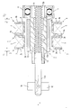
- the only figure in the drawing shows a claw pole stepper motor with a stator 1 and a rotor 2.
- the stator 1 has a first stator yoke element 3 and second stator yoke element 4.
- the first stator yoke element 3 has a first stator plate 3a and a second stator plate 3b.
- the second Stator return element 4 has a third stator plate 4a and a fourth stator plate 4b.
- a first stator coil is located in the first stator yoke element 3 5.
- the first stator yoke element 3 is delimited by a first outer edge 7, the second stator yoke element 4 is supported by a second outer edge 8 limited.
- the rotor 2 has a permanent magnet 10 with a first axial end 10a and a second axial end 10b.
- the axial ends 10a and 10b of the permanent magnet 10 protrude beyond the associated outer edges 7 and 8 of the stator yoke elements 3 and 4 by a distance S 1 and S 2 .
- the rotor 2 is supported by means of an axial bearing 11.
- the rotor 2 has an internal thread 12 in which a threaded bolt 13 is mounted.
- the threaded bolt 13 consists of a first section 13a, which is designed without a thread, and a section 13b, which has a thread 14.
- the thread 14 of the threaded bolt 13 engages in the internal thread 12 of the rotor 2.
- the threaded bolt 13 is secured against rotation by means of a bearing part 16.
- a bearing part 16 This is possible, for example, by the fact that the interior of the bearing part 16 is square in a manner not shown in detail and that a portion 13c of the first portion 13a of the threaded bolt 13 is also square and is fitted into the square interior of the bearing part 16. The result of this is that a rotational movement of the rotor 2 is converted into an axial movement of the threaded bolt 13 in the positive or negative X direction.
- the threaded bolt 13 If the threaded bolt 13 is moved, for example, in the positive X direction and if it has to exert a force during this axial movement in the positive X direction, for example in order to actuate an actuator, then a reactive force acts on the threaded bolt 13 in the negative X direction, which must be caught by the thrust bearing 11.
- this axial displacement of the rotor 2 in the negative X direction has no reduction in the electromagnetic coupling of the electromagnetic flux generated by the stator coils 5 and 6 with the permanent magnet 10 of the rotor 22, as long as this axial displacement in the negative X direction is smaller than the distance S 1 by which the permanent magnet 10 projects beyond the outer edge 7 of the stator 1.
- the bearing play of the axial bearing 11 can be chosen to be as large as the distance S 1 without there being a reduction in the torque of the claw-pole stepping motor.
- Stator 1 thrust bearing 11 and bearing part 16 are in a manner not shown in one Not shown housing of the claw pole stepper motor arranged.
Landscapes
- Engineering & Computer Science (AREA)
- Power Engineering (AREA)
- Iron Core Of Rotating Electric Machines (AREA)
- Permanent Field Magnets Of Synchronous Machinery (AREA)
- Connection Of Motors, Electrical Generators, Mechanical Devices, And The Like (AREA)
- Permanent Magnet Type Synchronous Machine (AREA)
- Magnetic Treatment Devices (AREA)
Applications Claiming Priority (2)
| Application Number | Priority Date | Filing Date | Title |
|---|---|---|---|
| DE19547895 | 1995-12-21 | ||
| DE19547895A DE19547895A1 (de) | 1995-12-21 | 1995-12-21 | Klauenpolschrittmotor mit einem Stator |
Publications (2)
| Publication Number | Publication Date |
|---|---|
| EP0780956A1 EP0780956A1 (de) | 1997-06-25 |
| EP0780956B1 true EP0780956B1 (de) | 1999-06-30 |
Family
ID=7780854
Family Applications (1)
| Application Number | Title | Priority Date | Filing Date |
|---|---|---|---|
| EP96203403A Expired - Lifetime EP0780956B1 (de) | 1995-12-21 | 1996-12-02 | Dauermagnetläufer für Klauenpolschrittmotor |
Country Status (6)
| Country | Link |
|---|---|
| US (1) | US6008554A (enExample) |
| EP (1) | EP0780956B1 (enExample) |
| JP (1) | JPH09182407A (enExample) |
| KR (1) | KR100568886B1 (enExample) |
| CN (1) | CN1095241C (enExample) |
| DE (2) | DE19547895A1 (enExample) |
Families Citing this family (8)
| Publication number | Priority date | Publication date | Assignee | Title |
|---|---|---|---|---|
| DE50211425D1 (de) * | 2002-05-17 | 2008-02-07 | Saia Burgess Murten Ag | Elektroantrieb |
| DE102006016390B4 (de) * | 2006-04-05 | 2021-03-11 | Sew-Eurodrive Gmbh & Co Kg | Spindelmotor |
| EP2025944B1 (en) | 2007-08-09 | 2017-08-09 | Askoll Holding S.r.l. | Mono-phase syncronous electric motorfor household appliances |
| CN101527492B (zh) * | 2009-04-01 | 2010-12-08 | 浙江工业大学 | 耐高压低惯量直动式电-机械转换器 |
| DE102009058717A1 (de) | 2009-12-17 | 2011-07-14 | Thomas Magnete GmbH, 57562 | Elektromechanischer Linearantrieb |
| CN106300877B (zh) * | 2016-08-31 | 2018-10-30 | 华南理工大学 | 一种电磁控制螺旋槽加速装置 |
| CN106300876B (zh) * | 2016-08-31 | 2018-11-02 | 华南理工大学 | 一种电磁控制螺杆加速装置 |
| DE102020209303A1 (de) | 2020-07-23 | 2022-01-27 | Brose Fahrzeugteile SE & Co. Kommanditgesellschaft, Coburg | Aktuator zum Verstellen einer Fahrzeugbaugruppe |
Family Cites Families (9)
| Publication number | Priority date | Publication date | Assignee | Title |
|---|---|---|---|---|
| JPS592542A (ja) * | 1982-06-24 | 1984-01-09 | Mitsubishi Electric Corp | 変速電動機 |
| JPS5925542A (ja) * | 1982-07-29 | 1984-02-09 | Matsushita Electric Ind Co Ltd | 直進形モ−タアクチユエ−タ |
| JPS6257561U (enExample) * | 1985-09-30 | 1987-04-09 | ||
| JPH0626465B2 (ja) * | 1986-01-21 | 1994-04-06 | 東洋電産株式会社 | ステツプモ−タ |
| US5144738A (en) * | 1991-04-29 | 1992-09-08 | Ford Motor Company | Automatic retention adjustment of motor armature assembly |
| US5247216A (en) | 1991-12-30 | 1993-09-21 | North American Philips Corporation | Stepper motor with integrated assembly |
| US5220224A (en) * | 1991-12-30 | 1993-06-15 | North American Philips Corporation | Stepper motor with integrated assembly |
| US5528096A (en) * | 1992-10-29 | 1996-06-18 | Kabushiki Kaisha Sankyo Seiki Seisakusho | Small brush-use DC motor |
| JPH07250465A (ja) * | 1994-03-10 | 1995-09-26 | Aisan Ind Co Ltd | ステップモータ |
-
1995
- 1995-12-21 DE DE19547895A patent/DE19547895A1/de not_active Withdrawn
-
1996
- 1996-12-02 EP EP96203403A patent/EP0780956B1/de not_active Expired - Lifetime
- 1996-12-02 DE DE59602329T patent/DE59602329D1/de not_active Expired - Fee Related
- 1996-12-06 US US08/761,572 patent/US6008554A/en not_active Expired - Fee Related
- 1996-12-20 KR KR1019960068472A patent/KR100568886B1/ko not_active Expired - Fee Related
- 1996-12-21 CN CN96123168A patent/CN1095241C/zh not_active Expired - Fee Related
- 1996-12-24 JP JP8342936A patent/JPH09182407A/ja active Pending
Also Published As
| Publication number | Publication date |
|---|---|
| DE59602329D1 (de) | 1999-08-05 |
| EP0780956A1 (de) | 1997-06-25 |
| DE19547895A1 (de) | 1997-06-26 |
| KR100568886B1 (ko) | 2006-08-10 |
| CN1095241C (zh) | 2002-11-27 |
| CN1159673A (zh) | 1997-09-17 |
| KR970055135A (ko) | 1997-07-31 |
| JPH09182407A (ja) | 1997-07-11 |
| US6008554A (en) | 1999-12-28 |
Similar Documents
| Publication | Publication Date | Title |
|---|---|---|
| DE69304223T2 (de) | Einphasiger elektromagnetischer Drehantrieb mit einer Strecke zwischen 60 und 120 Graden | |
| DE3877776T2 (de) | Schrittschaltmotor. | |
| DE69924195T2 (de) | Statoraufbau eines Schrittmotors mit Klauenpolen | |
| DE69201192T2 (de) | Schnitt-oder synchronsparmotor. | |
| EP0780956B1 (de) | Dauermagnetläufer für Klauenpolschrittmotor | |
| EP1428306B1 (de) | Elektronisch kommutierter elektromotor mit achsparallelen spulen | |
| DE69814356T2 (de) | Bürstenloser permanenterregter Elektromotor | |
| DE602004012665T2 (de) | Klauenpolenschrittmotor mit reduzierten radialen Dimensionen ohne Schäden der Leistungseigenschaften | |
| DE3149943A1 (de) | Zweiphasenschrittmotor | |
| DE69607076T2 (de) | Synchronmotor vom Klauenpoltyp | |
| EP1119895A1 (de) | Antriebsvorrichtung | |
| DE112006002546T5 (de) | Gleichstrommotor mit asymmetrischen Polen | |
| DE4306727A1 (de) | Einphasiger Reluktanzmotor zum Starten dieses Motors in einer gewünschten Drehrichtung | |
| DE102008022209A1 (de) | Wechselstrommotor | |
| DE3884397T2 (de) | Elektrische Maschine. | |
| DE4138014C1 (en) | Electromechanical power converter in rotary or linear form - has permanent magnets assembled in rotor driven by AC stator winding with pole elements | |
| DE112006002379T5 (de) | Motor für eine elektrische Servolenkungsvorrichtung | |
| DE60036003T2 (de) | Elektromagnetische motor oder generator vorrichtungen | |
| EP2656484B1 (de) | Transversalflussmaschine | |
| WO2006082134A1 (de) | Linearmotor mit kraftwelligkeitsausgleich | |
| DD224725A1 (de) | Schrittmotor | |
| DE2738299A1 (de) | Einphasenschrittmotor, insbesondere fuer uhren | |
| DE2913691A1 (de) | Buerstenloser elektromotor | |
| EP1233497B1 (de) | Permanentmagneterregte Gleichstrommaschine, insbesondere Gleichstrommotor | |
| WO2002041471A1 (de) | Rotor für eine elektrische maschine |
Legal Events
| Date | Code | Title | Description |
|---|---|---|---|
| PUAI | Public reference made under article 153(3) epc to a published international application that has entered the european phase |
Free format text: ORIGINAL CODE: 0009012 |
|
| AK | Designated contracting states |
Kind code of ref document: A1 Designated state(s): DE ES FR GB IT SE |
|
| 17P | Request for examination filed |
Effective date: 19971229 |
|
| RAP3 | Party data changed (applicant data changed or rights of an application transferred) |
Owner name: KONINKLIJKE PHILIPS ELECTRONICS N.V. Owner name: PHILIPS PATENTVERWALTUNG GMBH |
|
| GRAG | Despatch of communication of intention to grant |
Free format text: ORIGINAL CODE: EPIDOS AGRA |
|
| 17Q | First examination report despatched |
Effective date: 19980902 |
|
| GRAG | Despatch of communication of intention to grant |
Free format text: ORIGINAL CODE: EPIDOS AGRA |
|
| GRAH | Despatch of communication of intention to grant a patent |
Free format text: ORIGINAL CODE: EPIDOS IGRA |
|
| GRAH | Despatch of communication of intention to grant a patent |
Free format text: ORIGINAL CODE: EPIDOS IGRA |
|
| GRAA | (expected) grant |
Free format text: ORIGINAL CODE: 0009210 |
|
| AK | Designated contracting states |
Kind code of ref document: B1 Designated state(s): DE ES FR GB IT SE |
|
| PG25 | Lapsed in a contracting state [announced via postgrant information from national office to epo] |
Ref country code: SE Free format text: THE PATENT HAS BEEN ANNULLED BY A DECISION OF A NATIONAL AUTHORITY Effective date: 19990630 Ref country code: IT Free format text: LAPSE BECAUSE OF FAILURE TO SUBMIT A TRANSLATION OF THE DESCRIPTION OR TO PAY THE FEE WITHIN THE PRESCRIBED TIME-LIMIT;WARNING: LAPSES OF ITALIAN PATENTS WITH EFFECTIVE DATE BEFORE 2007 MAY HAVE OCCURRED AT ANY TIME BEFORE 2007. THE CORRECT EFFECTIVE DATE MAY BE DIFFERENT FROM THE ONE RECORDED. Effective date: 19990630 Ref country code: ES Free format text: THE PATENT HAS BEEN ANNULLED BY A DECISION OF A NATIONAL AUTHORITY Effective date: 19990630 |
|
| REF | Corresponds to: |
Ref document number: 59602329 Country of ref document: DE Date of ref document: 19990805 |
|
| GBT | Gb: translation of ep patent filed (gb section 77(6)(a)/1977) |
Effective date: 19990805 |
|
| ET | Fr: translation filed | ||
| RAP4 | Party data changed (patent owner data changed or rights of a patent transferred) |
Owner name: KONINKLIJKE PHILIPS ELECTRONICS N.V. Owner name: PHILIPS CORPORATE INTELLECTUAL PROPERTY GMBH |
|
| PLBE | No opposition filed within time limit |
Free format text: ORIGINAL CODE: 0009261 |
|
| STAA | Information on the status of an ep patent application or granted ep patent |
Free format text: STATUS: NO OPPOSITION FILED WITHIN TIME LIMIT |
|
| 26N | No opposition filed |
Opponent name: KONINKLIJKE PHILIPS ELECTRONICS N.V. |
|
| REG | Reference to a national code |
Ref country code: GB Ref legal event code: IF02 |
|
| REG | Reference to a national code |
Ref country code: GB Ref legal event code: 746 Effective date: 20020918 |
|
| REG | Reference to a national code |
Ref country code: FR Ref legal event code: D6 |
|
| PGFP | Annual fee paid to national office [announced via postgrant information from national office to epo] |
Ref country code: GB Payment date: 20061218 Year of fee payment: 11 |
|
| PGFP | Annual fee paid to national office [announced via postgrant information from national office to epo] |
Ref country code: DE Payment date: 20070208 Year of fee payment: 11 |
|
| PGFP | Annual fee paid to national office [announced via postgrant information from national office to epo] |
Ref country code: FR Payment date: 20061227 Year of fee payment: 11 |
|
| GBPC | Gb: european patent ceased through non-payment of renewal fee |
Effective date: 20071202 |
|
| PG25 | Lapsed in a contracting state [announced via postgrant information from national office to epo] |
Ref country code: DE Free format text: LAPSE BECAUSE OF NON-PAYMENT OF DUE FEES Effective date: 20080701 |
|
| REG | Reference to a national code |
Ref country code: FR Ref legal event code: ST Effective date: 20081020 |
|
| PG25 | Lapsed in a contracting state [announced via postgrant information from national office to epo] |
Ref country code: GB Free format text: LAPSE BECAUSE OF NON-PAYMENT OF DUE FEES Effective date: 20071202 |
|
| PG25 | Lapsed in a contracting state [announced via postgrant information from national office to epo] |
Ref country code: FR Free format text: LAPSE BECAUSE OF NON-PAYMENT OF DUE FEES Effective date: 20071231 |