EP2025944B1 - Mono-phase syncronous electric motorfor household appliances - Google Patents
Mono-phase syncronous electric motorfor household appliances Download PDFInfo
- Publication number
- EP2025944B1 EP2025944B1 EP07425519.1A EP07425519A EP2025944B1 EP 2025944 B1 EP2025944 B1 EP 2025944B1 EP 07425519 A EP07425519 A EP 07425519A EP 2025944 B1 EP2025944 B1 EP 2025944B1
- Authority
- EP
- European Patent Office
- Prior art keywords
- motor
- rotor
- pump assembly
- household appliances
- stator
- Prior art date
- Legal status (The legal status is an assumption and is not a legal conclusion. Google has not performed a legal analysis and makes no representation as to the accuracy of the status listed.)
- Revoked
Links
Images

Classifications
-
- F—MECHANICAL ENGINEERING; LIGHTING; HEATING; WEAPONS; BLASTING
- F04—POSITIVE - DISPLACEMENT MACHINES FOR LIQUIDS; PUMPS FOR LIQUIDS OR ELASTIC FLUIDS
- F04D—NON-POSITIVE-DISPLACEMENT PUMPS
- F04D13/00—Pumping installations or systems
- F04D13/02—Units comprising pumps and their driving means
- F04D13/06—Units comprising pumps and their driving means the pump being electrically driven
- F04D13/0606—Canned motor pumps
- F04D13/064—Details of the magnetic circuit
-
- F—MECHANICAL ENGINEERING; LIGHTING; HEATING; WEAPONS; BLASTING
- F04—POSITIVE - DISPLACEMENT MACHINES FOR LIQUIDS; PUMPS FOR LIQUIDS OR ELASTIC FLUIDS
- F04D—NON-POSITIVE-DISPLACEMENT PUMPS
- F04D13/00—Pumping installations or systems
- F04D13/02—Units comprising pumps and their driving means
- F04D13/06—Units comprising pumps and their driving means the pump being electrically driven
- F04D13/08—Units comprising pumps and their driving means the pump being electrically driven for submerged use
-
- H—ELECTRICITY
- H02—GENERATION; CONVERSION OR DISTRIBUTION OF ELECTRIC POWER
- H02K—DYNAMO-ELECTRIC MACHINES
- H02K21/00—Synchronous motors having permanent magnets; Synchronous generators having permanent magnets
- H02K21/12—Synchronous motors having permanent magnets; Synchronous generators having permanent magnets with stationary armatures and rotating magnets
- H02K21/14—Synchronous motors having permanent magnets; Synchronous generators having permanent magnets with stationary armatures and rotating magnets with magnets rotating within the armatures
- H02K21/18—Synchronous motors having permanent magnets; Synchronous generators having permanent magnets with stationary armatures and rotating magnets with magnets rotating within the armatures having horse-shoe armature cores
- H02K21/185—Synchronous motors having permanent magnets; Synchronous generators having permanent magnets with stationary armatures and rotating magnets with magnets rotating within the armatures having horse-shoe armature cores with the axis of the rotor perpendicular to the plane of the armature
-
- H—ELECTRICITY
- H02—GENERATION; CONVERSION OR DISTRIBUTION OF ELECTRIC POWER
- H02K—DYNAMO-ELECTRIC MACHINES
- H02K7/00—Arrangements for handling mechanical energy structurally associated with dynamo-electric machines, e.g. structural association with mechanical driving motors or auxiliary dynamo-electric machines
- H02K7/14—Structural association with mechanical loads, e.g. with hand-held machine tools or fans
Definitions
- the object of the present invention is a motor-pump assembly for household appliances such as dishwashers and washing machines, in particular for discharging water, of the type comprising a pump equipped with an impeller and a single-phase synchronous electric motor equipped with a stator and with a rotor mutually separated by a mechanically-formed air gap, the rotor being of the type using permanent magnets, the stator being of the diapason type and equipped with a pack core of laminations and with a pair of pole pieces that wrap coaxially around the rotor.
- This sort of motor-pump assembly normally comprises a pump with an impeller made to rotate by a shaft, and a permanent-magnet single-phase synchronous electric motor, equipped with a stator and a rotor mutually separated by an air gap.
- the rotor is of the type using permanent magnets and is able to making the shaft connected to the impeller rotate.
- the stator is of the diapason type and is equipped with a ferromagnetic pack core of U-shaped laminations so as to form two prongs of the diapason; each of these prongs has a copper reel wrapped around it and has a pole piece that, together with the other pole piece, combines to coaxially wrap around the rotor, beyond the air gap.
- a motor-pump assembly In order to keep noise down and obtain a start-up step that is as fast as possible, a motor-pump assembly according to the invention has a rotor with so-called "slimline" configuration, the ratio between rotor length and diameter being at least equal to 1.3, so as to have a moment of inertia such as to go into resonance with the alternating stator field during the aforementioned start-up step.
- each pole piece tends wrap around the rotor: each pole piece takes on a shape with an arc-of-cylinder concave surface that faces the rotor.
- the length of the pole piece which is the height of the pack of laminations that form such a pole piece, equals the length of the rotor or in any case is substantially not very different from it. In this way, the flux closes as little as possible on the pole pieces, and the condition considered as being optimal is created.
- Patent application EP 1760859 discloses a motor for a pump in which the core has a shorter axial length than the ends of the pole pieces.
- the core can be undersized, with the exception of the pole pieces. This embodiment does not worsen the start-up conditions of the motor, not influencing the breakaway starting current.
- the idea for a solution forming the basis of the present invention is to use a motor with a pack of laminations that is substantially shorter than the rotor.
- the longitudinal ends of the rotor magnets do not have pole pieces on top of them; in this way, there seems to be a pointless waste of material, backed up by the teachings of the prior art, according to which the pole pieces must wrap around the rotor magnets as much as possible, otherwise there will be greater reluctance in the magnetic circuit.
- the inventor has discovered, through experimental tests and numerical simulations, that, even if the height of the pack of laminations decreases (this means that the pole pieces are reduced in the direction of the rotation axis of the rotor) the concatenated flux decreases in a less than proportional way.
- the flux indeed, does not only close on the pole pieces, but can also close on other parts of the core, such as the yoke and the prongs.
- a pump according to the invention therefore has a shorter pack of laminations than an analogous conventional motor, which drives to a core having a smaller section and into reels with spirals of smaller area.
- a smaller area must be compensated by a greater number of spirals, but this greater number of spirals is proportional to the decrease in flux and not to the reduction in height of the pack of laminations. If, for example, the height of the pack of laminations is reduced by 20%, the area of the spirals is consequently reduced by 20%, whereas the number of spirals only has to increase by 8.5%, resulting in a smaller bulk in the space between the prongs of the stator.
- the motor can thus be made with a smaller and more compact ferromagnetic core.
- the windings are made from aluminium, which is more cost-effective than copper even if it has higher resistivity.
- a motor according to the invention can house aluminium coils, which are larger than copper ones.
- the aluminium windings extend outside requiring greater volume than the equivalent motor with copper windings, but such a greater volume, due to the volume of the windings, is acceptable since it gives a larger heat exchange surface that means more efficient heat disposal.
- the motor-pump assembly advantageously weighs less.
- a motor-pump assembly in particular comprising a high-density single-phase asynchronous electric motor with aluminium reels, solves the typical problems of household appliance components.
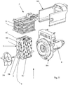
- a motor-pump assembly 1 according to the invention is illustrated.
- Such a motor-pump assembly 1 consists of a pump, just the impeller of which is explicitly depicted, since the other components would not bring anything to clarify the description of the invention, and a single-phase synchronous electric motor 7 with permanent magnets of the inner rotor type.
- the impeller 2A is connected, through a shaft 2B, to the rotor 3 of the single-phase synchronous electric motor 7.
- a plastic overmould 3A is fixedly connected to the rotor 3. Impeller 2A, shaft 2B, rotor 3 and overmould 3A are able to rotate coaxially.
- the rotor 3 is of the type using permanent magnets. It is separated, through an air gap 4, from a stator 5 of the diapason type (sometimes known as forked), which acts as ferromagnetic core.
- a stator 5 is formed from a pack of U-shaped laminations made from ferromagnetic material, stacked in the longitudinal direction (which is the height of the pack of laminations), so that their surfaces stick together.
- the stator 5 is therefore formed from the following portions:
- the length (meaning in the longitudinal direction, i.e. in the direction of the rotation axis of the rotor and transversally to the laminations) of the pole pieces 5C coincides with the length of the stator and with the height of the pack of laminations.
- the length of the rotor 3 is greater than the length of the pole pieces 5C, i.e. the height of the pack of stator laminations 5.
- the rotor has permanent magnets with equal portions, at the longitudinal ends, free from the winding of said pole pieces, i.e. not wrapped around by the pole pieces.
- Aluminium windings 6 are wound around the prongs 5B, so as to totally fill the volume between the prongs 5B and so as to therefore constitute a high-density motor.
- Different embodiments could provide the use of copper windings, in which case the volume occupied by the reels would be less, whilst not having the advantages that can be obtained by aluminium.
- a casing 8 shaped essentially like a tube and formed in one piece with a flange 8B coupled with the volute of the pump (not illustrated since it is conventional), insulates the rotor 3 water-tight with respect to the stator 5, which in turn is housed in a casing 8A coupled with the flange 8B.
- the impeller 2A is connected to the shaft 2B through a known kinematic linkage 11.
- the rotor has a diameter of 19 mm and a length of 45 mm.
- the stator pack has a height of 35 mm, i.e. 22% less than the length of the rotor.
- the height of each of the prongs 5B is therefore about 35 mm.
- the aluminium windings 6 each consist of 510 spirals wound around such prongs 5B, with conductors having a diameter of 0.5 mm. The total weight of such windings is just 62 g.
- a different embodiment could provide reels with 510 copper spirals with conductors having a diameter of 0.40 mm.
- the total weight of such windings would be 126 g.
- the main advantage of the present invention is the particular structural simplicity of the motor-pump assembly, which optimises the spaces using less ferromagnetic material, and therefore a stator having smaller volume, than analogous motors according to the prior art.
- reels are made from copper, they are shorter and use less material than what is normally provided by the prior art.
- the decrease in overall length of the conductors means smaller losses by the joule effect, optimising the thermal yield of the motor-pump assembly.
- reels made from aluminium which is a material with greater resistivity and therefore requires conductors with a larger section than copper does. Since the prongs have a smaller section and the space between the prongs is greater, voluminous aluminium reels can be wound around the stator prongs; the greater heat exchange surface with the outside of aluminium reels allows a more optimised disposal of heat.
- a motor-pump assembly has a motor that works in an area close to saturation of the ferromagnetic material, maximising the electrical and hydraulic efficiency of the motor-pump assembly.
- a motor-pump assembly is advantageously obtained that is lighter than current ones, since there is less lead and lighter reels, above all if made from aluminium.
- a motor according to the invention can be configured like a high-density motor, i.e. such that the space is totally filled with conducting material.
- a motor-pump assembly according to the invention is advantageously less expensive than conventional motor-pump assemblies, and allows the cost of the water discharge function to be minimised, so as to limit the assembly costs of household appliances such as dishwashers and washing machines.
Description
- The object of the present invention is a motor-pump assembly for household appliances such as dishwashers and washing machines, in particular for discharging water, of the type comprising a pump equipped with an impeller and a single-phase synchronous electric motor equipped with a stator and with a rotor mutually separated by a mechanically-formed air gap, the rotor being of the type using permanent magnets, the stator being of the diapason type and equipped with a pack core of laminations and with a pair of pole pieces that wrap coaxially around the rotor.
- It is known that there is a need to make motor-pump discharge assemblies for household appliances, such as washing machines and dishwashers, such as to have the best possible yield, by this meaning the best ratio between the hydraulic operating speed available to the pump (fluid pressure or flow rate) and the electrical power absorbed by the motor associated with the pump, and at the same time having the lowest possible cost of the discharge function.
- This sort of motor-pump assembly normally comprises a pump with an impeller made to rotate by a shaft, and a permanent-magnet single-phase synchronous electric motor, equipped with a stator and a rotor mutually separated by an air gap. The rotor is of the type using permanent magnets and is able to making the shaft connected to the impeller rotate. The stator is of the diapason type and is equipped with a ferromagnetic pack core of U-shaped laminations so as to form two prongs of the diapason; each of these prongs has a copper reel wrapped around it and has a pole piece that, together with the other pole piece, combines to coaxially wrap around the rotor, beyond the air gap. In order to keep noise down and obtain a start-up step that is as fast as possible, a motor-pump assembly according to the invention has a rotor with so-called "slimline" configuration, the ratio between rotor length and diameter being at least equal to 1.3, so as to have a moment of inertia such as to go into resonance with the alternating stator field during the aforementioned start-up step.
- It is known that the distance between the rotor and the stator must be as short as possible, and therefore the volume occupied by the air gap must be as small as possible, to allow the flow to meet the least possible reluctance. For this reason the pole pieces tend to wrap around the rotor: each pole piece takes on a shape with an arc-of-cylinder concave surface that faces the rotor. Moreover, the length of the pole piece, which is the height of the pack of laminations that form such a pole piece, equals the length of the rotor or in any case is substantially not very different from it. In this way, the flux closes as little as possible on the pole pieces, and the condition considered as being optimal is created.
- Since the motor-pump assembly is of the mechanical starting type, there are no electronic start-up control apparatuses. In this way it is more cost-effective to make the motor-pump assembly, but it generally requires special provisions, such as devices with hauling mechanism between the shaft and the impeller. Patents
EP 1308628 andEP 1372245 , to the same Applicant, give some example embodiments of theseUS 4 750 872 is considered as the closest prior art of the subject-matter ofclaim 1 and discloses the features of the preamble of the claim. - Again because the motor-pump assembly is of the mechanical starting type, it is necessary to oversize the reels and the core, since it is necessary to bear the breakaway starting current, which is notoriously of the impulse type. Such a breakaway starting current is not limited by ramps (which are generally obtained by means of control programs loaded onto electronic control circuitry), and therefore it can greatly exceed the current necessary during normal operating conditions. In this way, disadvantageously, large pole pieces and prongs and spirals having a large area need to be used to obtain a magnetic circuit of lower reluctance to bear a high-intensity flux. Indeed, such a large amount of space has to be used that the windings can only be made from copper, since other materials of higher resistivity would require conductors having larger sections and, in order to be wound around the prongs, would need more space than what is actually available in the space between the prongs.
- Patent application
EP 1760859 discloses a motor for a pump in which the core has a shorter axial length than the ends of the pole pieces. In practice, the core can be undersized, with the exception of the pole pieces. This embodiment does not worsen the start-up conditions of the motor, not influencing the breakaway starting current. - Nevertheless, it would be preferable to seek a motor-pump assembly that has greater structural simplicity, possibly using different, more cost-effective materials.
- The technical problem underlying the present invention is that of devising a motor-pump assembly for household appliances with characteristics of particular structural simplicity
- The idea for a solution forming the basis of the present invention is to use a motor with a pack of laminations that is substantially shorter than the rotor.
- In accordance with this idea for a solution, the technical problem is solved by a motor-pump assembly defined in
claim 1. - In a motor-pump assembly according to the invention, the longitudinal ends of the rotor magnets do not have pole pieces on top of them; in this way, there seems to be a pointless waste of material, backed up by the teachings of the prior art, according to which the pole pieces must wrap around the rotor magnets as much as possible, otherwise there will be greater reluctance in the magnetic circuit. However, the inventor has discovered, through experimental tests and numerical simulations, that, even if the height of the pack of laminations decreases (this means that the pole pieces are reduced in the direction of the rotation axis of the rotor) the concatenated flux decreases in a less than proportional way. The flux, indeed, does not only close on the pole pieces, but can also close on other parts of the core, such as the yoke and the prongs.
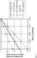
- In
figure 8 it is possible to see the result of a simulation of a pump for the US market, with a rotor having diameter 19 mm and length 45 mm. The X-axis represents the length of the pole pieces (which is the height of the pack of laminations), whereas the Y-axis represents, in non-dimensional values related to one unit, different physical values, including the flux (indicated by small triangles joined by a dotted line) and the height of the stator pack (indicated by small circles joined by a bold line composed of a dash followed by two dots). It can be seen that when the height of the stator pack passes from 40 mm to 32 mm (infigure 8 they are indicated in metres), the flux passes from 1 to slightly over 0.92. In practice, a 20% reduction in height of the pack of laminations surprisingly corresponds to a reduction of about 8.5% of the concatenated flux. - A pump according to the invention therefore has a shorter pack of laminations than an analogous conventional motor, which drives to a core having a smaller section and into reels with spirals of smaller area. Certainly, such a smaller area must be compensated by a greater number of spirals, but this greater number of spirals is proportional to the decrease in flux and not to the reduction in height of the pack of laminations. If, for example, the height of the pack of laminations is reduced by 20%, the area of the spirals is consequently reduced by 20%, whereas the number of spirals only has to increase by 8.5%, resulting in a smaller bulk in the space between the prongs of the stator. The motor can thus be made with a smaller and more compact ferromagnetic core.
- According to a particularly advantageous embodiment, the windings are made from aluminium, which is more cost-effective than copper even if it has higher resistivity. A motor according to the invention can house aluminium coils, which are larger than copper ones. The aluminium windings extend outside requiring greater volume than the equivalent motor with copper windings, but such a greater volume, due to the volume of the windings, is acceptable since it gives a larger heat exchange surface that means more efficient heat disposal.
- Moreover, since it is clear that such a motor-pump assembly has more aluminium and less iron, the motor-pump assembly advantageously weighs less.
- Therefore, a motor-pump assembly according to the invention, in particular comprising a high-density single-phase asynchronous electric motor with aluminium reels, solves the typical problems of household appliance components.
- The characteristics and advantages of the motor-pump assemblies according to the invention shall become clearer from the following description of an example embodiment thereof, given for indicating and not limiting purposes with reference to the attached drawings.
-
-
figure 1 shows a plan view of the motor-pump assembly according to the present invention in which, relative to the pump, just the impeller can be seen; -
figure 2 shows a side view of the motor-pump assembly offigure 1 ; -
figure 3 shows a front view of the motor-pump assembly offigure 1 ; -
figure 4 shows a section view according to the line IV-IV offigure 3 ; -
figure 5 shows an exploded perspective view of the motor-pump assembly offigure 1 ; -
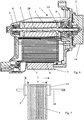
figure 6 shows an enlarged section view according to the line VI-VI offigure 1 -
figure 7 shows a view almost analogous t the view offigure 6 but limited to a few details; - With reference to
figures 1-7 , a motor-pump assembly 1 according to the invention is illustrated. Such a motor-pump assembly 1 consists of a pump, just the impeller of which is explicitly depicted, since the other components would not bring anything to clarify the description of the invention, and a single-phase synchronouselectric motor 7 with permanent magnets of the inner rotor type. - The
impeller 2A is connected, through ashaft 2B, to therotor 3 of the single-phase synchronouselectric motor 7. Aplastic overmould 3A is fixedly connected to therotor 3.Impeller 2A,shaft 2B,rotor 3 andovermould 3A are able to rotate coaxially. -
Bearings shaft 2B and, consequently, therotor 3, in such a way that they can rotate. - The
rotor 3 is of the type using permanent magnets. It is separated, through anair gap 4, from astator 5 of the diapason type (sometimes known as forked), which acts as ferromagnetic core. Such astator 5 is formed from a pack of U-shaped laminations made from ferromagnetic material, stacked in the longitudinal direction (which is the height of the pack of laminations), so that their surfaces stick together. Thestator 5 is therefore formed from the following portions: - two
prongs 5B, surrounded by windings (described hereafter); - two
pole pieces 5C, with an arc of cylinder-shaped concave inner surface that faces therotor 3; - a yoke 5A.
- The length (meaning in the longitudinal direction, i.e. in the direction of the rotation axis of the rotor and transversally to the laminations) of the
pole pieces 5C coincides with the length of the stator and with the height of the pack of laminations. - The length of the
rotor 3 is greater than the length of thepole pieces 5C, i.e. the height of the pack ofstator laminations 5. The rotor has permanent magnets with equal portions, at the longitudinal ends, free from the winding of said pole pieces, i.e. not wrapped around by the pole pieces. -
Aluminium windings 6 are wound around theprongs 5B, so as to totally fill the volume between theprongs 5B and so as to therefore constitute a high-density motor. Different embodiments could provide the use of copper windings, in which case the volume occupied by the reels would be less, whilst not having the advantages that can be obtained by aluminium. - A
casing 8, shaped essentially like a tube and formed in one piece with a flange 8B coupled with the volute of the pump (not illustrated since it is conventional), insulates therotor 3 water-tight with respect to thestator 5, which in turn is housed in acasing 8A coupled with the flange 8B. - The
impeller 2A is connected to theshaft 2B through a knownkinematic linkage 11. - In the example shown, the rotor has a diameter of 19 mm and a length of 45 mm. The stator pack has a height of 35 mm, i.e. 22% less than the length of the rotor. The height of each of the
prongs 5B is therefore about 35 mm. Thealuminium windings 6 each consist of 510 spirals wound aroundsuch prongs 5B, with conductors having a diameter of 0.5 mm. The total weight of such windings is just 62 g. - A different embodiment could provide reels with 510 copper spirals with conductors having a diameter of 0.40 mm. The total weight of such windings would be 126 g.
- According to the prior art, with a rotor having a diameter of 19 mm and a length of 45 mm, copper windings with 470 spirals having a diameter of 0.40 mm would be required, for a weight of 165 g.
- The pack of laminations that constitutes the
stator 5 has a height s that is substantially less than the length r of the rotor 3 (according to the prior art, it would be r = s or else r ≈ s). Infigure 8 this concept is expressed with exaggerated dimensions. - The main advantage of the present invention is the particular structural simplicity of the motor-pump assembly, which optimises the spaces using less ferromagnetic material, and therefore a stator having smaller volume, than analogous motors according to the prior art.
- Moreover, in embodiments in which the reels are made from copper, they are shorter and use less material than what is normally provided by the prior art. The decrease in overall length of the conductors means smaller losses by the joule effect, optimising the thermal yield of the motor-pump assembly.
- Alternatively, it is advantageously possible to use reels made from aluminium, which is a material with greater resistivity and therefore requires conductors with a larger section than copper does. Since the prongs have a smaller section and the space between the prongs is greater, voluminous aluminium reels can be wound around the stator prongs; the greater heat exchange surface with the outside of aluminium reels allows a more optimised disposal of heat.
- Advantageously, a motor-pump assembly according to the invention has a motor that works in an area close to saturation of the ferromagnetic material, maximising the electrical and hydraulic efficiency of the motor-pump assembly.
- Moreover, as has been seen with the numerical examples, a motor-pump assembly is advantageously obtained that is lighter than current ones, since there is less lead and lighter reels, above all if made from aluminium.
- A motor according to the invention can be configured like a high-density motor, i.e. such that the space is totally filled with conducting material.
- It is clear that a motor-pump assembly according to the invention is advantageously less expensive than conventional motor-pump assemblies, and allows the cost of the water discharge function to be minimised, so as to limit the assembly costs of household appliances such as dishwashers and washing machines.
Claims (10)
- Motor-pump assembly for household appliances (1) such as dishwashers and washing machines, in particular for discharging water, comprising a pump equipped with an impeller (2A) and an electric motor (7) with mechanical start-up equipped with a stator (5) and with a rotor (3) mutually separated by an air gap (4), said rotor (3) being of the type using permanent magnets, said stator (5) being of the diapason type and equipped with a pack core of laminations and with a pair of pole pieces (5C) that wrap coaxially around said rotor (3), characterised in that the electric motor (7) is a single-phase electric motor and in that the length (s) of said pole pieces (5C) of the stator (5) is at least 15% less than the length (r) of the permanent magnet of said rotor (3).
- Motor-pump assembly for household appliances according to any one of the previous claims, characterised in that the length (s) of said pole pieces (5C) of the stator (5) is between 20% and 35% less than the length (r) of the permanent magnet of said rotor (3),
- Motor-pump assembly for household appliances according to claim 1 or 2, characterised in that reels (6) of aluminium wire are wound around said stator (5).
- Motor-pump assembly for household appliances according to any one of the previous claims 1-3, characterised in that the laminations of said stator (5) are substantially U-shaped, the arms of which, in the extreme position, define said pole pieces (5C).
- Motor-pump assembly for household appliances according to any one of the previous claims, characterised in that the length of said pole pieces (5C) is equal to the height (s) of the pack of laminations of said stator (5).
- Motor-pump assembly for household appliances according to any one of the previous claims, characterised in that said reels (6) occupy the entire space between said prongs (5B) so as to make a high-density motor.
- Motor-pump assembly for household appliances according to any one of the previous claims, characterised in that the length (r) of the permanent magnet of said rotor (3) is 45 mm, the diameter of said rotor (3) is 19 mm, and the length (s) of said pole pieces (5C) is 35 mm within the usual tolerance margins.
- Motor-pump assembly for household appliances according to claim 7, characterised in that it has 510 aluminium spirals with wire having a diameter of 0.5 mm, within a tolerance margin of 10%.
- Motor-pump assembly for household appliances according to claim 7, characterised in that it has 510 copper spirals with wire having a diameter of 0.45 mm, within a tolerance margin of 10%.
- Motor-pump assembly for household appliances according to any one of the previous claims, characterised in that said motor has a rotor using permanent magnets with equal portions, at the longitudinal ends, free from the winding of said pole pieces.
Priority Applications (4)
| Application Number | Priority Date | Filing Date | Title |
|---|---|---|---|
| EP07425519.1A EP2025944B1 (en) | 2007-08-09 | 2007-08-09 | Mono-phase syncronous electric motorfor household appliances |
| US12/181,885 US20090039723A1 (en) | 2007-08-09 | 2008-07-29 | Motor-Pump Assembly for Household Appliances |
| KR1020080078176A KR101460805B1 (en) | 2007-08-09 | 2008-08-08 | Motor-pump assembly for household appliances |
| CN2008101473543A CN101409469B (en) | 2007-08-09 | 2008-08-11 | Motor-pump assembly for household appliances |
Applications Claiming Priority (1)
| Application Number | Priority Date | Filing Date | Title |
|---|---|---|---|
| EP07425519.1A EP2025944B1 (en) | 2007-08-09 | 2007-08-09 | Mono-phase syncronous electric motorfor household appliances |
Publications (2)
| Publication Number | Publication Date |
|---|---|
| EP2025944A1 EP2025944A1 (en) | 2009-02-18 |
| EP2025944B1 true EP2025944B1 (en) | 2017-08-09 |
Family
ID=38996693
Family Applications (1)
| Application Number | Title | Priority Date | Filing Date |
|---|---|---|---|
| EP07425519.1A Revoked EP2025944B1 (en) | 2007-08-09 | 2007-08-09 | Mono-phase syncronous electric motorfor household appliances |
Country Status (4)
| Country | Link |
|---|---|
| US (1) | US20090039723A1 (en) |
| EP (1) | EP2025944B1 (en) |
| KR (1) | KR101460805B1 (en) |
| CN (1) | CN101409469B (en) |
Families Citing this family (5)
| Publication number | Priority date | Publication date | Assignee | Title |
|---|---|---|---|---|
| CN102242717B (en) * | 2010-05-14 | 2013-09-25 | 于佳衣 | Integral and liquid-lubrication electric water pump driven by permanent magnet brushless direct current motor |
| JP2012059592A (en) * | 2010-09-10 | 2012-03-22 | Toyota Motor Corp | Fuel cell system, motor, air compressor, pump, and method for designing motor |
| US20140261560A1 (en) * | 2013-03-13 | 2014-09-18 | Whirlpool Corporation | Dishwasher with variable flow rate valve |
| CN105322730B (en) * | 2014-07-28 | 2017-09-15 | 江门市地尔汉宇电器股份有限公司 | A kind of permagnetic synchronous motor and preparation method thereof |
| CN107240971B (en) * | 2016-03-28 | 2020-10-16 | 德昌电机(深圳)有限公司 | Motor and stator thereof |
Citations (48)
| Publication number | Priority date | Publication date | Assignee | Title |
|---|---|---|---|---|
| US3848146A (en) | 1972-03-31 | 1974-11-12 | Rca Corp | Ac motor |
| DE2421367A1 (en) | 1974-05-03 | 1975-11-06 | Vdo Schindling | ELECTRIC CLOCK |
| US3963949A (en) | 1972-10-26 | 1976-06-15 | General Electric Company | Laminated structure with insulating member formed in situ thereon |
| GB1461208A (en) | 1974-04-05 | 1977-01-13 | Philips Electronic Associated | Apparatus comprising a synchronous motor |
| US4008985A (en) | 1974-02-14 | 1977-02-22 | U.S. Philips Corporation | Pumping device for fluids |
| DE2318728B2 (en) | 1973-04-13 | 1977-04-28 | Dual Gebrüder Steidinger, 7742 St Georgen | SYNCHRONOUS MOTOR WITH STARTING DEVICE |
| DE2559635A1 (en) | 1975-01-27 | 1977-04-28 | Vdo Schindling | Step-by-step monophase motor - has magneto-electric motor with two or more poles and L-shaped stator |
| BE874609A (en) | 1978-03-08 | 1979-07-02 | Baensch Tetra Werke | SINGLE-PHASE SYNCHRONOUS ELECTRIC MOTOR |
| DE2809974A1 (en) | 1978-03-08 | 1979-11-08 | Baensch Tetra Werke | Aquarium water circulation single phase sync. motor - has twin-pole stator with angle between poles of 120 degrees or three pole stator with regularly spaced poles |
| EP0015956B1 (en) | 1978-04-14 | 1982-07-28 | Les Fils De F. Romanet S.A.R.L. | Device for driving a toothed wheel by a step-by-step motor |
| DE3518697A1 (en) | 1985-05-24 | 1986-11-27 | Philips Patentverwaltung Gmbh, 2000 Hamburg | Single-phase synchronous motor having a two-pole, permanent-magnet energised rotor (hybrid motor I) |
| DE2857221C2 (en) | 1977-09-07 | 1988-02-04 | Kabushiki Kaisha Suwa Seikosha, Tokio/Tokyo, Jp | |
| US4750872A (en) | 1985-07-01 | 1988-06-14 | Easthorpe Investments Ltd. | Centrifugal pump with damped motor connection |
| DE8807108U1 (en) | 1988-05-31 | 1989-03-30 | Siemens Ag, 1000 Berlin Und 8000 Muenchen, De | |
| CN2041735U (en) | 1988-06-23 | 1989-07-26 | 苏荣森 | Synchronous electric fan with gentle breeze |
| DE3810158A1 (en) | 1988-03-25 | 1989-10-12 | Bosch Gmbh Robert | Single-phase synchronous motor |
| DE3810159A1 (en) | 1988-03-25 | 1989-10-19 | Bosch Gmbh Robert | Single-phase synchronous motor |
| DE3818532A1 (en) | 1988-05-31 | 1989-12-07 | Siemens Ag | Single-phase synchronous motor |
| DE3918333A1 (en) | 1988-06-13 | 1989-12-14 | Copreci S Coop Ltda | IMPROVEMENTS OF ELECTRIC PUMPS USED IN ELECTRIC HOUSEHOLD APPLIANCES |
| EP0581598A1 (en) | 1992-07-31 | 1994-02-02 | Mabuchi Motor Kabushiki Kaisha | Synchronous motor |
| EP0487785B1 (en) | 1990-11-30 | 1994-05-25 | Siemens Aktiengesellschaft | Connection for a pump impeller |
| EP0601220B1 (en) | 1992-11-30 | 1995-06-21 | Siemens Aktiengesellschaft | Hydraulic pump system, in particular liquid drain pump |
| DE19518215A1 (en) | 1994-05-10 | 1995-11-16 | Rena France | Hydro-pump motor |
| DE4424257A1 (en) | 1994-07-09 | 1996-01-18 | Aweco Kunststofftech Geraete | High-power centrifugal pump with single-phase sync. motor drive for dish washing machines |
| DE4424996A1 (en) | 1994-07-15 | 1996-01-18 | Oase Pumpen | Centrifugal pump, especially for fountains |
| EP0569306B1 (en) | 1992-05-05 | 1996-03-20 | Rena France (S.A.) | Improvements to an electric motor and hydraulic pump using this motor |
| DE69114678T2 (en) | 1990-07-16 | 1996-07-04 | Johnson Electric Sa | ELECTRIC MOTOR. |
| US5668425A (en) | 1995-01-19 | 1997-09-16 | Askoll A.P.A. | Startup device for the rotor of a permanent-magnet synchronous motor |
| US5708406A (en) | 1995-03-20 | 1998-01-13 | Asmo Co. Ltd. | Rotary actuator |
| CN1184208A (en) | 1997-12-01 | 1998-06-10 | 王莹 | Electromagnetic pumping unit |
| US6008554A (en) | 1995-12-21 | 1999-12-28 | U.S. Philips Corporation | Claw-pole stepper motor having a rotor supported by an axial bearing and a rotor-magnet extending beyond an end of a stator return element |
| DE19907556A1 (en) | 1998-09-02 | 2000-03-09 | Bsh Bosch Siemens Hausgeraete | Washing solution pump for domestic appliances is driven by single-phase motor with permanently magnetic rotor |
| US6469408B2 (en) | 2000-07-31 | 2002-10-22 | Mitsubishi Denki Kabushiki Kaisha | Alternator |
| US6478555B1 (en) | 1999-06-16 | 2002-11-12 | Lg Electronics, Inc. | Apparatus for controlling noise and vibration for drain pump |
| CN1097335C (en) | 1996-05-29 | 2002-12-25 | Abb股份公司 | Hydroelectric power generating equipment |
| US20030034697A1 (en) | 2001-05-07 | 2003-02-20 | Goldner Ronald B. | Electromagnetic linear generator and shock absorber |
| EP1308628A1 (en) | 2001-10-30 | 2003-05-07 | Askoll Holding S.r.l. | Coupling device |
| EP0983630B1 (en) | 1998-03-19 | 2003-10-15 | Askoll Holding S.r.l. | Device for transmitting motion between the rotor of a synchronous permanent-magnet motor and a working part, said device having an increased free rotation angle |
| US6707216B2 (en) | 2001-06-14 | 2004-03-16 | Lg Electronics Inc. | Single phase line start permanent magnet synchronous motor |
| DE60102011T2 (en) | 2000-04-27 | 2004-09-16 | Askoll Holding S.R.L., Dueville | Electric motor with permanent magnets for circulating pumps of heating systems |
| GB2407712A (en) | 2003-10-29 | 2005-05-04 | Smith Corp A O | Stator core construction for an electric machine |
| KR20050044445A (en) | 2001-11-15 | 2005-05-12 | 아르끄마 | Method for working or forming metals in the presence of aqueous lubricants based on methanesulphonic acid |
| DE10247094B4 (en) | 2002-10-09 | 2005-06-02 | Siemens Ag | clockwork |
| DE102005008965A1 (en) | 2005-02-28 | 2006-09-07 | Tunze Aquarientechnik Gmbh | Synchronous motor, in particular for an aquarium pump |
| WO2006108105A2 (en) | 2005-04-06 | 2006-10-12 | Inoki, Kanji | Electrical machine with segmented claw poles |
| EP1760861A1 (en) | 2005-08-30 | 2007-03-07 | Askoll Holding S.r.l. | Permanent-magnet two-phase synchronous electric motor with mechanical start-up for washing machines and similar household appliances, in particular for washing pumps |
| EP1760859A1 (en) | 2005-08-30 | 2007-03-07 | Askoll Holding S.r.l. | Permanent-magnet mono-phase synchronous electric motor with improved stator structure, in particular for discharge pumps of washing machines and similar household appliances |
| US7638913B2 (en) | 2005-05-27 | 2009-12-29 | A.O. Smith Corporation | Rotor core with spacers |
Family Cites Families (1)
| Publication number | Priority date | Publication date | Assignee | Title |
|---|---|---|---|---|
| KR100421394B1 (en) | 2002-02-22 | 2004-03-09 | 엘지전자 주식회사 | Single capacitor synchronous motor |
-
2007
- 2007-08-09 EP EP07425519.1A patent/EP2025944B1/en not_active Revoked
-
2008
- 2008-07-29 US US12/181,885 patent/US20090039723A1/en not_active Abandoned
- 2008-08-08 KR KR1020080078176A patent/KR101460805B1/en active IP Right Grant
- 2008-08-11 CN CN2008101473543A patent/CN101409469B/en active Active
Patent Citations (49)
| Publication number | Priority date | Publication date | Assignee | Title |
|---|---|---|---|---|
| US3848146A (en) | 1972-03-31 | 1974-11-12 | Rca Corp | Ac motor |
| US3963949A (en) | 1972-10-26 | 1976-06-15 | General Electric Company | Laminated structure with insulating member formed in situ thereon |
| DE2318728B2 (en) | 1973-04-13 | 1977-04-28 | Dual Gebrüder Steidinger, 7742 St Georgen | SYNCHRONOUS MOTOR WITH STARTING DEVICE |
| US4008985A (en) | 1974-02-14 | 1977-02-22 | U.S. Philips Corporation | Pumping device for fluids |
| GB1461208A (en) | 1974-04-05 | 1977-01-13 | Philips Electronic Associated | Apparatus comprising a synchronous motor |
| DE2421367A1 (en) | 1974-05-03 | 1975-11-06 | Vdo Schindling | ELECTRIC CLOCK |
| DE2559635A1 (en) | 1975-01-27 | 1977-04-28 | Vdo Schindling | Step-by-step monophase motor - has magneto-electric motor with two or more poles and L-shaped stator |
| DE2857221C2 (en) | 1977-09-07 | 1988-02-04 | Kabushiki Kaisha Suwa Seikosha, Tokio/Tokyo, Jp | |
| BE874609A (en) | 1978-03-08 | 1979-07-02 | Baensch Tetra Werke | SINGLE-PHASE SYNCHRONOUS ELECTRIC MOTOR |
| DE2809974A1 (en) | 1978-03-08 | 1979-11-08 | Baensch Tetra Werke | Aquarium water circulation single phase sync. motor - has twin-pole stator with angle between poles of 120 degrees or three pole stator with regularly spaced poles |
| EP0015956B1 (en) | 1978-04-14 | 1982-07-28 | Les Fils De F. Romanet S.A.R.L. | Device for driving a toothed wheel by a step-by-step motor |
| DE3518697A1 (en) | 1985-05-24 | 1986-11-27 | Philips Patentverwaltung Gmbh, 2000 Hamburg | Single-phase synchronous motor having a two-pole, permanent-magnet energised rotor (hybrid motor I) |
| US4750872A (en) | 1985-07-01 | 1988-06-14 | Easthorpe Investments Ltd. | Centrifugal pump with damped motor connection |
| DE3810158A1 (en) | 1988-03-25 | 1989-10-12 | Bosch Gmbh Robert | Single-phase synchronous motor |
| DE3810159A1 (en) | 1988-03-25 | 1989-10-19 | Bosch Gmbh Robert | Single-phase synchronous motor |
| DE3818532A1 (en) | 1988-05-31 | 1989-12-07 | Siemens Ag | Single-phase synchronous motor |
| DE8807108U1 (en) | 1988-05-31 | 1989-03-30 | Siemens Ag, 1000 Berlin Und 8000 Muenchen, De | |
| DE3918333A1 (en) | 1988-06-13 | 1989-12-14 | Copreci S Coop Ltda | IMPROVEMENTS OF ELECTRIC PUMPS USED IN ELECTRIC HOUSEHOLD APPLIANCES |
| CN2041735U (en) | 1988-06-23 | 1989-07-26 | 苏荣森 | Synchronous electric fan with gentle breeze |
| DE69114678T2 (en) | 1990-07-16 | 1996-07-04 | Johnson Electric Sa | ELECTRIC MOTOR. |
| EP0487785B1 (en) | 1990-11-30 | 1994-05-25 | Siemens Aktiengesellschaft | Connection for a pump impeller |
| EP0569306B1 (en) | 1992-05-05 | 1996-03-20 | Rena France (S.A.) | Improvements to an electric motor and hydraulic pump using this motor |
| EP0581598A1 (en) | 1992-07-31 | 1994-02-02 | Mabuchi Motor Kabushiki Kaisha | Synchronous motor |
| EP0601220B1 (en) | 1992-11-30 | 1995-06-21 | Siemens Aktiengesellschaft | Hydraulic pump system, in particular liquid drain pump |
| DE19518215A1 (en) | 1994-05-10 | 1995-11-16 | Rena France | Hydro-pump motor |
| DE4424257A1 (en) | 1994-07-09 | 1996-01-18 | Aweco Kunststofftech Geraete | High-power centrifugal pump with single-phase sync. motor drive for dish washing machines |
| DE4424996A1 (en) | 1994-07-15 | 1996-01-18 | Oase Pumpen | Centrifugal pump, especially for fountains |
| US5668425A (en) | 1995-01-19 | 1997-09-16 | Askoll A.P.A. | Startup device for the rotor of a permanent-magnet synchronous motor |
| US5708406A (en) | 1995-03-20 | 1998-01-13 | Asmo Co. Ltd. | Rotary actuator |
| US6008554A (en) | 1995-12-21 | 1999-12-28 | U.S. Philips Corporation | Claw-pole stepper motor having a rotor supported by an axial bearing and a rotor-magnet extending beyond an end of a stator return element |
| CN1097335C (en) | 1996-05-29 | 2002-12-25 | Abb股份公司 | Hydroelectric power generating equipment |
| CN1184208A (en) | 1997-12-01 | 1998-06-10 | 王莹 | Electromagnetic pumping unit |
| EP0983630B1 (en) | 1998-03-19 | 2003-10-15 | Askoll Holding S.r.l. | Device for transmitting motion between the rotor of a synchronous permanent-magnet motor and a working part, said device having an increased free rotation angle |
| EP1372245A1 (en) | 1998-03-19 | 2003-12-17 | Askoll Holding S.r.l. | Device for transmitting motion between the rotor of a synchronous permanent-magnet motor and the working part, said device having an increased free rotation angle |
| DE19907556A1 (en) | 1998-09-02 | 2000-03-09 | Bsh Bosch Siemens Hausgeraete | Washing solution pump for domestic appliances is driven by single-phase motor with permanently magnetic rotor |
| US6478555B1 (en) | 1999-06-16 | 2002-11-12 | Lg Electronics, Inc. | Apparatus for controlling noise and vibration for drain pump |
| DE60102011T2 (en) | 2000-04-27 | 2004-09-16 | Askoll Holding S.R.L., Dueville | Electric motor with permanent magnets for circulating pumps of heating systems |
| US6469408B2 (en) | 2000-07-31 | 2002-10-22 | Mitsubishi Denki Kabushiki Kaisha | Alternator |
| US20030034697A1 (en) | 2001-05-07 | 2003-02-20 | Goldner Ronald B. | Electromagnetic linear generator and shock absorber |
| US6707216B2 (en) | 2001-06-14 | 2004-03-16 | Lg Electronics Inc. | Single phase line start permanent magnet synchronous motor |
| EP1308628A1 (en) | 2001-10-30 | 2003-05-07 | Askoll Holding S.r.l. | Coupling device |
| KR20050044445A (en) | 2001-11-15 | 2005-05-12 | 아르끄마 | Method for working or forming metals in the presence of aqueous lubricants based on methanesulphonic acid |
| DE10247094B4 (en) | 2002-10-09 | 2005-06-02 | Siemens Ag | clockwork |
| GB2407712A (en) | 2003-10-29 | 2005-05-04 | Smith Corp A O | Stator core construction for an electric machine |
| DE102005008965A1 (en) | 2005-02-28 | 2006-09-07 | Tunze Aquarientechnik Gmbh | Synchronous motor, in particular for an aquarium pump |
| WO2006108105A2 (en) | 2005-04-06 | 2006-10-12 | Inoki, Kanji | Electrical machine with segmented claw poles |
| US7638913B2 (en) | 2005-05-27 | 2009-12-29 | A.O. Smith Corporation | Rotor core with spacers |
| EP1760861A1 (en) | 2005-08-30 | 2007-03-07 | Askoll Holding S.r.l. | Permanent-magnet two-phase synchronous electric motor with mechanical start-up for washing machines and similar household appliances, in particular for washing pumps |
| EP1760859A1 (en) | 2005-08-30 | 2007-03-07 | Askoll Holding S.r.l. | Permanent-magnet mono-phase synchronous electric motor with improved stator structure, in particular for discharge pumps of washing machines and similar household appliances |
Non-Patent Citations (6)
| Title |
|---|
| BEGLAUBIGTE ABSCHRIFT DER NIEDERSCHRIFT DES NOTARS DR. PATRICK MAASS |
| EIDESSTATTLICHE VERSICHERUNG VON HERRN CHRISTOPH HEMMEKE |
| KUNDENZEICHNUNG ZUR ENTLEERUNGSPUMPE DPS 25-041 |
| MONTAGEZEICHNUNG FÜR DIE ENTLEERUNGSPUMPE DPS 25-041 |
| SCHEMMANN, H.: "Theoretische und experimentelle Untersuchungen über das dynamische Verhalten eines Einphasen-Synchronmotors mit dau- ermagnetischem Läufer.", 1971, Technische Hochschule Eindhoven, XP055488374 |
| WÄHNER, L: "Entwicklung eines Pumpenantriebs mit einem einsträngigen Synchronmotor (Dissertation)", 2001, pages 1 - 92, XP055488362 |
Also Published As
| Publication number | Publication date |
|---|---|
| US20090039723A1 (en) | 2009-02-12 |
| CN101409469B (en) | 2013-12-04 |
| KR20090015872A (en) | 2009-02-12 |
| EP2025944A1 (en) | 2009-02-18 |
| CN101409469A (en) | 2009-04-15 |
| KR101460805B1 (en) | 2014-11-11 |
Similar Documents
| Publication | Publication Date | Title |
|---|---|---|
| EP2025944B1 (en) | Mono-phase syncronous electric motorfor household appliances | |
| EP1760859B1 (en) | Permanent-magnet mono-phase synchronous electric motor with improved stator structure, in particular for discharge pumps of washing machines and similar household appliances | |
| JP4092128B2 (en) | Electric machine having at least one magnetic field detector | |
| JP5470015B2 (en) | Rotating electric machine | |
| US4983866A (en) | Encapsulated armature for electric motor | |
| EP2006976B1 (en) | Two-phase synchronous electric motor | |
| CN102810964A (en) | Switched reluctance motor | |
| AU725905B2 (en) | Permanent magnetic dynamo | |
| CA2769128C (en) | Electrical machine, in particular an electrical generator | |
| KR101916265B1 (en) | Slim Type Stator, Sensorless Type Single Phase Motor and Cooling Fan Using the Same | |
| CN101657955B (en) | Electric machine | |
| US7755245B2 (en) | Synchronous motor with permanent-magnet rotor | |
| EP1760861B1 (en) | Permanent-magnet two-phase synchronous electric motor with mechanical start-up for washing machines and similar household appliances, in particular for washing pumps | |
| US20230296099A1 (en) | Integrated pump assembly with one moving part with stacked stator | |
| CN113169682A (en) | Electric machine | |
| EP1885041A2 (en) | Distributed coils stator for external rotor three phase electric motors | |
| EP2006059A2 (en) | Power planer | |
| EP2132857A2 (en) | Axial flux electrical machines | |
| US20220186736A1 (en) | Integrated pump assembly with one moving part | |
| CN216290401U (en) | Embedded winding-free iron core brushless motor | |
| GB2193045A (en) | An armature for an electric motor | |
| JP2020068562A (en) | Dynamo-electric motor, electric blower using the same, and vacuum cleaner | |
| JP5586275B2 (en) | motor | |
| Hanitsch et al. | Small Brushless Dc-Motor With Sensorless Control-A Hollow Shaft Prototype | |
| CA2596107A1 (en) | Distributed coil stator for external rotor three phase electric motors |
Legal Events
| Date | Code | Title | Description |
|---|---|---|---|
| PUAI | Public reference made under article 153(3) epc to a published international application that has entered the european phase |
Free format text: ORIGINAL CODE: 0009012 |
|
| AK | Designated contracting states |
Kind code of ref document: A1 Designated state(s): AT BE BG CH CY CZ DE DK EE ES FI FR GB GR HU IE IS IT LI LT LU LV MC MT NL PL PT RO SE SI SK TR |
|
| AX | Request for extension of the european patent |
Extension state: AL BA HR MK RS |
|
| 17P | Request for examination filed |
Effective date: 20090812 |
|
| 17Q | First examination report despatched |
Effective date: 20090914 |
|
| AKX | Designation fees paid |
Designated state(s): AT BE BG CH CY CZ DE DK EE ES FI FR GB GR HU IE IS IT LI LT LU LV MC MT NL PL PT RO SE SI SK TR |
|
| TPAC | Observations filed by third parties |
Free format text: ORIGINAL CODE: EPIDOSNTIPA |
|
| STAA | Information on the status of an ep patent application or granted ep patent |
Free format text: STATUS: EXAMINATION IS IN PROGRESS |
|
| GRAP | Despatch of communication of intention to grant a patent |
Free format text: ORIGINAL CODE: EPIDOSNIGR1 |
|
| STAA | Information on the status of an ep patent application or granted ep patent |
Free format text: STATUS: GRANT OF PATENT IS INTENDED |
|
| INTG | Intention to grant announced |
Effective date: 20170316 |
|
| GRAS | Grant fee paid |
Free format text: ORIGINAL CODE: EPIDOSNIGR3 |
|
| GRAA | (expected) grant |
Free format text: ORIGINAL CODE: 0009210 |
|
| STAA | Information on the status of an ep patent application or granted ep patent |
Free format text: STATUS: THE PATENT HAS BEEN GRANTED |
|
| AK | Designated contracting states |
Kind code of ref document: B1 Designated state(s): AT BE BG CH CY CZ DE DK EE ES FI FR GB GR HU IE IS IT LI LT LU LV MC MT NL PL PT RO SE SI SK TR |
|
| REG | Reference to a national code |
Ref country code: GB Ref legal event code: FG4D |
|
| REG | Reference to a national code |
Ref country code: CH Ref legal event code: EP Ref country code: AT Ref legal event code: REF Ref document number: 917176 Country of ref document: AT Kind code of ref document: T Effective date: 20170815 |
|
| REG | Reference to a national code |
Ref country code: IE Ref legal event code: FG4D |
|
| REG | Reference to a national code |
Ref country code: DE Ref legal event code: R096 Ref document number: 602007051907 Country of ref document: DE |
|
| REG | Reference to a national code |
Ref country code: RO Ref legal event code: EPE |
|
| REG | Reference to a national code |
Ref country code: NL Ref legal event code: MP Effective date: 20170809 |
|
| REG | Reference to a national code |
Ref country code: LT Ref legal event code: MG4D |
|
| REG | Reference to a national code |
Ref country code: AT Ref legal event code: MK05 Ref document number: 917176 Country of ref document: AT Kind code of ref document: T Effective date: 20170809 |
|
| PG25 | Lapsed in a contracting state [announced via postgrant information from national office to epo] |
Ref country code: LT Free format text: LAPSE BECAUSE OF FAILURE TO SUBMIT A TRANSLATION OF THE DESCRIPTION OR TO PAY THE FEE WITHIN THE PRESCRIBED TIME-LIMIT Effective date: 20170809 Ref country code: SE Free format text: LAPSE BECAUSE OF FAILURE TO SUBMIT A TRANSLATION OF THE DESCRIPTION OR TO PAY THE FEE WITHIN THE PRESCRIBED TIME-LIMIT Effective date: 20170809 Ref country code: NL Free format text: LAPSE BECAUSE OF FAILURE TO SUBMIT A TRANSLATION OF THE DESCRIPTION OR TO PAY THE FEE WITHIN THE PRESCRIBED TIME-LIMIT Effective date: 20170809 Ref country code: AT Free format text: LAPSE BECAUSE OF FAILURE TO SUBMIT A TRANSLATION OF THE DESCRIPTION OR TO PAY THE FEE WITHIN THE PRESCRIBED TIME-LIMIT Effective date: 20170809 Ref country code: FI Free format text: LAPSE BECAUSE OF FAILURE TO SUBMIT A TRANSLATION OF THE DESCRIPTION OR TO PAY THE FEE WITHIN THE PRESCRIBED TIME-LIMIT Effective date: 20170809 |
|
| PG25 | Lapsed in a contracting state [announced via postgrant information from national office to epo] |
Ref country code: BG Free format text: LAPSE BECAUSE OF FAILURE TO SUBMIT A TRANSLATION OF THE DESCRIPTION OR TO PAY THE FEE WITHIN THE PRESCRIBED TIME-LIMIT Effective date: 20171109 Ref country code: ES Free format text: LAPSE BECAUSE OF FAILURE TO SUBMIT A TRANSLATION OF THE DESCRIPTION OR TO PAY THE FEE WITHIN THE PRESCRIBED TIME-LIMIT Effective date: 20170809 Ref country code: IS Free format text: LAPSE BECAUSE OF FAILURE TO SUBMIT A TRANSLATION OF THE DESCRIPTION OR TO PAY THE FEE WITHIN THE PRESCRIBED TIME-LIMIT Effective date: 20171209 Ref country code: LV Free format text: LAPSE BECAUSE OF FAILURE TO SUBMIT A TRANSLATION OF THE DESCRIPTION OR TO PAY THE FEE WITHIN THE PRESCRIBED TIME-LIMIT Effective date: 20170809 Ref country code: GR Free format text: LAPSE BECAUSE OF FAILURE TO SUBMIT A TRANSLATION OF THE DESCRIPTION OR TO PAY THE FEE WITHIN THE PRESCRIBED TIME-LIMIT Effective date: 20171110 Ref country code: PL Free format text: LAPSE BECAUSE OF FAILURE TO SUBMIT A TRANSLATION OF THE DESCRIPTION OR TO PAY THE FEE WITHIN THE PRESCRIBED TIME-LIMIT Effective date: 20170809 |
|
| REG | Reference to a national code |
Ref country code: CH Ref legal event code: PL |
|
| REG | Reference to a national code |
Ref country code: SK Ref legal event code: T3 Ref document number: E 26027 Country of ref document: SK |
|
| PG25 | Lapsed in a contracting state [announced via postgrant information from national office to epo] |
Ref country code: CZ Free format text: LAPSE BECAUSE OF FAILURE TO SUBMIT A TRANSLATION OF THE DESCRIPTION OR TO PAY THE FEE WITHIN THE PRESCRIBED TIME-LIMIT Effective date: 20170809 Ref country code: DK Free format text: LAPSE BECAUSE OF FAILURE TO SUBMIT A TRANSLATION OF THE DESCRIPTION OR TO PAY THE FEE WITHIN THE PRESCRIBED TIME-LIMIT Effective date: 20170809 Ref country code: LI Free format text: LAPSE BECAUSE OF NON-PAYMENT OF DUE FEES Effective date: 20170831 Ref country code: CH Free format text: LAPSE BECAUSE OF NON-PAYMENT OF DUE FEES Effective date: 20170831 |
|
| REG | Reference to a national code |
Ref country code: DE Ref legal event code: R026 Ref document number: 602007051907 Country of ref document: DE |
|
| PLBI | Opposition filed |
Free format text: ORIGINAL CODE: 0009260 |
|
| REG | Reference to a national code |
Ref country code: IE Ref legal event code: MM4A |
|
| PG25 | Lapsed in a contracting state [announced via postgrant information from national office to epo] |
Ref country code: EE Free format text: LAPSE BECAUSE OF FAILURE TO SUBMIT A TRANSLATION OF THE DESCRIPTION OR TO PAY THE FEE WITHIN THE PRESCRIBED TIME-LIMIT Effective date: 20170809 Ref country code: MC Free format text: LAPSE BECAUSE OF FAILURE TO SUBMIT A TRANSLATION OF THE DESCRIPTION OR TO PAY THE FEE WITHIN THE PRESCRIBED TIME-LIMIT Effective date: 20170809 |
|
| REG | Reference to a national code |
Ref country code: BE Ref legal event code: MM Effective date: 20170831 |
|
| 26 | Opposition filed |
Opponent name: HANNING ELEKTRO-WERKE GMBH & CO. KG Effective date: 20180507 |
|
| PLAX | Notice of opposition and request to file observation + time limit sent |
Free format text: ORIGINAL CODE: EPIDOSNOBS2 |
|
| PG25 | Lapsed in a contracting state [announced via postgrant information from national office to epo] |
Ref country code: LU Free format text: LAPSE BECAUSE OF NON-PAYMENT OF DUE FEES Effective date: 20170809 |
|
| REG | Reference to a national code |
Ref country code: FR Ref legal event code: ST Effective date: 20180606 |
|
| GBPC | Gb: european patent ceased through non-payment of renewal fee |
Effective date: 20171109 |
|
| PG25 | Lapsed in a contracting state [announced via postgrant information from national office to epo] |
Ref country code: IE Free format text: LAPSE BECAUSE OF NON-PAYMENT OF DUE FEES Effective date: 20170809 |
|
| PG25 | Lapsed in a contracting state [announced via postgrant information from national office to epo] |
Ref country code: SI Free format text: LAPSE BECAUSE OF FAILURE TO SUBMIT A TRANSLATION OF THE DESCRIPTION OR TO PAY THE FEE WITHIN THE PRESCRIBED TIME-LIMIT Effective date: 20170809 Ref country code: FR Free format text: LAPSE BECAUSE OF NON-PAYMENT OF DUE FEES Effective date: 20171009 Ref country code: BE Free format text: LAPSE BECAUSE OF NON-PAYMENT OF DUE FEES Effective date: 20170831 |
|
| PG25 | Lapsed in a contracting state [announced via postgrant information from national office to epo] |
Ref country code: MT Free format text: LAPSE BECAUSE OF NON-PAYMENT OF DUE FEES Effective date: 20170809 |
|
| PLBB | Reply of patent proprietor to notice(s) of opposition received |
Free format text: ORIGINAL CODE: EPIDOSNOBS3 |
|
| PG25 | Lapsed in a contracting state [announced via postgrant information from national office to epo] |
Ref country code: GB Free format text: LAPSE BECAUSE OF NON-PAYMENT OF DUE FEES Effective date: 20171109 |
|
| PG25 | Lapsed in a contracting state [announced via postgrant information from national office to epo] |
Ref country code: HU Free format text: LAPSE BECAUSE OF FAILURE TO SUBMIT A TRANSLATION OF THE DESCRIPTION OR TO PAY THE FEE WITHIN THE PRESCRIBED TIME-LIMIT; INVALID AB INITIO Effective date: 20070809 |
|
| PG25 | Lapsed in a contracting state [announced via postgrant information from national office to epo] |
Ref country code: CY Free format text: LAPSE BECAUSE OF NON-PAYMENT OF DUE FEES Effective date: 20170809 |
|
| PG25 | Lapsed in a contracting state [announced via postgrant information from national office to epo] |
Ref country code: PT Free format text: LAPSE BECAUSE OF FAILURE TO SUBMIT A TRANSLATION OF THE DESCRIPTION OR TO PAY THE FEE WITHIN THE PRESCRIBED TIME-LIMIT Effective date: 20170809 |
|
| PGFP | Annual fee paid to national office [announced via postgrant information from national office to epo] |
Ref country code: RO Payment date: 20200805 Year of fee payment: 14 Ref country code: SK Payment date: 20200727 Year of fee payment: 14 Ref country code: DE Payment date: 20200721 Year of fee payment: 14 |
|
| PGFP | Annual fee paid to national office [announced via postgrant information from national office to epo] |
Ref country code: IT Payment date: 20200721 Year of fee payment: 14 |
|
| REG | Reference to a national code |
Ref country code: DE Ref legal event code: R064 Ref document number: 602007051907 Country of ref document: DE Ref country code: DE Ref legal event code: R103 Ref document number: 602007051907 Country of ref document: DE |
|
| RDAF | Communication despatched that patent is revoked |
Free format text: ORIGINAL CODE: EPIDOSNREV1 |
|
| RDAG | Patent revoked |
Free format text: ORIGINAL CODE: 0009271 |
|
| STAA | Information on the status of an ep patent application or granted ep patent |
Free format text: STATUS: PATENT REVOKED |
|
| 27W | Patent revoked |
Effective date: 20210413 |
|
| REG | Reference to a national code |
Ref country code: FI Ref legal event code: MGE |
|
| REG | Reference to a national code |
Ref country code: SK Ref legal event code: MC4A Ref document number: E 26027 Country of ref document: SK Effective date: 20210413 |
|
| PGFP | Annual fee paid to national office [announced via postgrant information from national office to epo] |
Ref country code: TR Payment date: 20210729 Year of fee payment: 15 |