EP1372245A1 - Device for transmitting motion between the rotor of a synchronous permanent-magnet motor and the working part, said device having an increased free rotation angle - Google Patents
Device for transmitting motion between the rotor of a synchronous permanent-magnet motor and the working part, said device having an increased free rotation angle Download PDFInfo
- Publication number
- EP1372245A1 EP1372245A1 EP03017761A EP03017761A EP1372245A1 EP 1372245 A1 EP1372245 A1 EP 1372245A1 EP 03017761 A EP03017761 A EP 03017761A EP 03017761 A EP03017761 A EP 03017761A EP 1372245 A1 EP1372245 A1 EP 1372245A1
- Authority
- EP
- European Patent Office
- Prior art keywords
- tooth
- teeth
- hollow body
- rotor
- respect
- Prior art date
- Legal status (The legal status is an assumption and is not a legal conclusion. Google has not performed a legal analysis and makes no representation as to the accuracy of the status listed.)
- Granted
Links
Images


Classifications
-
- H—ELECTRICITY
- H02—GENERATION; CONVERSION OR DISTRIBUTION OF ELECTRIC POWER
- H02K—DYNAMO-ELECTRIC MACHINES
- H02K7/00—Arrangements for handling mechanical energy structurally associated with dynamo-electric machines, e.g. structural association with mechanical driving motors or auxiliary dynamo-electric machines
- H02K7/10—Structural association with clutches, brakes, gears, pulleys or mechanical starters
- H02K7/118—Structural association with clutches, brakes, gears, pulleys or mechanical starters with starting devices
-
- F—MECHANICAL ENGINEERING; LIGHTING; HEATING; WEAPONS; BLASTING
- F04—POSITIVE - DISPLACEMENT MACHINES FOR LIQUIDS; PUMPS FOR LIQUIDS OR ELASTIC FLUIDS
- F04D—NON-POSITIVE-DISPLACEMENT PUMPS
- F04D13/00—Pumping installations or systems
- F04D13/02—Units comprising pumps and their driving means
- F04D13/021—Units comprising pumps and their driving means containing a coupling
-
- F—MECHANICAL ENGINEERING; LIGHTING; HEATING; WEAPONS; BLASTING
- F16—ENGINEERING ELEMENTS AND UNITS; GENERAL MEASURES FOR PRODUCING AND MAINTAINING EFFECTIVE FUNCTIONING OF MACHINES OR INSTALLATIONS; THERMAL INSULATION IN GENERAL
- F16D—COUPLINGS FOR TRANSMITTING ROTATION; CLUTCHES; BRAKES
- F16D3/00—Yielding couplings, i.e. with means permitting movement between the connected parts during the drive
- F16D3/02—Yielding couplings, i.e. with means permitting movement between the connected parts during the drive adapted to specific functions
-
- Y—GENERAL TAGGING OF NEW TECHNOLOGICAL DEVELOPMENTS; GENERAL TAGGING OF CROSS-SECTIONAL TECHNOLOGIES SPANNING OVER SEVERAL SECTIONS OF THE IPC; TECHNICAL SUBJECTS COVERED BY FORMER USPC CROSS-REFERENCE ART COLLECTIONS [XRACs] AND DIGESTS
- Y10—TECHNICAL SUBJECTS COVERED BY FORMER USPC
- Y10T—TECHNICAL SUBJECTS COVERED BY FORMER US CLASSIFICATION
- Y10T403/00—Joints and connections
- Y10T403/29—Rotarily connected, differentially translatable members, e.g., turn-buckle, etc.
Definitions
- the present invention relates to a device for transmitting motion between the rotor of a synchronous permanent-magnet motor and the working part having an increased free rotation angle.
- electric motors with permanent-magnet rotor have a structural layout which includes a stator, with an electromagnet constituted by a lamination pack and by associated windings, and a rotor which is arranged between two poles formed by the stator and is axially crossed by a shaft which is rotatably connected to a supporting structure.
- the rotor oscillates due to the alternating magnetic field produced by the stator, which by inducing a torque on the permanent-magnet rotor tends to move said rotor into a position in which the magnetic field of said rotor is aligned with the stator field.
- the rotor acquires enough kinetic energy to move slightly out of its alignment position, it undergoes a further acceleration which makes it turn slightly further, and so forth, until synchronous operation is achieved.
- the extent of the oscillations produced in the rotor increases as the inertia of the applied load decreases; accordingly, the rotor is able to accelerate, acquiring a speed which allows it to synchronize with the alternating field of the stator.
- toothed couplings in which a first driving tooth is eccentric with respect to the rotation axis and is rigidly coupled to the rotor, while a second driven tooth is also eccentric with respect to the rotation axis and is rigidly coupled to the load.
- the free rotation transient allows the motor to reach the synchronous state and to develop a torque which allows it to overcome the starting moment of inertia of the load.
- the generated static torque must in fact also increase, with the obvious limits posed by the maximum stator flux allowed by permanent magnets, on penalty of demagnetizing them, and by the ability of the active components (iron and copper) to dissipate the temperatures generated due to the high circulating currents that occur even after the transient starting step has ended.
- the high static torque also makes it difficult to provide appropriate dimensions for the coupling owing to the intense stresses produced during impact and leads to the generation of excessive noise.
- one solution for the initial driving of the load might be, apart from oversizing the motor, to increase the angle of free rotation of the rotor with respect to the load, i.e., to provide a greater uncoupling of the motor from the load during the starting transient.
- shock-absorbing means which is sometimes provided, worsens the situation because said means also require their own angular extension and accordingly their presence further reduces the available free rotation angle.
- synchronous permanent-magnet motors are bidirectional; i.e., at power-on the rotor can equally start turning clockwise or counterclockwise.
- centrifugal pumps While this is not a problem in the case of the actuation of centrifugal pumps with radial vanes, it is a considerable limitation for centrifugal pumps which have a particular vane configuration and accordingly a single direction of rotation for the impeller.
- the aim of the present invention is to provide a device for transmitting motion between the rotor of a synchronous permanent-magnet motor and the working part which increases the angle of freedom that can be provided at present.
- a consequent primary object is to reduce the power level that is currently required in a permanent-magnet motor for starting because of the above-mentioned problems, bringing it closer to the power level absorbed in steady-state operation and therefore reducing the oversizing required for example to start loads having a particularly high inertia.
- Another important object is to ensure that the power absorbed by the load in one direction of rotation is higher than the power that can be generated by the motor and that said power absorbed in the opposite direction of rotation is lower than said power that can be developed, achieving loss of synchronization or pitch, blocking and automatic reversal in the first of said directions of rotation and achieving driving in the opposite direction of rotation, thus determining a single direction of rotation.
- Another object is to provide a device for transmitting motion which is constructively simple and compact.
- Another object is to provide a device for transmitting motion which is silent when starting and during operation.
- Another object is to provide a motor which as a whole has a low consumption and a low cost.
- a device for transmitting motion between the rotor of a synchronous permanent-magnet motor and the working part characterized in that it comprises at least two motion transmission couplings which mutually cooperate in a kinematic series, each coupling being constituted by at least one driving element which is eccentric with respect to the rotation axis and is rigidly coupled to a component of the motion transmission system and by at least one driven element, which is also eccentric with respect to the rotation axis and is rigidly coupled to the component arranged kinematically after the preceding one, the angle covered by the elements of each coupling being, as a whole, less than a round angle, the intermediate components of the kinematic transmission having both a driven element and a driving element for receiving the motion from a preceding one and transmitting it to a subsequent one.
- said motion transmission couplings are toothed, each coupling being constituted by at least one driving tooth, which is eccentric with respect to the rotation axis and is rigidly coupled to a component of the motion transmission system, and by at least one driven tooth, which is also eccentric with respect to the rotation axis and is rigidly coupled to the component arranged kinematically after the preceding one.
- FIGS. 1 to 5 said figures illustrate a permanent-magnet electric motor, generally designated by the reference numeral 10, which comprises a stator 11, with a lamination pack 12 and windings (not shown), and a rotor 14, which is arranged between two poles formed by said lamination pack 12.
- the rotor 14 is constituted by an annular cylindrical permanent magnet 16 whereon a plastic element 17 is overmolded, forming an internal shank 17a and end flanges 17b.
- the rotor 14 accordingly has, as a whole, a cylindrical shape with an axial hole 18 in which a shaft 19 is rigidly inserted.
- the shaft 19 is in turn supported by a cup-shaped element 20 (the chamber that contains the rotor 14) which belongs to a structure 21 for supporting the entire motor 10.
- the cup-shaped element 20 contains the rotor 14, separating it from the stator 11.
- the shaft 19 is rotatably coupled, in the vicinity of the shaped bottom 22 of the cup-shaped element 20, to a bushing 25.
- the seat for an elastomeric ring 26 is formed between the bushing 25 and a similar bushing 24 accommodated in the bottom 22.
- bushings 27 and 28 are arranged between a closure element 23 which is arranged at the opposite end, is fixed to the supporting structure 21 and is crossed by the shaft 19; said bushings form, between them, the seat for an elastomeric ring 29.
- the bushing 28 is axially crossed by the shaft 19, which can rotate therein.
- a thrust bearing is arranged between the bushing 28 and the corresponding flange 17b.
- a motion transmission device which comprises, in this case, two motion transmission couplings which mutually cooperate in a kinematic series.
- the motion transmission couplings are of the toothed type and comprise, in an axial hollow body 34 which protrudes from the impeller 32 toward the rotor 14 and is closed by a cover 35 (preferably, but not necessarily, a hermetic seal is provided inside it, for example by gluing, gaskets, interference fit, ultrasonic welding, etcetera on the outer edge and an elastomeric lip-shaped ring 36 in the region where the shaft 19 passes), a first tooth 37 which protrudes from a tang 38 which is keyed to the end of the shaft 19.
- a cover 35 preferably, but not necessarily, a hermetic seal is provided inside it, for example by gluing, gaskets, interference fit, ultrasonic welding, etcetera on the outer edge and an elastomeric lip-shaped ring 36 in the region where the shaft 19 passes
- a first tooth 37 which protrudes from a tang 38 which is keyed to the end of the shaft 19.
- the shaft 19 in fact has, on its end, two diametrically opposite flat regions 19a by means of which it couples to a complementarily shaped hole 38a of the tang 38.
- Axial fixing is achieved by means of elastic hooks 38b of the tang 38 which enter an annular groove 19b of the shaft 19.
- the first tooth 37 is arranged eccentrically with respect to the shaft 19, has a limited radial extension and constitutes a driving tooth for a second tooth 39 which protrudes axially from an annular element 40 which can rotate freely in the hollow body 34 with respect to the shaft 19 and to said hollow body 34.
- the second tooth 39 is composed of an internal supporting part 39a made of rigid plastics and of two mutually opposite external parts 39b which are overmolded on the preceding one, are made of elastomer and form the contact surfaces.
- the second tooth 39 might of course also be provided monolithically without overmolding, using for example a hard elastomeric material.
- the radial extension of the second tooth 39 affects all of the region between the tang 38 and the outer wall of the hollow body 34, providing of course clearances which allow free movement or providing a slight interference (achieving a friction engagement) for example with a circumferential elastomeric element, not shown.
- the second tooth 39 has an axial extension which allows it to make contact with the first tooth 37 and with a third tooth 41 which protrudes radially from the internal wall of the hollow body 34 to the vicinity of the external profile of the first tooth 37.
- the second tooth 39 is therefore a tooth which is driven by the first tooth 37 and drives the third tooth 41, interacting therewith through the elastomeric parts 39b.
- the angle covered by the assembly constituted by the first tooth 37 and by the second tooth 39 is smaller than a round angle and so is the angle covered by the assembly constituted by the second tooth 39 and by the third tooth 41.
- the first tooth 37 i.e., the tooth that is rigidly coupled thereto, starts to rotate; during its rotation it encounters the second tooth 39 and moves it.
- the motion transmission device is thus composed of two couplings which mutually cooperate in a kinematic series; a first one of said couplings is constituted by a driving element, which is eccentric with respect to the rotation axis (the first tooth 37) and is rigidly coupled to a component of the motion transmission system (the rotor 14), and by a driven element (the second tooth 39 with the corresponding part 39b), which is also eccentric with respect to the rotation axis and is rigidly coupled to the component arranged kinematically after the preceding one (the annular element 40).
- a second one of these couplings is composed of a driving element (the second tooth 39 with one of its parts 39b), which is rigidly coupled to a component of the motion transmission system (the annular element 40), and of a driven element (the third tooth 41), which is rigidly coupled to the component of the motion transmission system that is arranged kinematically to follow (the impeller 32).
- This advantage accordingly allows to reduce the oversizing that is currently necessary to start loads having a particularly high inertia, as in the described case of a centrifugal pump.
- the power absorbed by the load (the impeller and the working fluid) in one direction of rotation (the direction in which the impeller has the lowest efficiency) is higher than the available power of the motor and is lower in the opposite direction of rotation (the direction in which the impeller has the highest efficiency).
- the impeller 32 loses its synchronization or pitch with respect to the rotor 14, blocks and then automatically reverses its motion, while normal driving occurs in the second case.
- a second embodiment of the motion transmission device again has, between the rotor 214, and consequently between the shaft 219 rigidly coupled thereto, and the working part, which in this case also is constituted by an impeller 232 of a centrifugal pump which is coupled to the electric motor, two toothed motion transmission couplings which comprise, in an axial hollow body 234 which is monolithic with the impeller 232 and, in this case, is closed hermetically by a cover 235 with a lip-shaped gasket 236, two first teeth 237 which protrude in diametrically opposite positions from a first annular element 238 which is keyed to the shaft 219.
- the first teeth 237 are arranged eccentrically with respect to the shaft 219, have a limited radial extension and constitute driving teeth for two second teeth 239 which protrude axially from a second annular element 240 which can rotate freely in the hollow body 234 with respect to the shaft 219 and to said hollow body 234.
- the second teeth 239 also are diametrically mutually opposite.
- the first teeth 237 are arranged axially in offset positions and the second teeth 239 are shaped so as to have parts 239a which protrude radially so as to affect all of the region between the tang 238 and the external wall of the hollow body 234, providing of course clearances which allow free movement or providing slight interference, producing a friction engagement, for example with a circumferential elastomeric element, not shown.
- the second teeth 239 have an axial extension which allows them to also make contact with two third teeth 241 which are also diametrically opposite and protrude radially from the internal wall of the hollow body 234 in axially offset positions.
- the second teeth 239 are therefore teeth which are driven by the first teeth 237 and drive the third teeth 241.
- a third embodiment of a motion transmission device has, between the shaft 419 and the working part, which in this configuration also is the impeller 432 of a centrifugal pump, two motion transmission couplings which mutually cooperate in a kinematic series.
- said couplings are arranged inside an axial hollow body 434 which protrudes from the impeller 432 toward the rotor, which is not shown in the above figures for the sake of simplicity, and is closed by a cover 435.
- said cover 435 closes said hollow body 434 by gluing, ultrasonic welding, or other methods, so as to ensure hermetic tightness internally.
- first tooth 437 which protrudes from a tang 438 which is keyed to the end of the shaft 419.
- Said end in fact has two diametrically opposite flat regions 419a with which a complementarily shaped hole 438a of the tang 438 mates.
- Said first tooth 437 is eccentric with respect to the shaft 419 and has a limited axial extension; it constitutes a driving tooth for a second tooth 439 which protrudes axially from an annular element 440 which can rotate freely, inside the hollow body 434, with respect to the shaft 419.
- Said second tooth 439 has an internal supporting part 439a made of rigid plastics which is monolithic with the annular element 440, which in this case has a substantially cylindrical structure, and is embedded in the remaining part 439b made of elastomeric material, which is overmolded on the preceding one and forms the contact surfaces.
- said third tooth 439 might be provided monolithically.
- the radial extension of said second tooth 439 affects all of the region between the tang 438 and the internal wall of the hollow body 434.
- Said second tooth 439 has an axial extension which allows it to make contact with said first tooth 437 and with a third tooth, now designated by the reference numeral 441, which protrudes axially from said cover 435 from a position which is proximate to the outer profile of the face that is directed toward the inside of the hollow body 434.
- the axial extension of said third tooth 441 is such that it can make contact only with the elastomeric external parts 439b of the second tooth 439 but cannot make contact with said first tooth 437.
- Said second tooth 439 is accordingly driven by the first tooth 437 and in turn drives said third tooth 441 by means of the elastomeric parts 439b.
- the angle covered by the assembly constituted by the first tooth 437 and by the second tooth 439 is less than a round angle and so is the angle covered by the second tooth 439 together with said third tooth 441.
- the first tooth 437 therefore starts to rotate rigidly with the rotor until it encounters, during its rotation, the second tooth 439, which it moves.
- Said second tooth therefore starts to rotate concordantly with the rotor until it encounters said third tooth 441, which is rigidly coupled to the hollow body 434 and accordingly to the impeller 432, which is therefore turned.
- the materials employed may be any according to requirements.
Abstract
Description
- The present invention relates to a device for transmitting motion between the rotor of a synchronous permanent-magnet motor and the working part having an increased free rotation angle.
- It is known that electric motors with permanent-magnet rotor have a structural layout which includes a stator, with an electromagnet constituted by a lamination pack and by associated windings, and a rotor which is arranged between two poles formed by the stator and is axially crossed by a shaft which is rotatably connected to a supporting structure.
- It is also well-known that the higher the inertia of the load applied to a synchronous motor, the more difficult it is to start said motor.
- Starting in fact occurs as a transient process in which the direction of rotation, the speed and the current change until synchronous operation is achieved.
- During this transient process the rotor oscillates due to the alternating magnetic field produced by the stator, which by inducing a torque on the permanent-magnet rotor tends to move said rotor into a position in which the magnetic field of said rotor is aligned with the stator field.
- If, during this hunting, the rotor acquires enough kinetic energy to move slightly out of its alignment position, it undergoes a further acceleration which makes it turn slightly further, and so forth, until synchronous operation is achieved.
- For an equal power level, the extent of the oscillations produced in the rotor increases as the inertia of the applied load decreases; accordingly, the rotor is able to accelerate, acquiring a speed which allows it to synchronize with the alternating field of the stator.
- If instead the inertia of the load is significant, the extent of the oscillation of the rotor is limited and synchronous operation cannot be achieved.
- As the inertia of the load increases, the extreme situation occurs in which after power has been supplied to the stator the rotor cannot even begin its oscillation, i.e., it remains motionless in its equilibrium position.
- When the inertia of the load is not too high with respect to the power of the motor (for example the impeller of a centrifugal pump), couplings of the mechanical type are currently widely used; said couplings are inserted between the load and the rotor and allow said rotor to oscillate freely, during starting, through a certain rotational angle.
- This is the case of so-called toothed couplings, in which a first driving tooth is eccentric with respect to the rotation axis and is rigidly coupled to the rotor, while a second driven tooth is also eccentric with respect to the rotation axis and is rigidly coupled to the load.
- In this manner, during the starting transient the rotor is disengaged from the inertia of the load and this makes it easier to achieve synchronous operation.
- Accordingly, there is a free rotation through a certain angle (usually 180 sexagesimal degrees) followed by impact when the load is engaged, providing a direct connection between the load and the rotor, which are in practice rigidly coupled during operation.
- Therefore the free rotation transient allows the motor to reach the synchronous state and to develop a torque which allows it to overcome the starting moment of inertia of the load.
- After this starting transient, the torque, and therefore the power, required in the steady state is very often far lower than the static torque.
- However, there are applications in which the moment of inertia of the load is so high (for example the impeller of a centrifugal pump used as a washing pump in dishwashers) that even the above mentioned couplings are unable to start it unless the motor is oversized to the point of being excessively expensive to manufacture and use and is therefore of no interest for the user.
- As the inertia and resisting torques increase, the generated static torque must in fact also increase, with the obvious limits posed by the maximum stator flux allowed by permanent magnets, on penalty of demagnetizing them, and by the ability of the active components (iron and copper) to dissipate the temperatures generated due to the high circulating currents that occur even after the transient starting step has ended.
- A further consequence is the high level of vibration generated due to the angular torque oscillations caused by a disproportionate choice of motor size in order to be able to produce the torque required for starting.
- The effect of these oscillations, which are produced at every turn of the rotor, is to produce an instantaneous separation of the two teeth of the coupling, consequently generating noise.
- The high static torque also makes it difficult to provide appropriate dimensions for the coupling owing to the intense stresses produced during impact and leads to the generation of excessive noise.
- In such cases, it is thought that one solution for the initial driving of the load might be, apart from oversizing the motor, to increase the angle of free rotation of the rotor with respect to the load, i.e., to provide a greater uncoupling of the motor from the load during the starting transient.
- This is currently constrained by the materials used for the parts of the coupling, particularly the teeth, which are usually made of plastics, as well as by the radial dimensions of the rotor, which are necessarily modest (on the order of a few tens of millimeters), bearing in mind that the impact of one tooth against the other during starting is considerable.
- The interposition of shock-absorbing means, which is sometimes provided, worsens the situation because said means also require their own angular extension and accordingly their presence further reduces the available free rotation angle.
- It is also known that synchronous permanent-magnet motors are bidirectional; i.e., at power-on the rotor can equally start turning clockwise or counterclockwise.
- While this is not a problem in the case of the actuation of centrifugal pumps with radial vanes, it is a considerable limitation for centrifugal pumps which have a particular vane configuration and accordingly a single direction of rotation for the impeller.
- The aim of the present invention is to provide a device for transmitting motion between the rotor of a synchronous permanent-magnet motor and the working part which increases the angle of freedom that can be provided at present.
- Within the scope of this aim, a consequent primary object is to reduce the power level that is currently required in a permanent-magnet motor for starting because of the above-mentioned problems, bringing it closer to the power level absorbed in steady-state operation and therefore reducing the oversizing required for example to start loads having a particularly high inertia.
- Another important object is to ensure that the power absorbed by the load in one direction of rotation is higher than the power that can be generated by the motor and that said power absorbed in the opposite direction of rotation is lower than said power that can be developed, achieving loss of synchronization or pitch, blocking and automatic reversal in the first of said directions of rotation and achieving driving in the opposite direction of rotation, thus determining a single direction of rotation.
- Another object is to provide a device for transmitting motion which is constructively simple and compact.
- Another object is to provide a device for transmitting motion which is silent when starting and during operation.
- Another object is to provide a motor which as a whole has a low consumption and a low cost.
- This aim, these objects and others which will become apparent hereinafter are achieved by a device for transmitting motion between the rotor of a synchronous permanent-magnet motor and the working part, characterized in that it comprises at least two motion transmission couplings which mutually cooperate in a kinematic series, each coupling being constituted by at least one driving element which is eccentric with respect to the rotation axis and is rigidly coupled to a component of the motion transmission system and by at least one driven element, which is also eccentric with respect to the rotation axis and is rigidly coupled to the component arranged kinematically after the preceding one, the angle covered by the elements of each coupling being, as a whole, less than a round angle, the intermediate components of the kinematic transmission having both a driven element and a driving element for receiving the motion from a preceding one and transmitting it to a subsequent one.
- Advantageously, said motion transmission couplings are toothed, each coupling being constituted by at least one driving tooth, which is eccentric with respect to the rotation axis and is rigidly coupled to a component of the motion transmission system, and by at least one driven tooth, which is also eccentric with respect to the rotation axis and is rigidly coupled to the component arranged kinematically after the preceding one.
- Further characteristics and advantages of the invention will become apparent from the following detailed description of an embodiment thereof, illustrated by way of non-limitative example in the accompanying drawings, wherein:
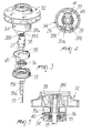
- FIG. 1 is a sectional view of a permanent-magnet electric motor coupled to a centrifugal pump by means of a device according to the invention in a first embodiment;
- FIG. 2 is an axial sectional view of the rotor, of the device and of the impeller of FIG. 1;
- FIG. 3 is an exploded perspective view of the device of the preceding figures;
- FIG. 4 is a transverse sectional view of the device of the preceding figures;
- FIG. 5 is an enlarged-scale axial sectional view of the device, taken along a plane which is perpendicular of the plane of the sectional view of FIG. 2;
- FIG. 6 is an axial sectional view of a rotor of a motor of the device according to the invention in a second embodiment and of an impeller of a centrifugal pump;
- FIG. 7 is an exploded perspective view of the device of FIG. 6;
- FIG. 8 is a transverse sectional view of the device of FIG. 6;
- FIG. 9 is an axial sectional view of the device according to the invention in a third embodiment and of an impeller of a centrifugal pump;
- FIG. 10 is an exploded perspective view of the device and of the impeller of FIG. 9;
- FIG. 11 is a transverse sectional view of the device of FIG. 9.
-
- With reference to the above FIGS. 1 to 5, said figures illustrate a permanent-magnet electric motor, generally designated by the
reference numeral 10, which comprises astator 11, with alamination pack 12 and windings (not shown), and arotor 14, which is arranged between two poles formed by saidlamination pack 12. - The
rotor 14 is constituted by an annular cylindricalpermanent magnet 16 whereon aplastic element 17 is overmolded, forming aninternal shank 17a andend flanges 17b. - The
rotor 14 accordingly has, as a whole, a cylindrical shape with anaxial hole 18 in which ashaft 19 is rigidly inserted. - The
shaft 19 is in turn supported by a cup-shaped element 20 (the chamber that contains the rotor 14) which belongs to astructure 21 for supporting theentire motor 10. - The cup-
shaped element 20 contains therotor 14, separating it from thestator 11. - The
shaft 19 is rotatably coupled, in the vicinity of theshaped bottom 22 of the cup-shaped element 20, to a bushing 25. - The seat for an
elastomeric ring 26 is formed between thebushing 25 and asimilar bushing 24 accommodated in thebottom 22. - Likewise,
bushings closure element 23 which is arranged at the opposite end, is fixed to the supportingstructure 21 and is crossed by theshaft 19; said bushings form, between them, the seat for anelastomeric ring 29. - The
bushing 28 is axially crossed by theshaft 19, which can rotate therein. - A thrust bearing, generally designated by the
reference numeral 30, is arranged between thebushing 28 and thecorresponding flange 17b. - According to the invention, between the
rotor 14, and accordingly between theshaft 19 rigidly coupled thereto, and the working part, which in this case is constituted by animpeller 32 of a centrifugal pump generally designated by thereference numeral 33 and coupled to theelectric motor 10, there is a motion transmission device which comprises, in this case, two motion transmission couplings which mutually cooperate in a kinematic series. - Advantageously, the motion transmission couplings are of the toothed type and comprise, in an axial
hollow body 34 which protrudes from theimpeller 32 toward therotor 14 and is closed by a cover 35 (preferably, but not necessarily, a hermetic seal is provided inside it, for example by gluing, gaskets, interference fit, ultrasonic welding, etcetera on the outer edge and an elastomeric lip-shaped ring 36 in the region where theshaft 19 passes), afirst tooth 37 which protrudes from atang 38 which is keyed to the end of theshaft 19. - The
shaft 19 in fact has, on its end, two diametrically oppositeflat regions 19a by means of which it couples to a complementarilyshaped hole 38a of thetang 38. - Axial fixing is achieved by means of
elastic hooks 38b of thetang 38 which enter an annular groove 19b of theshaft 19. - The
first tooth 37 is arranged eccentrically with respect to theshaft 19, has a limited radial extension and constitutes a driving tooth for asecond tooth 39 which protrudes axially from anannular element 40 which can rotate freely in thehollow body 34 with respect to theshaft 19 and to saidhollow body 34. - The
second tooth 39 is composed of an internal supportingpart 39a made of rigid plastics and of two mutually oppositeexternal parts 39b which are overmolded on the preceding one, are made of elastomer and form the contact surfaces. - The
second tooth 39 might of course also be provided monolithically without overmolding, using for example a hard elastomeric material. - The radial extension of the
second tooth 39 affects all of the region between thetang 38 and the outer wall of thehollow body 34, providing of course clearances which allow free movement or providing a slight interference (achieving a friction engagement) for example with a circumferential elastomeric element, not shown. - The
second tooth 39 has an axial extension which allows it to make contact with thefirst tooth 37 and with athird tooth 41 which protrudes radially from the internal wall of thehollow body 34 to the vicinity of the external profile of thefirst tooth 37. - The
second tooth 39 is therefore a tooth which is driven by thefirst tooth 37 and drives thethird tooth 41, interacting therewith through theelastomeric parts 39b. - The angle covered by the assembly constituted by the
first tooth 37 and by thesecond tooth 39 is smaller than a round angle and so is the angle covered by the assembly constituted by thesecond tooth 39 and by thethird tooth 41. - When the
electric motor 10 is actuated and therotor 14 begins its rotation, thefirst tooth 37, i.e., the tooth that is rigidly coupled thereto, starts to rotate; during its rotation it encounters thesecond tooth 39 and moves it. - Said second tooth, being moved, then encounters the
third tooth 41 and therefore at this point theimpeller 32, which is monolithic therewith, is turned. - Conveniently, it is possible to introduce in the hollow body 34 a fluid having an adequate viscosity with lubricating, impact-damping and noise-deadening functions.
- The motion transmission device is thus composed of two couplings which mutually cooperate in a kinematic series; a first one of said couplings is constituted by a driving element, which is eccentric with respect to the rotation axis (the first tooth 37) and is rigidly coupled to a component of the motion transmission system (the rotor 14), and by a driven element (the
second tooth 39 with thecorresponding part 39b), which is also eccentric with respect to the rotation axis and is rigidly coupled to the component arranged kinematically after the preceding one (the annular element 40). - A second one of these couplings is composed of a driving element (the
second tooth 39 with one of itsparts 39b), which is rigidly coupled to a component of the motion transmission system (the annular element 40), and of a driven element (the third tooth 41), which is rigidly coupled to the component of the motion transmission system that is arranged kinematically to follow (the impeller 32). - In practice it has been observed that coupling in a kinematic series two toothed motion transmission couplings increases the angle of freedom between the rotor and the working part (in this case, the impeller) that can currently be provided, and this has the beneficial effect of reducing the power currently required for starting in a permanent-magnet motor.
- This advantage accordingly allows to reduce the oversizing that is currently necessary to start loads having a particularly high inertia, as in the described case of a centrifugal pump.
- By designing the vanes of the impeller with a configuration which is not radial but has an adequate curvature, the power absorbed by the load (the impeller and the working fluid) in one direction of rotation (the direction in which the impeller has the lowest efficiency) is higher than the available power of the motor and is lower in the opposite direction of rotation (the direction in which the impeller has the highest efficiency).
- In the first case, the
impeller 32 loses its synchronization or pitch with respect to therotor 14, blocks and then automatically reverses its motion, while normal driving occurs in the second case. - Accordingly, a unidirectional motor has thus been obtained without any electric/electronic or mechanical device.
- With reference now to the above FIGS. 6 to 8, a second embodiment of the motion transmission device again has, between the
rotor 214, and consequently between theshaft 219 rigidly coupled thereto, and the working part, which in this case also is constituted by animpeller 232 of a centrifugal pump which is coupled to the electric motor, two toothed motion transmission couplings which comprise, in an axialhollow body 234 which is monolithic with theimpeller 232 and, in this case, is closed hermetically by acover 235 with a lip-shaped gasket 236, twofirst teeth 237 which protrude in diametrically opposite positions from a firstannular element 238 which is keyed to theshaft 219. - The
first teeth 237 are arranged eccentrically with respect to theshaft 219, have a limited radial extension and constitute driving teeth for twosecond teeth 239 which protrude axially from a secondannular element 240 which can rotate freely in thehollow body 234 with respect to theshaft 219 and to saidhollow body 234. - The
second teeth 239 also are diametrically mutually opposite. - The
first teeth 237 are arranged axially in offset positions and thesecond teeth 239 are shaped so as to haveparts 239a which protrude radially so as to affect all of the region between thetang 238 and the external wall of thehollow body 234, providing of course clearances which allow free movement or providing slight interference, producing a friction engagement, for example with a circumferential elastomeric element, not shown. - The
second teeth 239 have an axial extension which allows them to also make contact with twothird teeth 241 which are also diametrically opposite and protrude radially from the internal wall of thehollow body 234 in axially offset positions. - The
second teeth 239 are therefore teeth which are driven by thefirst teeth 237 and drive thethird teeth 241. - In this case, the parts, and therefore the masses, that rotate are arranged symmetrically with respect to the
shaft 219 and therefore rotation is balanced. - With reference to FIGS. 9, 10 and 11, a third embodiment of a motion transmission device has, between the
shaft 419 and the working part, which in this configuration also is theimpeller 432 of a centrifugal pump, two motion transmission couplings which mutually cooperate in a kinematic series. - In this case, said couplings are arranged inside an axial
hollow body 434 which protrudes from theimpeller 432 toward the rotor, which is not shown in the above figures for the sake of simplicity, and is closed by acover 435. - Preferably, said
cover 435 closes saidhollow body 434 by gluing, ultrasonic welding, or other methods, so as to ensure hermetic tightness internally. - In the region where the
shaft 419 passes through saidcover 435 there is a lip-shapedring 436 made of elastomeric material. - Inside the
hollow body 434 there is afirst tooth 437 which protrudes from atang 438 which is keyed to the end of theshaft 419. - Said end in fact has two diametrically opposite
flat regions 419a with which a complementarily shapedhole 438a of thetang 438 mates. - Said
first tooth 437 is eccentric with respect to theshaft 419 and has a limited axial extension; it constitutes a driving tooth for asecond tooth 439 which protrudes axially from anannular element 440 which can rotate freely, inside thehollow body 434, with respect to theshaft 419. - Said
second tooth 439 has an internal supportingpart 439a made of rigid plastics which is monolithic with theannular element 440, which in this case has a substantially cylindrical structure, and is embedded in the remaining part 439b made of elastomeric material, which is overmolded on the preceding one and forms the contact surfaces. - In this case also, said
third tooth 439 might be provided monolithically. - The radial extension of said
second tooth 439 affects all of the region between thetang 438 and the internal wall of thehollow body 434. - Clearances are of course provided which allow free motion or, as an alternative, there is a slight interference which produces friction engagement, for example by resorting to a circumferential element made of elastomeric material which is not shown for the sake of simplicity.
- Said
second tooth 439 has an axial extension which allows it to make contact with saidfirst tooth 437 and with a third tooth, now designated by thereference numeral 441, which protrudes axially from saidcover 435 from a position which is proximate to the outer profile of the face that is directed toward the inside of thehollow body 434. - In particular, the axial extension of said
third tooth 441 is such that it can make contact only with the elastomeric external parts 439b of thesecond tooth 439 but cannot make contact with saidfirst tooth 437. - Said
second tooth 439 is accordingly driven by thefirst tooth 437 and in turn drives saidthird tooth 441 by means of the elastomeric parts 439b. - The angle covered by the assembly constituted by the
first tooth 437 and by thesecond tooth 439 is less than a round angle and so is the angle covered by thesecond tooth 439 together with saidthird tooth 441. - When the motor is started, the
first tooth 437 therefore starts to rotate rigidly with the rotor until it encounters, during its rotation, thesecond tooth 439, which it moves. - Said second tooth therefore starts to rotate concordantly with the rotor until it encounters said
third tooth 441, which is rigidly coupled to thehollow body 434 and accordingly to theimpeller 432, which is therefore turned. - In practice it has been observed that in all its embodiments the invention has achieved the intended aim and objects.
- The invention thus conceived is susceptible of numerous modifications and variations, all of which are within the scope of the inventive concept.
- All the details may also be replaced with other technically equivalent elements.
- In practice, the materials employed, so long as they are compatible with the contingent use, as well as the dimensions, may be any according to requirements.
- The disclosures in Italian Patent Application No. PD98A000058 from which this application claims priority are incorporated herein by reference.
Claims (12)
- A device for transmitting motion between a rotor (14, 214) of a synchronous permanent-magnet motor (10) and a working part (32, 232, 432), comprising:at least two motion transmission couplings which mutually cooperate in a kinematic series;a first coupling of said motion transmission couplings comprising at least one driving element (37, 237, 437) which is eccentric with respect to the rotation axis and is rigidly coupled to the rotor (14, 214) and at least one driven element (39, 239, 439) which is also eccentric with respect to the rotation axis and can rotate freely with respect to said rotor;a second coupling of said motion transmission couplings comprising at least one driving element (39, 239, 439) which is eccentric with respect to the rotation axis and one driven element (41, 241, 441) which is also eccentric with respect to the rotation axis and is rigidly coupled to the working part (32, 232, 432); characterized in thatthe angle covered by the elements of each coupling being, as a whole, less than a round angle;said at least one driving element of the second coupling being said at least one driven element of said first coupling, so that the angle of freedom between the rotor and the working part is increased;said first coupling comprises two first teeth (237) which are rigidly coupled to the rotor (214) of a motor in diametrically opposite positions, and two second teeth (239) which are rigidly coupled, likewise in diametrically opposite positions, to an annular element (240) which can rotate freely with respect to said rotor, said second coupling comprising said second teeth (239) and two third teeth (241) which are also diametrically opposite and are rigidly coupled to the working part (232).
- The device according to claim 1, characterized in that said motion transmission couplings are arranged in an axial hollow body (34) which is rigidly coupled to said working part (32) and is closed by a cover (35).
- The device according to claim 2, characterized in that said first tooth (37) protrudes from a tang (38) which is keyed on the end of said shaft (19), said first tooth (37) being arranged eccentrically with respect to said shaft (19) and constituting a driving tooth far said second tooth (39) which protrudes axially from an annular element (40) which can rotate freely in said hollow body (34) with respect to said shaft (19) and to said hollow body (34), said second tooth (39) having an extension which allows it to make contact with said first tooth (37) and with said third tooth (41) which protrudes from the internal wall of the hollow body (34).
- The device according to claim 3, characterized in that said first tooth (37) has a radial extension which partially affects the internal space of said hollow body (34), the radial extension of said second tooth (39) affecting the region between said tang (38) and the external wall of said hollow body (34), providing clearances which allow free movement, said second tooth (39) having an axial extension which allows it to make contact with said first tooth (37) and with said third tooth (41), said third tooth (41) protruding radially from the internal wall of said hollow body (34) to the vicinity of the external profile of said first tooth (37).
- The device according to claim 1, characterized in that said couplings are arranged in an axial hollow body (234) which is rigidly coupled to said working part (232) and is closed hermetically by a cover (235).
- The device according to claim 1, characterized in that said two first teeth (237) protrude in a diametrically mutually apposite configuration from a first annular element (238) which is keyed to the shaft (219) of a molar, said first teeth (237) radially and partially affecting the space inside said hollow body (234), said first teeth (237) constituting driving teeth far said two second teeth (239) which protrude axially from a second annular element (240) which can rotate freely in said hollow body (234) with respect to said shaft (219) and to said hollow body (234), said second teeth (239) having an extension which allows them to make contact also with two third teeth (241) which protrude radially from the internal wall of said hollow body (234) in the region left free by said first teeth (237).
- The device according to claim 6, characterized in that said first teeth (237) are arranged in axially offset positions and in that said second teeth (239) are shaped so as to have parts whose radial extension affects all of the region between said annular element (238) and the external wall of the hollow body (234), providing clearances which allow free movement, said second teeth (239) having an axial extension which allows them to make contact with said first teeth (237) and with said third teeth (241) which protrude radially from the internal wall of said hollow (234) in axially offset positions.
- The device according to one or more of the preceding claims, characterized in that at least one of said teeth (39) is composed of an internal supporting part (39a) which is made of rigid plastics and of two mutually apposite external parts (39b) which are overmolded on the internal part (39a), are made of elastomeric material, and form the surfaces for contact with the other teeth.
- The device according to one or more of the preceding claims, characterized in that a slight interference is provided between the mutually moving parts, producing a friction engagement.
- The device according to claim 1, characterized in that said first tooth (37) protrudes from an annular element (38) which is keyed to the end of said shaft (19), said first tooth (37) being arranged eccentrically with respect to said shaft (19) and constituting a driving tooth for said second tooth (39) which protrudes axially from an annular element (40) which can rotate freely in said hollow body (34) with respect to said shaft (19) and to said hollow body (34), said second tooth (39) having an extension which allows it to make contact with said first tooth (37) and with said third tooth (41) which protrudes from the face of said cover (35) which is directed toward the inside of the hollow body (34).
- The device according to claim 10, characterized in that said first tooth (37) has a radial extension which partially affects the internal space of said hollow body (34), the radial extension of said second tooth (39). affecting the region between said tang (38) and the external wall of said hollow body (34), providing clearances which allow free movement, said second tooth (39) having an axial extension which allows it to make contact with said first tooth (37) and with said third tooth (41), said third tooth (41) protruding radially from a position which is proximate to the external profile of the cover (35) to the vicinity of the external profile of said annular element (40).
- The device according to one or more of the preceding claims, characterized in that said working part is an impeller (32,232,432) with curved vanes of a centrifugal pump.
Priority Applications (1)
| Application Number | Priority Date | Filing Date | Title |
|---|---|---|---|
| EP07006832.5A EP1801954B1 (en) | 1998-03-19 | 1999-03-16 | A centrifugal pump driven by a synchronous electric motor |
Applications Claiming Priority (3)
| Application Number | Priority Date | Filing Date | Title |
|---|---|---|---|
| ITPD980058 | 1998-03-19 | ||
| IT98PD000058A ITPD980058A1 (en) | 1998-03-19 | 1998-03-19 | DRIVING DEVICE, WITH WIDE ROTATION ANGLE BETWEEN THE SYNCHRONOUS PERMANENT MAGNET MOTOR AND THE OPERATING BODY |
| EP99910348A EP0983630B1 (en) | 1998-03-19 | 1999-03-16 | Device for transmitting motion between the rotor of a synchronous permanent-magnet motor and a working part, said device having an increased free rotation angle |
Related Parent Applications (2)
| Application Number | Title | Priority Date | Filing Date |
|---|---|---|---|
| EP99910348A Division EP0983630B1 (en) | 1998-03-19 | 1999-03-16 | Device for transmitting motion between the rotor of a synchronous permanent-magnet motor and a working part, said device having an increased free rotation angle |
| EP99910348.4 Division | 1999-03-16 |
Related Child Applications (2)
| Application Number | Title | Priority Date | Filing Date |
|---|---|---|---|
| EP07006832.5A Division EP1801954B1 (en) | 1998-03-19 | 1999-03-16 | A centrifugal pump driven by a synchronous electric motor |
| EP07006832.5 Division-Into | 2007-04-02 |
Publications (2)
| Publication Number | Publication Date |
|---|---|
| EP1372245A1 true EP1372245A1 (en) | 2003-12-17 |
| EP1372245B1 EP1372245B1 (en) | 2013-10-23 |
Family
ID=11392107
Family Applications (3)
| Application Number | Title | Priority Date | Filing Date |
|---|---|---|---|
| EP03017761.2A Expired - Lifetime EP1372245B1 (en) | 1998-03-19 | 1999-03-16 | Device for transmitting motion between the rotor of a synchronous permanent-magnet motor and the working part, said device having an increased free rotation angle |
| EP99910348A Revoked EP0983630B1 (en) | 1998-03-19 | 1999-03-16 | Device for transmitting motion between the rotor of a synchronous permanent-magnet motor and a working part, said device having an increased free rotation angle |
| EP07006832.5A Expired - Lifetime EP1801954B1 (en) | 1998-03-19 | 1999-03-16 | A centrifugal pump driven by a synchronous electric motor |
Family Applications After (2)
| Application Number | Title | Priority Date | Filing Date |
|---|---|---|---|
| EP99910348A Revoked EP0983630B1 (en) | 1998-03-19 | 1999-03-16 | Device for transmitting motion between the rotor of a synchronous permanent-magnet motor and a working part, said device having an increased free rotation angle |
| EP07006832.5A Expired - Lifetime EP1801954B1 (en) | 1998-03-19 | 1999-03-16 | A centrifugal pump driven by a synchronous electric motor |
Country Status (8)
| Country | Link |
|---|---|
| US (4) | USRE39481E1 (en) |
| EP (3) | EP1372245B1 (en) |
| AT (1) | ATE252287T1 (en) |
| AU (1) | AU2933499A (en) |
| DE (1) | DE69912051T2 (en) |
| ES (2) | ES2436394T3 (en) |
| IT (1) | ITPD980058A1 (en) |
| WO (1) | WO1999048189A1 (en) |
Cited By (4)
| Publication number | Priority date | Publication date | Assignee | Title |
|---|---|---|---|---|
| DE102004051400A1 (en) * | 2004-10-21 | 2006-04-27 | Siemens Ag | Axial bearing for rotor, has bearing seat comprising damping unit, where openings of seat face spiral housing, disk arranged slantwise to spiral housing comprise recesses on its external radial boundary, and bearing rubber stop in housing |
| DE102004051398A1 (en) * | 2004-10-21 | 2006-04-27 | Siemens Ag | Axial bearing for rotor, has bearing carrier arranged on drive shaft such that its opening faces spiral housing, and bearing disc pressing with its outer radial boundary in projection, and fitting its side to bearing stopper |
| US7824162B2 (en) | 2004-08-19 | 2010-11-02 | Edwards Limited | Vacuum pump |
| EP2025944B1 (en) | 2007-08-09 | 2017-08-09 | Askoll Holding S.r.l. | Mono-phase syncronous electric motorfor household appliances |
Families Citing this family (32)
| Publication number | Priority date | Publication date | Assignee | Title |
|---|---|---|---|---|
| ITPD20010256A1 (en) * | 2001-10-30 | 2003-04-30 | Askoll Holding Srl | PERFECTED DRIVING DEVICE BETWEEN THE ROTOR OF A SYNCHRONOUS MOTOR WITH PERMANENT MAGNETS AND THE OPERATING BODY. |
| DE60125244T2 (en) * | 2000-07-06 | 2007-06-28 | Askoll Holding S.R.L., Povolaro Di Dueville | Monodirectional impeller for electric centrifugal pumps |
| DE60334891D1 (en) * | 2002-03-21 | 2010-12-23 | Arcelik As | PUMP |
| DE60306594T2 (en) * | 2002-09-03 | 2006-11-16 | Emerson Appliance Motors Europe S.R.L., Moncalieri | Centrifugal pump for household appliances |
| ITPN20020096A1 (en) * | 2002-12-10 | 2004-06-11 | Electrolux Home Products Corporatio N N V | WASHING MACHINE WITH PERFECTED ASYNCHRONOUS MOTOR. |
| DE10308090B4 (en) * | 2003-02-24 | 2005-12-22 | Hanning Elektro-Werke Gmbh & Co. Kg | Synchronous motor with start-up device |
| DE10337621B4 (en) * | 2003-08-16 | 2007-10-25 | Daimlerchrysler Ag | Method for updating a digital map |
| CN100465455C (en) * | 2003-11-26 | 2009-03-04 | 普拉塞特股份有限公司 | Centrifugal pump especially for domestic appliances and other similar products |
| EP1553681B1 (en) * | 2003-12-31 | 2017-03-15 | Askoll Holding S.r.l. | Coupling device between a rotor of a permanent-magnet synchronous motor and a working part |
| EP1578006A2 (en) * | 2004-03-15 | 2005-09-21 | Nidec Shibaura Corporation | Starting device for a synchronous motor |
| DE112005000073T5 (en) * | 2004-06-24 | 2006-08-24 | Lg Electronics Inc. | Leak prevention construction of a dishwasher |
| EP1612427B1 (en) * | 2004-06-30 | 2009-02-25 | Askoll Holding S.r.l. | Axial thrust-bearing for electric motor pump |
| DE102004056508B3 (en) * | 2004-11-24 | 2006-03-09 | Hanning Elektro-Werke Gmbh & Co. Kg | A coupling for synchronous electric motors has a flexible roller between the outer cylinder and shaft which has a progressive ramp to trap the flexible cylinder |
| US20070031265A1 (en) * | 2005-08-04 | 2007-02-08 | Cavouras Gregory J | Valve and pump devices for expelling fluid from vessels |
| DE602006017481D1 (en) | 2005-08-30 | 2010-11-25 | Askoll Holding Srl | Two-phase permanent magnet synchronous motor with mechanical starting aid for washing machines and similar household appliances, especially for washing pumps |
| CN2916195Y (en) * | 2006-01-26 | 2007-06-27 | 江门市汉宇电器有限公司 | Centrifugal drainage pump |
| US7692353B2 (en) * | 2006-08-11 | 2010-04-06 | Askoll Holding S.R.L. | Permanent-magnet two-phase synchronous electric motor with mechanical start-up for washing machines and similar household appliances, in particular for washing pumps |
| DE202006020761U1 (en) * | 2006-09-28 | 2010-05-20 | Hanning Elektro-Werke Gmbh & Co. Kg | Drive device, in particular for a pump |
| CN101153604B (en) * | 2006-09-29 | 2011-04-13 | 德昌电机股份有限公司 | Pump impeller connecting mechanism with limited free motion |
| PL2006976T3 (en) | 2007-06-18 | 2013-05-31 | Askoll Holding Srl | Two-phase synchronous electric motor |
| PL2042074T3 (en) * | 2007-09-27 | 2011-04-29 | Electrolux Home Products Corp Nv | Rotary pump, in particular for dishwashers or washing machines |
| CN101408228B (en) * | 2008-09-11 | 2011-01-26 | 江门市汉宇电器有限公司 | Transmission device between working component and rotor of permanent magnetism synchronous electric machine |
| KR101608647B1 (en) | 2008-12-02 | 2016-04-04 | 엘지전자 주식회사 | Drain pump of washing machine |
| JP5122535B2 (en) * | 2009-03-27 | 2013-01-16 | 株式会社 イマジナホールディングス | Angular vibration centrifugal pump |
| DE102009055196A1 (en) | 2009-12-22 | 2011-06-30 | Hanning Elektro-Werke GmbH & Co. KG, 33813 | Method for driving e.g. drain pump, utilized for pumping out water from e.g. washing machine, involves starting rotor of motor above maximum starting angle without engagement with coupling parts such that parts are engaged with each other |
| CN102545466B (en) * | 2010-11-10 | 2015-11-25 | 德昌电机(深圳)有限公司 | Electric machine |
| US20130022467A1 (en) * | 2011-07-20 | 2013-01-24 | Derek Lee Watkins | Rotor assembly including a biasing mechanism |
| US9399996B2 (en) * | 2011-07-20 | 2016-07-26 | General Electric Company | Cam plate and an appliance including the cam plate |
| JP5861474B2 (en) * | 2012-01-30 | 2016-02-16 | セイコーエプソン株式会社 | Pump device |
| CN106249827B (en) * | 2016-07-25 | 2023-04-28 | 东莞市真品科技有限公司 | CPU water pump radiator |
| TWI674736B (en) * | 2018-05-09 | 2019-10-11 | 建準電機工業股份有限公司 | Motor rotor |
| CN113323899A (en) * | 2021-06-02 | 2021-08-31 | 浙江吉利控股集团有限公司 | Bilateral air quantity adjustable fan and air conditioner |
Citations (5)
| Publication number | Priority date | Publication date | Assignee | Title |
|---|---|---|---|---|
| GB2177456A (en) * | 1985-07-01 | 1987-01-21 | Easthorpe Investments Ltd | Centrifugal pump |
| EP0213751A1 (en) * | 1985-07-30 | 1987-03-11 | Advanced Cardiovascular Systems, Inc. | Steerable dilatation catheter with rotation limiting device |
| US4661085A (en) * | 1985-09-09 | 1987-04-28 | Philips Home Products, Inc. | Lost motion clutch assembly |
| US4803855A (en) * | 1987-08-10 | 1989-02-14 | Whirlpool Corporation | Single shaft agitate and spin drive for automatic washer |
| EP0723329A2 (en) * | 1995-01-19 | 1996-07-24 | ASKOLL S.p.A. | Improved startup device for the rotor of a permanent-magnet synchronous motor |
Family Cites Families (14)
| Publication number | Priority date | Publication date | Assignee | Title |
|---|---|---|---|---|
| FR965022A (en) * | 1950-08-31 | |||
| US1627964A (en) * | 1925-03-24 | 1927-05-10 | Nat Automatic Tool Co | Lost-motion coupling |
| US2099359A (en) * | 1935-10-08 | 1937-11-16 | Woodeson William Armstrong | Means for driving rotary members |
| US4750872A (en) * | 1985-07-01 | 1988-06-14 | Easthorpe Investments Ltd. | Centrifugal pump with damped motor connection |
| IT1218569B (en) * | 1987-04-22 | 1990-04-19 | Askoll Srl | CENTRIFIGE PUMP PERFECT FOR WASHING MACHINES, DISHWASHER AND APPLIANCES IN GENERAL |
| EP0487785B1 (en) | 1990-11-30 | 1994-05-25 | Siemens Aktiengesellschaft | Connection for a pump impeller |
| FR2676510B1 (en) | 1991-05-14 | 1995-01-06 | Electro Mec Nivernais | QUIET CENTRIFUGAL MOTOR PUMP. |
| DE9302945U1 (en) * | 1993-03-01 | 1993-11-11 | Hanning Elektro Werke | Synchronous motor equipped with a start-up aid |
| DE9421026U1 (en) * | 1994-01-13 | 1995-05-18 | Bosch Gmbh Robert | Drive for an electrical machine, in particular a generator |
| DE4424996A1 (en) * | 1994-07-15 | 1996-01-18 | Oase Pumpen | Centrifugal pump, especially for fountains |
| ITPD980003A1 (en) * | 1998-01-08 | 1999-07-08 | Askoll Holding Srl | ONE-WAY DRIVING JOINT BETWEEN THE ROTOR OF A PERMANENT MAGNET SYNCHRONOUS MOTOR AND THE OPERATING ORGAN |
| IT245149Y1 (en) * | 1998-03-27 | 2002-03-19 | Tecnocomponenti Srl | SYNCHRONOUS ELECTRIC PUMP EQUIPPED WITH SOUNDPROOFING DEVICE |
| US6210116B1 (en) * | 1998-11-05 | 2001-04-03 | John E. Kuczaj | High efficiency pump impeller |
| US6478555B1 (en) * | 1999-06-16 | 2002-11-12 | Lg Electronics, Inc. | Apparatus for controlling noise and vibration for drain pump |
-
1998
- 1998-03-19 IT IT98PD000058A patent/ITPD980058A1/en unknown
-
1999
- 1999-03-16 WO PCT/EP1999/001715 patent/WO1999048189A1/en active IP Right Grant
- 1999-03-16 US US10/841,426 patent/USRE39481E1/en not_active Expired - Lifetime
- 1999-03-16 EP EP03017761.2A patent/EP1372245B1/en not_active Expired - Lifetime
- 1999-03-16 AU AU29334/99A patent/AU2933499A/en not_active Abandoned
- 1999-03-16 EP EP99910348A patent/EP0983630B1/en not_active Revoked
- 1999-03-16 DE DE69912051T patent/DE69912051T2/en not_active Revoked
- 1999-03-16 AT AT99910348T patent/ATE252287T1/en not_active IP Right Cessation
- 1999-03-16 US US09/423,544 patent/US6384508B1/en not_active Ceased
- 1999-03-16 ES ES03017761T patent/ES2436394T3/en not_active Expired - Lifetime
- 1999-03-16 ES ES99910348T patent/ES2207188T3/en not_active Expired - Lifetime
- 1999-03-16 EP EP07006832.5A patent/EP1801954B1/en not_active Expired - Lifetime
-
2002
- 2002-03-21 US US10/101,752 patent/US20020122688A1/en not_active Abandoned
-
2005
- 2005-02-14 US US11/057,676 patent/US7097434B2/en not_active Expired - Lifetime
Patent Citations (5)
| Publication number | Priority date | Publication date | Assignee | Title |
|---|---|---|---|---|
| GB2177456A (en) * | 1985-07-01 | 1987-01-21 | Easthorpe Investments Ltd | Centrifugal pump |
| EP0213751A1 (en) * | 1985-07-30 | 1987-03-11 | Advanced Cardiovascular Systems, Inc. | Steerable dilatation catheter with rotation limiting device |
| US4661085A (en) * | 1985-09-09 | 1987-04-28 | Philips Home Products, Inc. | Lost motion clutch assembly |
| US4803855A (en) * | 1987-08-10 | 1989-02-14 | Whirlpool Corporation | Single shaft agitate and spin drive for automatic washer |
| EP0723329A2 (en) * | 1995-01-19 | 1996-07-24 | ASKOLL S.p.A. | Improved startup device for the rotor of a permanent-magnet synchronous motor |
Cited By (6)
| Publication number | Priority date | Publication date | Assignee | Title |
|---|---|---|---|---|
| US7824162B2 (en) | 2004-08-19 | 2010-11-02 | Edwards Limited | Vacuum pump |
| DE102004051400A1 (en) * | 2004-10-21 | 2006-04-27 | Siemens Ag | Axial bearing for rotor, has bearing seat comprising damping unit, where openings of seat face spiral housing, disk arranged slantwise to spiral housing comprise recesses on its external radial boundary, and bearing rubber stop in housing |
| DE102004051398A1 (en) * | 2004-10-21 | 2006-04-27 | Siemens Ag | Axial bearing for rotor, has bearing carrier arranged on drive shaft such that its opening faces spiral housing, and bearing disc pressing with its outer radial boundary in projection, and fitting its side to bearing stopper |
| DE102004051400B4 (en) * | 2004-10-21 | 2019-02-21 | Continental Automotive Gmbh | Thrust bearing for a rotor |
| DE102004051398B4 (en) * | 2004-10-21 | 2019-02-21 | Continental Automotive Gmbh | Thrust bearing for a rotor |
| EP2025944B1 (en) | 2007-08-09 | 2017-08-09 | Askoll Holding S.r.l. | Mono-phase syncronous electric motorfor household appliances |
Also Published As
| Publication number | Publication date |
|---|---|
| US20020122688A1 (en) | 2002-09-05 |
| ES2436394T3 (en) | 2013-12-30 |
| EP1801954A2 (en) | 2007-06-27 |
| EP1801954A3 (en) | 2008-12-03 |
| ITPD980058A1 (en) | 1999-09-19 |
| USRE39481E1 (en) | 2007-01-30 |
| EP0983630B1 (en) | 2003-10-15 |
| US7097434B2 (en) | 2006-08-29 |
| DE69912051D1 (en) | 2003-11-20 |
| US20050147510A1 (en) | 2005-07-07 |
| EP1801954B1 (en) | 2013-05-22 |
| AU2933499A (en) | 1999-10-11 |
| ATE252287T1 (en) | 2003-11-15 |
| DE69912051T2 (en) | 2004-07-29 |
| WO1999048189A1 (en) | 1999-09-23 |
| EP1372245B1 (en) | 2013-10-23 |
| US6384508B1 (en) | 2002-05-07 |
| ES2207188T3 (en) | 2004-05-16 |
| EP0983630A1 (en) | 2000-03-08 |
Similar Documents
| Publication | Publication Date | Title |
|---|---|---|
| EP1372245B1 (en) | Device for transmitting motion between the rotor of a synchronous permanent-magnet motor and the working part, said device having an increased free rotation angle | |
| EP1365157B1 (en) | Monodirectional impeller for centrifugal electric pump having a permanent-magnet synchronous motor | |
| JPH08242565A (en) | Improved starter for rotor of permanent magnet synchronous motor and centrifugal pump containing it | |
| JP2007024035A (en) | Pump | |
| EP0966612B1 (en) | Direction-dependent driving coupling between the rotor of a permanent-magnet synchronous motor and the working part | |
| US20050111992A1 (en) | Centrifugal pump for electrical household appliance or the like | |
| US6335579B1 (en) | Electric motor with permanent-magnet rotor having viscous shaft coupling | |
| US6972502B2 (en) | Device for transmitting motion between the rotor of a synchronous permanent-magnet motor and a working part | |
| EP1571252A1 (en) | Electric motor-driven pump for washing machines and the like | |
| US20090155066A1 (en) | Pump Driving Apparatus | |
| RU2360350C2 (en) | Connector assembly | |
| US20060153714A1 (en) | Brushless motor pump | |
| KR102472014B1 (en) | motor and fan device having the same | |
| US9148039B2 (en) | Motor assembly | |
| JP2008283780A (en) | Clutch mechanism of rotary machine | |
| ITPD970124A1 (en) | ELECTRIC MOTOR WITH PERMANENT MAGNET ROTOR COUPLED TO THE AXIS IN A VISCOUS MODE |
Legal Events
| Date | Code | Title | Description |
|---|---|---|---|
| PUAI | Public reference made under article 153(3) epc to a published international application that has entered the european phase |
Free format text: ORIGINAL CODE: 0009012 |
|
| AC | Divisional application: reference to earlier application |
Ref document number: 0983630 Country of ref document: EP Kind code of ref document: P |
|
| AK | Designated contracting states |
Kind code of ref document: A1 Designated state(s): AT BE CH DE ES FR GB IT LI NL SE |
|
| 17P | Request for examination filed |
Effective date: 20040615 |
|
| AKX | Designation fees paid |
Designated state(s): AT BE CH DE ES FR GB IT LI NL SE |
|
| GRAP | Despatch of communication of intention to grant a patent |
Free format text: ORIGINAL CODE: EPIDOSNIGR1 |
|
| GRAS | Grant fee paid |
Free format text: ORIGINAL CODE: EPIDOSNIGR3 |
|
| GRAJ | Information related to disapproval of communication of intention to grant by the applicant or resumption of examination proceedings by the epo deleted |
Free format text: ORIGINAL CODE: EPIDOSDIGR1 |
|
| 17Q | First examination report despatched |
Effective date: 20070709 |
|
| APBK | Appeal reference recorded |
Free format text: ORIGINAL CODE: EPIDOSNREFNE |
|
| APBN | Date of receipt of notice of appeal recorded |
Free format text: ORIGINAL CODE: EPIDOSNNOA2E |
|
| APBR | Date of receipt of statement of grounds of appeal recorded |
Free format text: ORIGINAL CODE: EPIDOSNNOA3E |
|
| APAF | Appeal reference modified |
Free format text: ORIGINAL CODE: EPIDOSCREFNE |
|
| APBX | Invitation to file observations in appeal sent |
Free format text: ORIGINAL CODE: EPIDOSNOBA2E |
|
| APBT | Appeal procedure closed |
Free format text: ORIGINAL CODE: EPIDOSNNOA9E |
|
| GRAP | Despatch of communication of intention to grant a patent |
Free format text: ORIGINAL CODE: EPIDOSNIGR1 |
|
| INTG | Intention to grant announced |
Effective date: 20130711 |
|
| GRAS | Grant fee paid |
Free format text: ORIGINAL CODE: EPIDOSNIGR3 |
|
| GRAA | (expected) grant |
Free format text: ORIGINAL CODE: 0009210 |
|
| AC | Divisional application: reference to earlier application |
Ref document number: 0983630 Country of ref document: EP Kind code of ref document: P |
|
| AK | Designated contracting states |
Kind code of ref document: B1 Designated state(s): AT BE CH DE ES FR GB IT LI NL SE |
|
| REG | Reference to a national code |
Ref country code: GB Ref legal event code: FG4D |
|
| REG | Reference to a national code |
Ref country code: CH Ref legal event code: EP |
|
| REG | Reference to a national code |
Ref country code: AT Ref legal event code: REF Ref document number: 638021 Country of ref document: AT Kind code of ref document: T Effective date: 20131115 |
|
| REG | Reference to a national code |
Ref country code: DE Ref legal event code: R096 Ref document number: 69944914 Country of ref document: DE Effective date: 20131212 |
|
| REG | Reference to a national code |
Ref country code: ES Ref legal event code: FG2A Ref document number: 2436394 Country of ref document: ES Kind code of ref document: T3 Effective date: 20131230 |
|
| REG | Reference to a national code |
Ref country code: NL Ref legal event code: VDEP Effective date: 20131023 |
|
| REG | Reference to a national code |
Ref country code: AT Ref legal event code: MK05 Ref document number: 638021 Country of ref document: AT Kind code of ref document: T Effective date: 20131023 |
|
| PG25 | Lapsed in a contracting state [announced via postgrant information from national office to epo] |
Ref country code: NL Free format text: LAPSE BECAUSE OF FAILURE TO SUBMIT A TRANSLATION OF THE DESCRIPTION OR TO PAY THE FEE WITHIN THE PRESCRIBED TIME-LIMIT Effective date: 20131023 Ref country code: BE Free format text: LAPSE BECAUSE OF FAILURE TO SUBMIT A TRANSLATION OF THE DESCRIPTION OR TO PAY THE FEE WITHIN THE PRESCRIBED TIME-LIMIT Effective date: 20131023 Ref country code: SE Free format text: LAPSE BECAUSE OF FAILURE TO SUBMIT A TRANSLATION OF THE DESCRIPTION OR TO PAY THE FEE WITHIN THE PRESCRIBED TIME-LIMIT Effective date: 20131023 |
|
| PG25 | Lapsed in a contracting state [announced via postgrant information from national office to epo] |
Ref country code: AT Free format text: LAPSE BECAUSE OF FAILURE TO SUBMIT A TRANSLATION OF THE DESCRIPTION OR TO PAY THE FEE WITHIN THE PRESCRIBED TIME-LIMIT Effective date: 20131023 |
|
| REG | Reference to a national code |
Ref country code: DE Ref legal event code: R097 Ref document number: 69944914 Country of ref document: DE |
|
| PLBE | No opposition filed within time limit |
Free format text: ORIGINAL CODE: 0009261 |
|
| STAA | Information on the status of an ep patent application or granted ep patent |
Free format text: STATUS: NO OPPOSITION FILED WITHIN TIME LIMIT |
|
| 26N | No opposition filed |
Effective date: 20140724 |
|
| REG | Reference to a national code |
Ref country code: CH Ref legal event code: PL |
|
| REG | Reference to a national code |
Ref country code: DE Ref legal event code: R097 Ref document number: 69944914 Country of ref document: DE Effective date: 20140724 |
|
| GBPC | Gb: european patent ceased through non-payment of renewal fee |
Effective date: 20140316 |
|
| PG25 | Lapsed in a contracting state [announced via postgrant information from national office to epo] |
Ref country code: CH Free format text: LAPSE BECAUSE OF NON-PAYMENT OF DUE FEES Effective date: 20140331 Ref country code: GB Free format text: LAPSE BECAUSE OF NON-PAYMENT OF DUE FEES Effective date: 20140316 Ref country code: LI Free format text: LAPSE BECAUSE OF NON-PAYMENT OF DUE FEES Effective date: 20140331 |
|
| REG | Reference to a national code |
Ref country code: FR Ref legal event code: PLFP Year of fee payment: 18 |
|
| REG | Reference to a national code |
Ref country code: FR Ref legal event code: PLFP Year of fee payment: 19 |
|
| REG | Reference to a national code |
Ref country code: FR Ref legal event code: PLFP Year of fee payment: 20 |
|
| PGFP | Annual fee paid to national office [announced via postgrant information from national office to epo] |
Ref country code: DE Payment date: 20180219 Year of fee payment: 20 |
|
| PGFP | Annual fee paid to national office [announced via postgrant information from national office to epo] |
Ref country code: IT Payment date: 20180219 Year of fee payment: 20 Ref country code: FR Payment date: 20180220 Year of fee payment: 20 |
|
| PGFP | Annual fee paid to national office [announced via postgrant information from national office to epo] |
Ref country code: ES Payment date: 20180403 Year of fee payment: 20 |
|
| REG | Reference to a national code |
Ref country code: DE Ref legal event code: R071 Ref document number: 69944914 Country of ref document: DE |
|
| REG | Reference to a national code |
Ref country code: ES Ref legal event code: FD2A Effective date: 20200904 |
|
| PG25 | Lapsed in a contracting state [announced via postgrant information from national office to epo] |
Ref country code: ES Free format text: LAPSE BECAUSE OF EXPIRATION OF PROTECTION Effective date: 20190317 |