EP0780833A2 - Verbessertes Magnetaufzeichnungssystem mit sättigbarer Schichte und gebrauchmachend von MR-Elementen - Google Patents
Verbessertes Magnetaufzeichnungssystem mit sättigbarer Schichte und gebrauchmachend von MR-Elementen Download PDFInfo
- Publication number
- EP0780833A2 EP0780833A2 EP96119146A EP96119146A EP0780833A2 EP 0780833 A2 EP0780833 A2 EP 0780833A2 EP 96119146 A EP96119146 A EP 96119146A EP 96119146 A EP96119146 A EP 96119146A EP 0780833 A2 EP0780833 A2 EP 0780833A2
- Authority
- EP
- European Patent Office
- Prior art keywords
- head
- magnetic
- recording system
- layer
- magnetic recording
- Prior art date
- Legal status (The legal status is an assumption and is not a legal conclusion. Google has not performed a legal analysis and makes no representation as to the accuracy of the status listed.)
- Withdrawn
Links
- 238000001514 detection method Methods 0.000 title abstract description 8
- 238000003860 storage Methods 0.000 claims abstract description 51
- 230000004907 flux Effects 0.000 claims description 35
- 239000000696 magnetic material Substances 0.000 claims description 12
- 238000002955 isolation Methods 0.000 claims description 6
- 229910000702 sendust Inorganic materials 0.000 claims description 3
- 229910045601 alloy Inorganic materials 0.000 claims description 2
- 239000000956 alloy Substances 0.000 claims description 2
- 229910000531 Co alloy Inorganic materials 0.000 claims 1
- 230000035945 sensitivity Effects 0.000 abstract description 9
- 230000002829 reductive effect Effects 0.000 abstract description 6
- 229920006395 saturated elastomer Polymers 0.000 description 14
- 230000035699 permeability Effects 0.000 description 13
- 230000008901 benefit Effects 0.000 description 9
- 238000000034 method Methods 0.000 description 9
- 230000001939 inductive effect Effects 0.000 description 8
- 230000000694 effects Effects 0.000 description 7
- 125000006850 spacer group Chemical group 0.000 description 7
- 238000013461 design Methods 0.000 description 6
- 238000004519 manufacturing process Methods 0.000 description 6
- 239000000758 substrate Substances 0.000 description 6
- 238000005516 engineering process Methods 0.000 description 5
- 230000006870 function Effects 0.000 description 5
- 230000006872 improvement Effects 0.000 description 5
- 239000000463 material Substances 0.000 description 5
- 229910000859 α-Fe Inorganic materials 0.000 description 5
- 230000008859 change Effects 0.000 description 4
- 230000001965 increasing effect Effects 0.000 description 4
- 239000010409 thin film Substances 0.000 description 4
- 230000007704 transition Effects 0.000 description 4
- 230000009467 reduction Effects 0.000 description 3
- 230000002463 transducing effect Effects 0.000 description 3
- 229910052782 aluminium Inorganic materials 0.000 description 2
- XAGFODPZIPBFFR-UHFFFAOYSA-N aluminium Chemical compound [Al] XAGFODPZIPBFFR-UHFFFAOYSA-N 0.000 description 2
- 239000004020 conductor Substances 0.000 description 2
- 230000007547 defect Effects 0.000 description 2
- 238000000151 deposition Methods 0.000 description 2
- 230000008021 deposition Effects 0.000 description 2
- 239000010408 film Substances 0.000 description 2
- 239000011521 glass Substances 0.000 description 2
- 238000011835 investigation Methods 0.000 description 2
- 230000008569 process Effects 0.000 description 2
- 238000012545 processing Methods 0.000 description 2
- 238000004544 sputter deposition Methods 0.000 description 2
- 238000012546 transfer Methods 0.000 description 2
- 238000004804 winding Methods 0.000 description 2
- 229910021364 Al-Si alloy Inorganic materials 0.000 description 1
- 229910000684 Cobalt-chrome Inorganic materials 0.000 description 1
- 229910003271 Ni-Fe Inorganic materials 0.000 description 1
- 229910001362 Ta alloys Inorganic materials 0.000 description 1
- WAIPAZQMEIHHTJ-UHFFFAOYSA-N [Cr].[Co] Chemical compound [Cr].[Co] WAIPAZQMEIHHTJ-UHFFFAOYSA-N 0.000 description 1
- 239000011230 binding agent Substances 0.000 description 1
- 230000015572 biosynthetic process Effects 0.000 description 1
- 230000015556 catabolic process Effects 0.000 description 1
- 239000010952 cobalt-chrome Substances 0.000 description 1
- 230000007797 corrosion Effects 0.000 description 1
- 238000005260 corrosion Methods 0.000 description 1
- 230000008878 coupling Effects 0.000 description 1
- 238000010168 coupling process Methods 0.000 description 1
- 238000005859 coupling reaction Methods 0.000 description 1
- 230000003247 decreasing effect Effects 0.000 description 1
- 238000006731 degradation reaction Methods 0.000 description 1
- 230000008030 elimination Effects 0.000 description 1
- 238000003379 elimination reaction Methods 0.000 description 1
- 230000000670 limiting effect Effects 0.000 description 1
- 229910052751 metal Inorganic materials 0.000 description 1
- 239000002184 metal Substances 0.000 description 1
- 229910001092 metal group alloy Inorganic materials 0.000 description 1
- 230000005012 migration Effects 0.000 description 1
- 238000013508 migration Methods 0.000 description 1
- 230000003647 oxidation Effects 0.000 description 1
- 238000007254 oxidation reaction Methods 0.000 description 1
- 230000036961 partial effect Effects 0.000 description 1
- 230000002093 peripheral effect Effects 0.000 description 1
- 229910000889 permalloy Inorganic materials 0.000 description 1
- 239000012466 permeate Substances 0.000 description 1
- 230000000717 retained effect Effects 0.000 description 1
- 238000009738 saturating Methods 0.000 description 1
- 238000000926 separation method Methods 0.000 description 1
- 230000035939 shock Effects 0.000 description 1
- 229910021484 silicon-nickel alloy Inorganic materials 0.000 description 1
Images


Classifications
-
- G—PHYSICS
- G11—INFORMATION STORAGE
- G11B—INFORMATION STORAGE BASED ON RELATIVE MOVEMENT BETWEEN RECORD CARRIER AND TRANSDUCER
- G11B5/00—Recording by magnetisation or demagnetisation of a record carrier; Reproducing by magnetic means; Record carriers therefor
- G11B5/127—Structure or manufacture of heads, e.g. inductive
- G11B5/33—Structure or manufacture of flux-sensitive heads, i.e. for reproduction only; Combination of such heads with means for recording or erasing only
- G11B5/39—Structure or manufacture of flux-sensitive heads, i.e. for reproduction only; Combination of such heads with means for recording or erasing only using magneto-resistive devices or effects
- G11B5/3903—Structure or manufacture of flux-sensitive heads, i.e. for reproduction only; Combination of such heads with means for recording or erasing only using magneto-resistive devices or effects using magnetic thin film layers or their effects, the films being part of integrated structures
- G11B5/3906—Details related to the use of magnetic thin film layers or to their effects
- G11B5/3916—Arrangements in which the active read-out elements are coupled to the magnetic flux of the track by at least one magnetic thin film flux guide
- G11B5/3919—Arrangements in which the active read-out elements are coupled to the magnetic flux of the track by at least one magnetic thin film flux guide the guide being interposed in the flux path
-
- G—PHYSICS
- G11—INFORMATION STORAGE
- G11B—INFORMATION STORAGE BASED ON RELATIVE MOVEMENT BETWEEN RECORD CARRIER AND TRANSDUCER
- G11B19/00—Driving, starting, stopping record carriers not specifically of filamentary or web form, or of supports therefor; Control thereof; Control of operating function ; Driving both disc and head
- G11B19/02—Control of operating function, e.g. switching from recording to reproducing
-
- G—PHYSICS
- G11—INFORMATION STORAGE
- G11B—INFORMATION STORAGE BASED ON RELATIVE MOVEMENT BETWEEN RECORD CARRIER AND TRANSDUCER
- G11B5/00—Recording by magnetisation or demagnetisation of a record carrier; Reproducing by magnetic means; Record carriers therefor
-
- G—PHYSICS
- G11—INFORMATION STORAGE
- G11B—INFORMATION STORAGE BASED ON RELATIVE MOVEMENT BETWEEN RECORD CARRIER AND TRANSDUCER
- G11B5/00—Recording by magnetisation or demagnetisation of a record carrier; Reproducing by magnetic means; Record carriers therefor
- G11B5/012—Recording on, or reproducing or erasing from, magnetic disks
-
- G—PHYSICS
- G11—INFORMATION STORAGE
- G11B—INFORMATION STORAGE BASED ON RELATIVE MOVEMENT BETWEEN RECORD CARRIER AND TRANSDUCER
- G11B5/00—Recording by magnetisation or demagnetisation of a record carrier; Reproducing by magnetic means; Record carriers therefor
- G11B5/127—Structure or manufacture of heads, e.g. inductive
- G11B5/33—Structure or manufacture of flux-sensitive heads, i.e. for reproduction only; Combination of such heads with means for recording or erasing only
- G11B5/39—Structure or manufacture of flux-sensitive heads, i.e. for reproduction only; Combination of such heads with means for recording or erasing only using magneto-resistive devices or effects
- G11B5/3903—Structure or manufacture of flux-sensitive heads, i.e. for reproduction only; Combination of such heads with means for recording or erasing only using magneto-resistive devices or effects using magnetic thin film layers or their effects, the films being part of integrated structures
-
- G—PHYSICS
- G11—INFORMATION STORAGE
- G11B—INFORMATION STORAGE BASED ON RELATIVE MOVEMENT BETWEEN RECORD CARRIER AND TRANSDUCER
- G11B5/00—Recording by magnetisation or demagnetisation of a record carrier; Reproducing by magnetic means; Record carriers therefor
- G11B5/48—Disposition or mounting of heads or head supports relative to record carriers ; arrangements of heads, e.g. for scanning the record carrier to increase the relative speed
- G11B5/488—Disposition of heads
-
- G—PHYSICS
- G11—INFORMATION STORAGE
- G11B—INFORMATION STORAGE BASED ON RELATIVE MOVEMENT BETWEEN RECORD CARRIER AND TRANSDUCER
- G11B5/00—Recording by magnetisation or demagnetisation of a record carrier; Reproducing by magnetic means; Record carriers therefor
- G11B2005/0002—Special dispositions or recording techniques
- G11B2005/0032—Transducing means or record carriers including or interacting with each other through interposition of, a physically controllable magnetic flux masking or focusing element
- G11B2005/0034—Transducing means or record carriers including or interacting with each other through interposition of, a physically controllable magnetic flux masking or focusing element switchable at least locally between two different physical states, e.g. magnetic and non-magnetic
-
- G—PHYSICS
- G11—INFORMATION STORAGE
- G11B—INFORMATION STORAGE BASED ON RELATIVE MOVEMENT BETWEEN RECORD CARRIER AND TRANSDUCER
- G11B5/00—Recording by magnetisation or demagnetisation of a record carrier; Reproducing by magnetic means; Record carriers therefor
- G11B5/02—Recording, reproducing, or erasing methods; Read, write or erase circuits therefor
- G11B5/027—Analogue recording
- G11B5/03—Biasing
-
- G—PHYSICS
- G11—INFORMATION STORAGE
- G11B—INFORMATION STORAGE BASED ON RELATIVE MOVEMENT BETWEEN RECORD CARRIER AND TRANSDUCER
- G11B5/00—Recording by magnetisation or demagnetisation of a record carrier; Reproducing by magnetic means; Record carriers therefor
- G11B5/127—Structure or manufacture of heads, e.g. inductive
- G11B5/187—Structure or manufacture of the surface of the head in physical contact with, or immediately adjacent to the recording medium; Pole pieces; Gap features
- G11B5/1875—"Composite" pole pieces, i.e. poles composed in some parts of magnetic particles and in some other parts of magnetic metal layers
- G11B5/1877—"Composite" pole pieces, i.e. poles composed in some parts of magnetic particles and in some other parts of magnetic metal layers including at least one magnetic thin film
- G11B5/1878—"Composite" pole pieces, i.e. poles composed in some parts of magnetic particles and in some other parts of magnetic metal layers including at least one magnetic thin film disposed immediately adjacent to the transducing gap, e.g. "Metal-In-Gap" structure
-
- G—PHYSICS
- G11—INFORMATION STORAGE
- G11B—INFORMATION STORAGE BASED ON RELATIVE MOVEMENT BETWEEN RECORD CARRIER AND TRANSDUCER
- G11B5/00—Recording by magnetisation or demagnetisation of a record carrier; Reproducing by magnetic means; Record carriers therefor
- G11B5/127—Structure or manufacture of heads, e.g. inductive
- G11B5/33—Structure or manufacture of flux-sensitive heads, i.e. for reproduction only; Combination of such heads with means for recording or erasing only
- G11B5/39—Structure or manufacture of flux-sensitive heads, i.e. for reproduction only; Combination of such heads with means for recording or erasing only using magneto-resistive devices or effects
- G11B5/3903—Structure or manufacture of flux-sensitive heads, i.e. for reproduction only; Combination of such heads with means for recording or erasing only using magneto-resistive devices or effects using magnetic thin film layers or their effects, the films being part of integrated structures
- G11B5/3906—Details related to the use of magnetic thin film layers or to their effects
- G11B5/3916—Arrangements in which the active read-out elements are coupled to the magnetic flux of the track by at least one magnetic thin film flux guide
- G11B5/3919—Arrangements in which the active read-out elements are coupled to the magnetic flux of the track by at least one magnetic thin film flux guide the guide being interposed in the flux path
- G11B5/3922—Arrangements in which the active read-out elements are coupled to the magnetic flux of the track by at least one magnetic thin film flux guide the guide being interposed in the flux path the read-out elements being disposed in magnetic shunt relative to at least two parts of the flux guide structure
Definitions
- the present invention relates to an improved magnetic recording system having a magnetic storage layer and an associated saturable, high permeability magnetic layer, both of which are arranged in cooperative relationship with relatively movable head detection means. More particularly, the invention concerns much a system where the high permeability, saturable layer provides significantly reduced reproduce spacing loss at low head flying heights, and an improved overall sensitivity permitting increased linear or areal recording density through the use of an MR detection element within the head.
- Wideband, high density magnetic storage systems with flying heads are well known in the prior art.
- Such systems include a storage layer of hard magnetic material capable of efficiently storing magnetic flux written into and reproduced from the layer in high density configuration by a flying head of high sensitivity, such as a ferrite head, a thin film inductive head, or an MR heat.
- a flying head of high sensitivity such as a ferrite head, a thin film inductive head, or an MR heat.
- a flying head of high sensitivity such as a ferrite head, a thin film inductive head, or an MR heat.
- spacing loss One of the more significant transducing losses, usually called “spacing loss", results from the physical dimension or spacing that must occur between the magnetic storage medium and the heat It is well recognized that the effect of spacing loss is more significant during the reproduce stage of storage operations.
- signal quality is affected by poor efficiency in signal transfer, as for example, that caused by reproduce gap loss.
- Reproduce gap loss is generally characterized as the loss in efficiency that results from the finite length of the physical gap associated with the head during transfer operations, and is of particularly noticeable impact at shorter wavelengths.
- the soft magnetic layer acts as a shunt path that prevents signal flux from reaching the head.
- a saturating bias signal is applied selectively to such a soft magnetic layer, the permeability of the saturated region is lowered to the extent that signal flux from bits of information stored in the storage layer readily permeates the saturated region.
- the reluctance between the head poles and the unsaturated regions of the soft layer remains relatively low.
- the permeability of the saturated region is near that of air, while the adjacent unsaturated zones retain high permeability.
- the sections of the keeper on either side of the virtual gap can be characterized as extensions of the core structure of the system.
- the addition of a keeper layer in the system might be characterized as adding a "pseudo" layer of magnetic material to the head when saturation occurs.
- This results in the effective elimination of spacing losses since the head spacing, although not physically changed, can be considered as an air gap that in an "equivalent" magnetic head structure increases the reluctance of the head magnetic circuit and thereby causes a small loss in head efficiency, but does not contribute the large frequency sensitive spacing loss that previously existed.
- the reproduce gap losses of the system are reduced, as well, through reduction in the effective length of the physical gap of the head.
- non-magnetic layer in the Connor application is to interrupt magnetic exchange coupling between the recording layer and the soft magnetic layer of the system. It is believed the use of a layer such as that proposed by the Connor application clearly falls within the purview of the '922 patent. For example, see lines 7-10 of column 7 of the patent wherein it is disclosed that durable overcoats , or conducting coats, may be used in conjunction with the recording layer.
- inductive heads used in connection with keepered disk technology are believed to represent useful gains in recording technology, and particularly in increased recording density, certain limitations exist that impede their use for the achievement of very high recording density, as measured by current standards. Since the output voltage of inductive heads is a function of disk velocity and the number of turns on the head, as recording densities increase, the operating frequency also increases, and hence noise increases. Because of resonant effects and head noise factors, the number of turns that can be placed upon a head is limited. This, in turn, limits the signal to noise performance that can be attained from an inductive head such as a ferrite head, and that factor eventually limits the potential recording density.
- the described embodiments generally comprise a magnetic storage system, which can include a rotatable disk having a support structure upon which a hard, high coercivity magnetic storage layer is contained, with the storage layer having a soft magnetic keeper layer associated therewith.
- a transducer is spaced from the disk in flying relationship thereto in conventional fashion, with a head gap arranged to follow storage tracks in the disk with predetermined head spacing.
- Means are provided to selectively bias the keeper layer, and an MR element of substantial dimension is provided at a selected location within the magnetic circuit of the head core. In one embodiment the location of the sensing element is somewhat removed from the gap to provide high sensitivity detection, with enhanced stability for electostatic shock, thermal affects and corrosion.
- a magnetic storage system is schematically represented in Figure 1, including a substrate 111 upon which is supported a magnetic storage layer 112 that is associated with an overlying keeper layer 114.
- the substrate can be a disk of a typical disk storage unit, if desired, in which case the disk can be rotated by means such as shaft 115, and thereby moved with respect to a head gap 116 of a head generally indicated by numeral 118.
- the substrate could comprise a tape or other magnetic medium useful for storage.
- the substrate is preferrably fabricated of a nonmagnetic material such as aluminum, plastic, or glass.
- the magnetic storage layer is a high coercivity, hard magnetic material that is capable of efficient storage of magnetic flux for example a cobalt chromium, tantalum alloy.
- the storage layer material can take the form of magnetic material dispersed within a binder, or a film of high coercivity magnetic material or metal alloy.
- the keeper layer is soft magnetic material having low coercivity and high permeability and being capable of saturation by relatively low bias signals.
- Ni-Fe alloy Permalloy
- Fe-Al-Si-Ni alloy Super Sendust
- Fe-Al-Si alloy Alfesil or Sendust
- the keeper layer can be deposited by any suitable process, although sputtering is the most commonly used process in the prior art.
- the dimensions of the layers illustrated can be determined by one of ordinary skill in the art depending upon the recording density, flying height of the head, and other recording factors involved, and based upon the teachings of the aforementioned patents and applications common to the assignee of record. If desired, a break layer, not illustrated, could be applied between the storage layer and the keeper layer, as is well known to those skilled in the art.
- Magnetic head 118 is comprised of a two poles 119,120, respectively, disposed in spaced relationship between a supporting bridge 122 to form gap 116.
- the bridge further includes a magnetoresistive (MR) sensing element 124 generally sandwiched between nonmagnetic, isolation spacers 127,128, as best seen in Figure 2.
- the spacers can be glass or aluminum, for example.
- a soft magnetic adjacent layer 131 (SAL) is provided on one side of the sensing element, inside the spacers, for a biasing purpose explained in more detail hereinafter.
- Layer 131 is separated from the MR element by a nonmagnetic isolation spacer 133. All these layers can be assembled by conventional processing steps that are well known.
- the head can be constructed from ferrite using a metal in gap type structure, or can be constructed using thin film techniques, if desired. To maximize head efficiency a small winding window 134 is provided in the head, and a short magnetic path is used.
- a coil 136 is provided through the winding window in the embodiment illustrated. It should be recognized that if thin film techniques are used to fabricate the head, a thin film coil can be fabricated along with the head. In a ferrite version, a separate conductive wire of appropriate dimension is utilized. In either instance, coil 136 is adapted to be connected to a write-record circuit generally indicated by numeral 138 (see Figure 1) by a conductor 139. With the system operating in the record mode, the coil is connected through a switch 141 to a record amplifier 140, and the head functions like a conventional inductive head.
- the recording signal generates a field that is sufficient to saturate a portion of the keeper layer in a region beneath the head gap.
- the permeability of the saturated region drops and the record flux passes through the unsaturated portions on either side of the saturated region to the storage layer beneath the keeper.
- coil 136 is connected via switch 141 to a bias input 142.
- a small DC, or AC, bias signal is then applied to the head coil to create a bias flux in the head gap sufficient to saturate the region 150 of the keeper layer directly beneath the head gap. This again reduces the permeability of the keeper and allows flux from bits 152 recorded in the storage layer to reach the head core.
- This signal flux is then guided to the MR sensor where the resistivity of the sensor changes as a result of the flux variation in well known fashion.
- the MR sensor requires an additional bias flux in the reproduce mode to linearize its output signal.
- this bias is provided by soft adjacent layer 131 next to the MR element.
- the sense current in the MR element induces fields in the soft adjacent layer which are coupled back to the MR sensor.
- the flux from the induced fields then acts like a bias flux in the MR sensor element.
- the MR sensor is selectively connected by a conductor 146 to a reproduce circuit 145 comprising a resistor 149 and the sense current source 147. Consequently, a small change in the resistivity of the MR sensor will result in a voltage change that is sufficient to identify the presence of a recorded bit in the storage layer. This voltage change is amplified by the reproduce preamplifier 148 whereby high sensitivity MR detection is attained.
- the MR sensor incorporated within a head core as illustrated herein provides a number of advantages in conjunction with keepered media storage systems. Since the output voltage of the MR sensor is a function only of recorded flux, larger output voltages can be obtained from it as compared to an inductive head. This results in the improved signal to noise characteristics that are necessary for higher recording density. The improved signal to noise characteristics of the MR sensor are particularly well suited for use with a system such as the keepered media system described herein that has greatly reduced spacing loss.
- the MR sensor element described in the embodiment of Figure 1 has been deliberately positioned at a location away from the storage layer or disk surface. This design offers several advantages. In particular, the sensor is protected from disk surface defects that can produce electro-static discharge and large thermal noise spikes leading to data errors and potential damage to the MR element.
- Another advantage is the capability to optimize the MR sensor output independent of recording wavelength.
- the resolution is determined by the gap in the head core, as in a conventional ring head.
- the sensitivity of an MR element is proportional to its thickness. Reducing the thickness results in reduction of the linear operating range.
- the thickness of the MR sensor can be optimized to achieve a maximum linear range and its performance can be more nearly optimized independent of wave length requirements than a standard MR head, for example, that might be positioned in close proximity to the storage surface.
- the MR sensor is incorporated in the rear portion of the head core. This arrangement has certain advantages as are explained herein, but it should be recognized that the MR sensor could be placed at any location in the flux path of the head, subject to the factors explained herein. It should also be recognized that the embodiments illustrated herein comprise a single track head gap. However, it is well recognized by those skilled in the art that the fabrication techniques referred to herein could be used to fabricate multiple head structures, if desired
- Figure 3 is a schematic view of a section of the head structure and keepered media disk storage system that is similar in most structural respects to the embodiment illustrated in Figure 1.
- like elements of the system are identified by like numerals to those used in Figure 1, except that corresponding 300 series numbers are used.
- Figure 3 uses a similar substrate and similar head structure using the same materials and fabrication techniques as are explained in connection with Figures 1 and 2.
- the Figure 3 system uses the same type of recording and reading system and therefore the same circuits are shown as are used in connection with Figures 1 and 2.
- the MR element used in the Figure 3 embodiment is of the same general configuration as that used in Figure 1, with the exception that it is mounted in the head gap and is therefore much closer to the media.
- spacers 127, 128 of Figure 1 appear as spacers 327,328 of Figure 3.
- the head poles act as the MR sensor shield and also provide a means for recording and applying the bias field necessary to saturate the keeper layer to create a virtual gap in the keeper during reproduce operations.
- either a DC or AC bias current can be applied to the head coil.
- the bias flux creates a saturated region in the keeper directly opposite the head gap, which reduces the permeability of that region. Consequently, the keeper no longer acts as a shunt to the storage layer, and signal flux from stored bits fringes into the MR sensor. Due to the change of resisitivity of the MR element, detection occurs in well known fashion.
- the head poles act to shield the MR sensor from flux from adjacent transitions of stored bits.
- the new system results in improved linear density resolution since the keeper provides additional shielding that will allow only the flux from transitions directly beneath the saturated region to fringe into the MR sensor.
- the keeper in effect acts as an extension of the head pole shields for the MR sensor and thus forms a virtual shield that is in direct contact with the media, thereby improving the linear density resolution with respect to that of a conventional MR element without a keeper.
- the keeper acts as a shield with respect to flux from adjacent tracks, and therefore reduces the side reading effects of the system, thereby affording the opportunity for greater track density in the design of the system.
- R1 represents the reluctance between the MR sensor and the saturated region of the keeper.
- R2 is the reluctance between the head pole and the unsaturated region of the keeper.
- the permeability of that region drops to a much lower value, approximately that of air.
- the region outside the saturated region is still of high permeability, and therefore retains a low reluctance compared to that of R1.
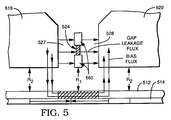
- Figure 5 represents an enlarged view of an alternative embodiment of an MR sensor that is again adapted to be placed in the head gap of a keepered media system such as that illustrated in Figure 4. Consequently, similar numerals are again used to designate similar items of the figure, with the exception that corresponding series 500 numerals are used.
- a somewhat different MR sensor is employed, but it is still mounted in the same relative position within the gap between nonmagnetic layers 527, 528.
- the sensor is bounded on either end by flux guides 560, with the lower flux guide being located at the same relative level as the bottom of the head. Consequently, the flux from the storage layer is channeled to the MR sensor by the lower flux guide, with the upper flux guide serving to balance the upper magnetic circuit.
- This embodiment offers somewhat more protection from surface defect damage than does the embodiment of Figure 3, with only a small loss of sensitivity. Also, since the MR sensor is attached to the flux guides, the full range of fabrication techniques and sensor dimensions are retained.
- the head gap has a width in the range of 2 to 15 microinches and a total height in the range of 100 to 600 microinches.
- the MR element and the SAL are designed to each have a thickness in the range of 50 to 400 Angstroms, with the MR element used in Figure 4 having a thickness near 400 Angstroms if desired.
- the isolation spacer between the MR element and the SAL should have a dimension in the range of 5 to 30 Angstroms and the outside isolation layers can be between 0.8 and 7 microinches wide.
- the MR element and the SAL can be dimensioned within the range of 40 to 240 microinches in height and the flux guide associated with the MR sensor in the embodiment of Figure 5 can have a height of about 80 microinches.
- the head is designed to accomodate a recording track width of 40 to 250 microinches, although it should be recognized that all these dimensions could vary as the technology described herein is further developed.
Landscapes
- Engineering & Computer Science (AREA)
- Manufacturing & Machinery (AREA)
- Magnetic Heads (AREA)
- Hall/Mr Elements (AREA)
- Magnetic Record Carriers (AREA)
Applications Claiming Priority (2)
| Application Number | Priority Date | Filing Date | Title |
|---|---|---|---|
| US575203 | 1990-08-30 | ||
| US57520395A | 1995-12-20 | 1995-12-20 |
Publications (2)
| Publication Number | Publication Date |
|---|---|
| EP0780833A2 true EP0780833A2 (de) | 1997-06-25 |
| EP0780833A3 EP0780833A3 (de) | 1999-01-07 |
Family
ID=24299354
Family Applications (1)
| Application Number | Title | Priority Date | Filing Date |
|---|---|---|---|
| EP96119146A Withdrawn EP0780833A3 (de) | 1995-12-20 | 1996-11-29 | Verbessertes Magnetaufzeichnungssystem mit sättigbarer Schichte und gebrauchmachend von MR-Elementen |
Country Status (4)
| Country | Link |
|---|---|
| US (1) | US5870260A (de) |
| EP (1) | EP0780833A3 (de) |
| JP (1) | JPH09288809A (de) |
| KR (1) | KR970050142A (de) |
Families Citing this family (16)
| Publication number | Priority date | Publication date | Assignee | Title |
|---|---|---|---|---|
| US5830590A (en) * | 1996-06-28 | 1998-11-03 | Ampex Corporation | Magnetic storage and reproducing system with a low permeability keeper and a self-biased magnetoresistive reproduce head |
| US6775100B1 (en) * | 1997-05-05 | 2004-08-10 | Seagate Technology Llc | Laser assisted track width definition and radial control with magnetic recording |
| JP3864637B2 (ja) | 1999-10-05 | 2007-01-10 | 富士通株式会社 | 磁気記録媒体 |
| US8397998B1 (en) | 1999-10-23 | 2013-03-19 | Ultracard, Inc. | Data storage device, apparatus and method for using same |
| US7487908B1 (en) | 1999-10-23 | 2009-02-10 | Ultracard, Inc. | Article having an embedded accessible storage member, apparatus and method for using same |
| US6816339B1 (en) * | 2000-01-10 | 2004-11-09 | Seagate Technology Llc | Perpendicular magnetic recording head with longitudinal magnetic field generator to facilitate magnetization switching |
| US6621664B1 (en) * | 2000-02-28 | 2003-09-16 | Seagate Technology Llc | Perpendicular recording head having integrated read and write portions |
| US6717770B1 (en) | 2000-03-24 | 2004-04-06 | Seagate Technology Llc | Recording head for applying a magnetic field perpendicular to the magnetizations within magnetic storage media |
| JP2001312802A (ja) * | 2000-04-26 | 2001-11-09 | Internatl Business Mach Corp <Ibm> | ディスク装置およびデータ消去方法 |
| US6493183B1 (en) * | 2000-06-29 | 2002-12-10 | International Business Machines Corporation | Thermally-assisted magnetic recording system with head having resistive heater in write gap |
| US6995950B2 (en) * | 2001-04-09 | 2006-02-07 | Maxtor Corporation | Transverse biased shields for perpendicular recording to reduce stray field sensitivity |
| US6771464B2 (en) * | 2001-10-19 | 2004-08-03 | Seagate Technology Llc | Perpendicular magnetic recording head with a laminated main write pole |
| JP2004334945A (ja) * | 2003-05-02 | 2004-11-25 | Fuji Photo Film Co Ltd | 複合型磁気ヘッド及びその製造方法 |
| US7233142B1 (en) * | 2004-09-02 | 2007-06-19 | United States Of America As Represented By The Secretary Of The Army | Planer reader of non-erasable magnetic media and local permeability |
| US7839605B2 (en) * | 2005-11-13 | 2010-11-23 | Hitachi Global Storage Technologies Netherlands B.V. | Electrical signal-processing device integrating a flux sensor with a flux generator in a magnetic circuit |
| US8048546B2 (en) * | 2009-12-16 | 2011-11-01 | Hitachi Global Storage Technologies Netherlands B.V. | Perpendicular magnetic recording disk with ordered nucleation layer and method for making the disk |
Citations (5)
| Publication number | Priority date | Publication date | Assignee | Title |
|---|---|---|---|---|
| US4657819A (en) | 1984-03-13 | 1987-04-14 | Anelva Corporation | Flexible magnetic recording medium comprising an underlying film having reduced in-plane magnetic anisotropy under a surface film having perpendicular magnetic anisotropy |
| US4717592A (en) | 1984-12-24 | 1988-01-05 | Fuji Photo Film Co., Ltd. | Vertical magnetization type recording medium and manufacturing method therefor |
| US5041922A (en) | 1985-12-13 | 1991-08-20 | Ampex Corporation | Magnetic recording medium having magnetic storage and saturable layers, and apparatus and method using the medium |
| WO1993012928A1 (en) | 1992-01-03 | 1993-07-08 | Conner Peripherals, Inc. | Magnetic recording media employing soft magnetic material |
| US9210485B2 (en) | 2005-09-26 | 2015-12-08 | Unify Gmbh & Co. Kg | Device and method for the recognition of call numbers for voice-over-IP telephony |
Family Cites Families (48)
| Publication number | Priority date | Publication date | Assignee | Title |
|---|---|---|---|---|
| GB818811A (en) * | 1954-11-26 | 1959-08-26 | Clevite Corp | Improvements in or relating to flux responsive magnetic reproducer heads |
| US3127592A (en) * | 1955-06-17 | 1964-03-31 | Frederic W Ohnstead | Static pickup head |
| US2928078A (en) * | 1956-08-16 | 1960-03-08 | Ibm | Magnetic transducer |
| GB822240A (en) * | 1957-03-29 | 1959-10-21 | Decca Record Co Ltd | Improvements in or relating to reading heads for magnetic recordings |
| US3152225A (en) * | 1958-06-11 | 1964-10-06 | Sylvania Electric Prod | Magnetic tape transducer |
| US3106617A (en) * | 1958-12-24 | 1963-10-08 | Rca Corp | Magnetic recording and reproducing head |
| US3079468A (en) * | 1958-12-24 | 1963-02-26 | Rca Corp | Magnetic recording and reproducing |
| US3188399A (en) * | 1960-11-28 | 1965-06-08 | Ampex | Magnetic transducing assembly |
| DE1144324B (de) * | 1961-09-08 | 1963-02-28 | Telefunken Patent | Vorrichtung zur magnetischen Aufzeichnung von Fernsehbild- und -tonsignalen |
| US3239823A (en) * | 1962-05-16 | 1966-03-08 | Ibm | Twin gap flux responsive head |
| US3314056A (en) * | 1962-10-02 | 1967-04-11 | Honeywell Inc | Gapless magnetic head |
| US3391254A (en) * | 1964-10-15 | 1968-07-02 | William M. Honig | Magnetic head with means for producing a shiftable high permeability region in a magnetic permeable material |
| US3432837A (en) * | 1964-12-30 | 1969-03-11 | Ibm | Sensor magnetic head with magnetic material as a gap bridge |
| US3435440A (en) * | 1965-01-04 | 1969-03-25 | Ibm | Null sweeping head |
| US3555204A (en) * | 1968-01-12 | 1971-01-12 | Ibm | Electronic sweep magnetic scanning transducer |
| GB2073472B (en) * | 1978-11-01 | 1982-12-01 | Matsushita Electric Industrial Co Ltd | Magnetic recording and reproducing apparatus |
| US4277809A (en) * | 1979-09-26 | 1981-07-07 | Memorex Corporation | Apparatus for recording magnetic impulses perpendicular to the surface of a recording medium |
| US4318136A (en) * | 1980-02-13 | 1982-03-02 | Spin Physics, Inc. | Magnetic recording apparatus and method |
| JPS5736407A (en) * | 1980-08-13 | 1982-02-27 | Toshiba Corp | Magnetic reproducer |
| JPS5758226A (en) * | 1980-09-22 | 1982-04-07 | Toshiba Corp | Magnetic recording medium |
| JPS57205813A (en) * | 1981-06-15 | 1982-12-17 | Matsushita Electric Ind Co Ltd | Magnetic head |
| CA1203898A (en) * | 1982-07-16 | 1986-04-29 | Norikazu Sawazaki | Magnetic recording and reproducing apparatus |
| JPS60121506A (ja) * | 1983-12-05 | 1985-06-29 | Tdk Corp | 磁気ヘッド |
| US4687712A (en) * | 1983-12-12 | 1987-08-18 | Matsushita Electric Industrial Co., Ltd. | Vertical magnetic recording medium |
| JPS60143431A (ja) * | 1983-12-29 | 1985-07-29 | Alps Electric Co Ltd | 垂直磁気記録媒体 |
| EP0326192A3 (de) * | 1984-02-28 | 1989-09-06 | International Business Machines Corporation | Magnetoresistive verkoppelte Dünnfilme für magnetische Flussabtastung |
| US5153796A (en) * | 1984-08-16 | 1992-10-06 | Ampex Corporation | Method and apparatus for transferring information between two magnetic bodies using a third body of magnetic material |
| US5189572A (en) * | 1984-08-16 | 1993-02-23 | Ampex Corporation | Magnetic control of a transducer signal transfer zone to effect tracking of a path along a record medium |
| US5227939A (en) * | 1984-08-16 | 1993-07-13 | Ampex Corporation | Scanning transducer having transverse information and control flux paths for reduced interference between fluxes |
| US5119255A (en) * | 1984-08-16 | 1992-06-02 | Ampex Corporation | Magnetic saturation controlled scanning magnetic transducer |
| US4782415A (en) * | 1985-10-02 | 1988-11-01 | International Business Machines Corp. | Differential twin track vertical read/write magnetic head structure |
| US4698711A (en) * | 1985-10-02 | 1987-10-06 | International Business Machines Corporation | Simplified, shielded twin-track read/write head structure |
| US4613915A (en) * | 1985-10-16 | 1986-09-23 | International Business Machines Corporation | Twin track vertical magnetic recording servo control method and apparatus with offset voltage compensation |
| US4642709A (en) * | 1985-10-16 | 1987-02-10 | International Business Machines Corporation | Twin track vertical magnetic recording servo control method |
| US4985795A (en) * | 1985-12-13 | 1991-01-15 | Ampex Corporation | Method and apparatus using a stationary magnetic body for effecting signal transfers between a moving magnetic core and a magnetic storage medium |
| JP2704957B2 (ja) * | 1985-12-13 | 1998-01-26 | アムペツクス コ−ポレ−シヨン | 個別の磁気記憶及び飽和可能な層を有する磁気記録媒体及び磁気信号処理装置ならびにこの媒体を使用する方法 |
| JP2613239B2 (ja) * | 1988-02-26 | 1997-05-21 | 株式会社日立製作所 | 磁気抵抗効果型ヘツド |
| JPH02168408A (ja) * | 1988-09-19 | 1990-06-28 | Hitachi Ltd | 記録再生用磁気ヘッドおよびその製造方法 |
| NL8802960A (nl) * | 1988-12-01 | 1990-07-02 | Philips Nv | Systeem omvattende een magneetkop en een verplaatsbare magnetische informatiedrager, alsmede een magneetkop en een magnetische informatiedrager geschikt voor toepassing in het systeem. |
| JPH02162502A (ja) * | 1988-12-16 | 1990-06-22 | Matsushita Electric Ind Co Ltd | ディジタル信号記録装置 |
| US5130876A (en) * | 1989-12-08 | 1992-07-14 | Ampex Corporation | Solid state scanning transducer that utilizes low flux densities |
| JPH04102215A (ja) * | 1990-08-21 | 1992-04-03 | Sony Corp | 磁気ヘッド |
| DE69126082T2 (de) * | 1990-09-27 | 1997-10-02 | Toshiba Kawasaki Kk | Magnetischer Kopf |
| JP3411626B2 (ja) * | 1992-08-27 | 2003-06-03 | ティーディーケイ株式会社 | 磁性多層膜および磁気抵抗効果素子ならびにそれらの製造方法 |
| JP3083218B2 (ja) * | 1993-03-17 | 2000-09-04 | 富士通株式会社 | 薄膜磁気ヘッド |
| US5966272A (en) * | 1993-06-21 | 1999-10-12 | Read-Rite Corporation | Magnetoresistive read head having an exchange layer |
| JP2683503B2 (ja) * | 1993-09-02 | 1997-12-03 | インターナショナル・ビジネス・マシーンズ・コーポレイション | 磁性膜構造 |
| US5436779A (en) * | 1994-03-31 | 1995-07-25 | Read-Rite Corporation | Integrated yoke magnetoresistive transducer with magnetic shunt |
-
1996
- 1996-11-29 EP EP96119146A patent/EP0780833A3/de not_active Withdrawn
- 1996-12-12 KR KR1019960064837A patent/KR970050142A/ko not_active Withdrawn
- 1996-12-20 JP JP8342159A patent/JPH09288809A/ja active Pending
-
1997
- 1997-05-23 US US08/862,415 patent/US5870260A/en not_active Expired - Fee Related
Patent Citations (5)
| Publication number | Priority date | Publication date | Assignee | Title |
|---|---|---|---|---|
| US4657819A (en) | 1984-03-13 | 1987-04-14 | Anelva Corporation | Flexible magnetic recording medium comprising an underlying film having reduced in-plane magnetic anisotropy under a surface film having perpendicular magnetic anisotropy |
| US4717592A (en) | 1984-12-24 | 1988-01-05 | Fuji Photo Film Co., Ltd. | Vertical magnetization type recording medium and manufacturing method therefor |
| US5041922A (en) | 1985-12-13 | 1991-08-20 | Ampex Corporation | Magnetic recording medium having magnetic storage and saturable layers, and apparatus and method using the medium |
| WO1993012928A1 (en) | 1992-01-03 | 1993-07-08 | Conner Peripherals, Inc. | Magnetic recording media employing soft magnetic material |
| US9210485B2 (en) | 2005-09-26 | 2015-12-08 | Unify Gmbh & Co. Kg | Device and method for the recognition of call numbers for voice-over-IP telephony |
Also Published As
| Publication number | Publication date |
|---|---|
| EP0780833A3 (de) | 1999-01-07 |
| US5870260A (en) | 1999-02-09 |
| JPH09288809A (ja) | 1997-11-04 |
| KR970050142A (ko) | 1997-07-29 |
Similar Documents
| Publication | Publication Date | Title |
|---|---|---|
| US6043947A (en) | Magnetic storage and reproducing system with a low permeability keeper and a self-biased magnetoresitive reproduce head | |
| US5434826A (en) | Multilayer hard bias films for longitudinal biasing in magnetoresistive transducer | |
| US5311387A (en) | Three-pole magnetic recording head with high readback resolution | |
| US5901018A (en) | Magnetic tunnel junction magnetoresistive read head with sensing layer as rear flux guide | |
| KR100259429B1 (ko) | 강화된 자기저항을 갖는 스핀 밸브 센서 | |
| US5870260A (en) | Magnetic recording system having a saturable layer and detection using MR element | |
| US5111352A (en) | Three-pole magnetic head with reduced flux leakage | |
| US5838521A (en) | Magnetoresistive transducer having laminated magnetic shields | |
| US5434733A (en) | Planar head having separate read and write gaps | |
| US5880912A (en) | Magnetic head with biased GMR element and sense current compensation | |
| JPH0845037A (ja) | 薄膜磁気抵抗トランスジューサ | |
| US4255772A (en) | Read/write magnetic head assembly with magnetoresistive sensor | |
| US20030117749A1 (en) | Perpendicular read/write head for use in a disc drive storage system | |
| US5909344A (en) | Magnetoresistive sensor with high resistivity flux guide | |
| US5722157A (en) | Method of making an induction and magnetoresistance type composite magnetic head | |
| Muraoka et al. | Low inductance and high efficiency single-pole writing head for perpendicular double layer recording media | |
| US5742457A (en) | Horizontal shared-pole magnetic read/write head having polarization conductor disabling write pole | |
| US5926350A (en) | Dual gap horizontal thin film inductive head | |
| US5600518A (en) | Magnetoresistive head having a stepped magnetoresistive film element | |
| JPH11175925A (ja) | 磁気抵抗効果型素子及び磁気記録再生装置 | |
| JP3184430B2 (ja) | 磁気媒体に対する記録・再生装置 | |
| JP2002008209A (ja) | 複合型薄膜磁気ヘッド | |
| Dee | Read heads for magnetic tapes | |
| JP2002245607A (ja) | 磁気抵抗効果型ヘッド | |
| Takano et al. | Contact magnetoresistive head for perpendicular magnetic recording |
Legal Events
| Date | Code | Title | Description |
|---|---|---|---|
| PUAI | Public reference made under article 153(3) epc to a published international application that has entered the european phase |
Free format text: ORIGINAL CODE: 0009012 |
|
| AK | Designated contracting states |
Kind code of ref document: A2 Designated state(s): AT DE FR GB |
|
| PUAL | Search report despatched |
Free format text: ORIGINAL CODE: 0009013 |
|
| AK | Designated contracting states |
Kind code of ref document: A3 Designated state(s): AT DE FR GB |
|
| 17P | Request for examination filed |
Effective date: 19990129 |
|
| 17Q | First examination report despatched |
Effective date: 20011218 |
|
| STAA | Information on the status of an ep patent application or granted ep patent |
Free format text: STATUS: THE APPLICATION IS DEEMED TO BE WITHDRAWN |
|
| 18D | Application deemed to be withdrawn |
Effective date: 20020629 |