EP0780754B1 - Drehknopf mit zwei Betätigungsfunktionen - Google Patents
Drehknopf mit zwei Betätigungsfunktionen Download PDFInfo
- Publication number
- EP0780754B1 EP0780754B1 EP96119582A EP96119582A EP0780754B1 EP 0780754 B1 EP0780754 B1 EP 0780754B1 EP 96119582 A EP96119582 A EP 96119582A EP 96119582 A EP96119582 A EP 96119582A EP 0780754 B1 EP0780754 B1 EP 0780754B1
- Authority
- EP
- European Patent Office
- Prior art keywords
- rotary knob
- contact
- circuit board
- contact disk
- printed circuit
- Prior art date
- Legal status (The legal status is an assumption and is not a legal conclusion. Google has not performed a legal analysis and makes no representation as to the accuracy of the status listed.)
- Expired - Lifetime
Links
- 230000006870 function Effects 0.000 title claims description 31
- 239000004020 conductor Substances 0.000 claims description 26
- 238000010411 cooking Methods 0.000 claims description 6
- 230000000630 rising effect Effects 0.000 claims 1
- 238000010586 diagram Methods 0.000 description 2
- 230000006835 compression Effects 0.000 description 1
- 238000007906 compression Methods 0.000 description 1
- 238000011161 development Methods 0.000 description 1
- 230000018109 developmental process Effects 0.000 description 1
- 238000002347 injection Methods 0.000 description 1
- 239000007924 injection Substances 0.000 description 1
- 230000001105 regulatory effect Effects 0.000 description 1
- 230000011218 segmentation Effects 0.000 description 1
- 239000000243 solution Substances 0.000 description 1
- 238000011144 upstream manufacturing Methods 0.000 description 1
Images

Classifications
-
- G—PHYSICS
- G05—CONTROLLING; REGULATING
- G05G—CONTROL DEVICES OR SYSTEMS INSOFAR AS CHARACTERISED BY MECHANICAL FEATURES ONLY
- G05G13/00—Manually-actuated control mechanisms provided with two or more controlling members and also two or more controlled members
- G05G13/02—Manually-actuated control mechanisms provided with two or more controlling members and also two or more controlled members with separate controlling members for preselection and shifting of controlled members
-
- G—PHYSICS
- G04—HOROLOGY
- G04C—ELECTROMECHANICAL CLOCKS OR WATCHES
- G04C3/00—Electromechanical clocks or watches independent of other time-pieces and in which the movement is maintained by electric means
- G04C3/001—Electromechanical switches for setting or display
- G04C3/005—Multiple switches
-
- H—ELECTRICITY
- H01—ELECTRIC ELEMENTS
- H01H—ELECTRIC SWITCHES; RELAYS; SELECTORS; EMERGENCY PROTECTIVE DEVICES
- H01H25/00—Switches with compound movement of handle or other operating part
- H01H25/06—Operating part movable both angularly and rectilinearly, the rectilinear movement being along the axis of angular movement
Definitions
- the invention relates to a rotary knob with two actuating functions Turning and pressing according to the preamble of claim 1.
- Such an operation is such. B. that of an operating mode selector switch.
- knobs are known, for. B. in car radios where the volume is regulated by turning a rotary knob, whereas by Pressing the rotary button starts a station search.
- EP 0 050 208 A1 discloses a generic rotary knob in which various functions can be selected by turning them into defined positions.
- the rotary knob has an axis of rotation mounted on a printed circuit board with conductor tracks and two rigid contact levers which can be rotated about this axis of rotation and which are connected to the Interconnect conductor tracks on the circuit board.
- By selecting one of the Functions by turning the rotary knob becomes immediate and simultaneous an adjustment function z. B. on a device with a time display by automatic Generating pulses executed.
- the counting direction of this adjustment function can be reversed by pressing the push button.
- From DE 31 32 731 A1 is a rotary knob with two actuating functions Known turning and pushing, whereby by turning into defined positions different Functions can be preselected and when pressed in the selected position an electrical contact is closed.
- the basic idea of the invention is with a rotary knob in its Normal position by turning into several defined positions, multiple functions on a device, especially a stove timer.
- the rotary knob In the selected Position, the rotary knob can be pressed and releases an adjustment function there by generating pulses for the selected function.
- a corresponding adjustment to a time display In this way are a cooking time on a stove timer in addition to the time of day setting End of cooking time or start of cooking time and a short time can be set. All of these Common to functions is that they require a time setting.
- the Adjustment function z. B. makes a temperature setting. It is important that at the adjustment function the size of the adjustment is visible on the display.
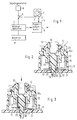
- a knob (1) is shown, which Outputs (2) and (3).
- the output (3) is connected to a switch (5), which can connect a pulse generator (6) to a display memory (7).
- the latter is upstream of a display, digital or analog.
- the knob (1) is according to Figure 2 with its housing (10) on a circuit board (11) stored.
- a displaceably mounted switch axis is located in the housing (10) (12) provided against the force of a spring (13) in the drawing down is movable.
- a bore (14) the shaft of the operating button - not shown - be stored.
- the switch axis (12) is prevented from falling out by a resilient part (10a) the circuit board (11) secured.
- a safety hook on the switch axis (12) (15) provided which - in the preassembled state, i.e. H. before snapping in the printed circuit board - a contact plate (17) at which it is pressed out the spring (13) prevents.
- a rib (16) is also injection molded onto the switch axis (12), which serves to deflect the contact disk (17). This contact disc (17) is secured against rotation on the switch axis (12), but can be tilted.
- a detent (23) is provided on the switch axis (12), which with a spring-formed part (10a) of the housing (10) cooperates.
- the circuit board (11) with the conductor tracks (20, 21 and 23) is shown
- the actually opaque contact disk (17) is the better one in FIG Recognizable because of transparent, to look at the one below it free conductor tracks and the corresponding contacts.
- the contact disc (17) lies with its contact (18) on the innermost conductor track (20).
- the conductor track pieces (23) are from a contact (24) when turning the Painted contact disc (17).
- This contact (24) is in Figures 2 and 3, because it lies behind the switch axis (12), not recognizable.
- the conductor track (20) is the central conductor track connected to a pole of the power source, the Conductor (23) serves, due to its segmentation, for the selection of the functions, d. h Each of these segments is assigned to a different function of the device.
- the conductor track (21) is assigned to the adjustment function and triggers indifferently wherever the contact (19) comes to rest on this conductor path, always the same impulse from the pulse generator (6).
Landscapes
- Physics & Mathematics (AREA)
- General Physics & Mathematics (AREA)
- Engineering & Computer Science (AREA)
- Automation & Control Theory (AREA)
- Rotary Switch, Piano Key Switch, And Lever Switch (AREA)
- Switches With Compound Operations (AREA)
Description
- Figur 1
- ein Blockschaltbild zur Funktionsweise des Drehknopfs in einem Gerät;
- Figur 2
- einen Schnitt durch den Drehknopf in Normalposition entlang der Linie II - II (Fig. 4);
- Figur 3
- einen Schnitt gleich Fig. 2 durch den Drehknopf in gedrückter Position;
- Figur 4
- eine Draufsicht auf die Leiterbahnen mit durchsichtig dargestellter Kontaktscheibe.
Claims (7)
- Drehknopf mit zwei Betätigungsfunktionen durch Drehen und Drücken, wobei durch Verdrehen in definierte Stellungen verschiedene Funktionen auswählbar sind und bei Drücken in der ausgewählten Stellung eine Verstellfunktion an einem Gerät mit einer Zeitanzeige durch automatisches Erzeugen von Impulsen ausgeführt wird und wobei der Drehknopf (1) eine auf einer Leiterplatte (11) mit kreisförmigen, konzentrisch angeordneten Leiterbahnen (20, 21, 23) gelagerte Drehachse (12) und eine Kontaktscheibe (17) mit Kontakten (18, 24, 19), die mit den Leiterbahnen auf der Leiterplatte zusammenwirken, aufweist, wobei die Kontaktscheibe (17) verdrehsicher auf der Drehachse (12) gelagert ist,
dadurch gekennzeichnet,daß die Kontaktscheibe (17) auch kippbar auf der Drehachse (12) gelagert ist und in den beiden Kippstellungen, z.B. gekippt oder nicht gekippt, mit unterschiedlichen Leiterbahnen (20, 21, 23) zusammenwirkt unddaß die Leiterplatte (11) wenigstens drei Leiterbahnen (20, 21, 23) und die Kontaktscheibe (17) wenigstens drei Kontakte (18, 24, 19) aufweist. - Drehknopf nach Anspruch 1,
dadurch gekennzeichnet,
daß der Drehknopf (1) in einer Herdschaltuhr Anwendung findet und mehrere an der Zeitanzeige (8) darstellbare Funktionen wie z. B. Zeit, Kochdauer und/oder Kochzeitanfang und/oder Kochzeitende beinhaltet und bei der Verstellung die Einstellung der gewünschten Zeit für diese Funktion vorgenommen wird. - Drehknopf nach Anspruch 1 oder 2,
dadurch gekennzeichnet,
daß von den wenigstens drei auf der Leiterplatte (11) vorgesehenen kreisförmigen, konzentrisch angeordneten Leiterbahnen (20, 21, 23) die innerste (20) mit einem gemeinsamen Pol der Spannungsquelle verbunden ist, die mittlere (23) aus mehreren einzelnen Bahnsegmenten, jedes einer Funktion zugeordnet, besteht und die äußerste (21) der Verstellfunktion zugeordnet ist und sich über einen Teilbereich des kreisförmigen Umfangs erstreckt. - Drehknopf nach Anspruch 1, 2 oder 3,
dadurch gekennzeichnet,
daß die Kontaktscheibe (17) rund und durchgängig leitend ist. - Drehknopf nach Anspruch 4,
dadurch gekennzeichnet,
daß ein dem Kontakt (19) für die äußerste Leiterbahn (21) auf der abgewandten Seite der Drehachse (12) ein Abstützkontakt (22) gegenüberliegt, der bei nicht gekippter Kontaktscheibe (17) die Kontakte auf der inneren (20) und der mittleren (23) Leiterbahn hält. - Drehknopf nach Anspruch 4,
dadurch gekennzeichnet,
daß die gegen Federkraft (13) gekippte Kontaktscheibe (17) den äußersten Kontakt (19) mit der äußersten Leiterbahn (21) zusätzlich in elektrische Verbindung bringt, wobei der Abstützkontakt (22) von seiner Auflage auf der Leiterplatte (11), vorzugsweise der inneren Leiterbahn (20) abhebt. - Drehknopf nach Anspruch 1, 2 oder 6,
dadurch gekennzeichnet,
daß auf seiner Drehachse (12) eine Rippe (16) angeordnet ist, welche in der Position des Drehknopfes "Verstellen" gegen Federkraft auf die Kontaktscheibe (17) einseitig drückt diese kippt.
Applications Claiming Priority (3)
| Application Number | Priority Date | Filing Date | Title |
|---|---|---|---|
| DE19547343A DE19547343A1 (de) | 1995-12-19 | 1995-12-19 | Drehknopf mit zwei Betätigungsfunktionen |
| DE19547343 | 1995-12-19 | ||
| DE29520079U DE29520079U1 (de) | 1995-12-19 | 1995-12-19 | Drehknopf mit zwei Betätigungsfunktionen |
Publications (2)
| Publication Number | Publication Date |
|---|---|
| EP0780754A1 EP0780754A1 (de) | 1997-06-25 |
| EP0780754B1 true EP0780754B1 (de) | 2000-03-22 |
Family
ID=29737652
Family Applications (1)
| Application Number | Title | Priority Date | Filing Date |
|---|---|---|---|
| EP96119582A Expired - Lifetime EP0780754B1 (de) | 1995-12-19 | 1996-12-06 | Drehknopf mit zwei Betätigungsfunktionen |
Country Status (2)
| Country | Link |
|---|---|
| EP (1) | EP0780754B1 (de) |
| DE (3) | DE29520079U1 (de) |
Families Citing this family (11)
| Publication number | Priority date | Publication date | Assignee | Title |
|---|---|---|---|---|
| DE29712121U1 (de) | 1997-07-10 | 1997-09-11 | Sigma Laborzentrifugen Gmbh, 37520 Osterode | Steuerungseinrichtung für eine Laborzentrifuge |
| DE19840060B4 (de) * | 1998-09-03 | 2004-06-24 | Hella Kg Hueck & Co. | Dreh-Druck-Schalter für eine Fahrzeugkomponente, insbesondere für eine Fahrzeuginnenraum-Heizungs- oder Klimaanlage |
| FR2785385B1 (fr) * | 1998-10-29 | 2001-01-19 | Valeo Electronique | Dispositif d'encodage incremental avec une fonction poussoir |
| DE10008015A1 (de) * | 2000-02-22 | 2001-08-23 | Bsh Bosch Siemens Hausgeraete | Haushaltsgerät mit einer Zeitschaltereinrichtung |
| DE10107363B4 (de) * | 2001-02-12 | 2009-02-12 | Trw Automotive Electronics & Components Gmbh & Co. Kg | Elektrischer Dreh/Zug-Schalter |
| US6803531B2 (en) | 2001-02-12 | 2004-10-12 | Trw Automotive Electronics & Components Gmbh & Co. Kg | Electrical switch for vehicle lighting |
| DE10163194A1 (de) * | 2001-12-21 | 2003-07-03 | Bsh Bosch Siemens Hausgeraete | Elektromechanische Stufenschaltvorrichtung mit zeitgesteuerten Zusatzfunktionen |
| FR2845198B1 (fr) * | 2002-09-27 | 2005-05-06 | Dav | Commutateur electrique a actionnement lineaire et rotatif |
| ITMO20070257A1 (it) * | 2007-07-31 | 2009-02-01 | Robopac Sa | Dispositivo di controllo |
| DE202011108755U1 (de) | 2011-11-30 | 2012-02-01 | Peter Moser | Drehknopf für einen Regler mit Einknopfbedienung für ein Lüftungssystem |
| CN208889254U (zh) | 2018-11-05 | 2019-05-21 | 京东方科技集团股份有限公司 | 显示装置 |
Family Cites Families (10)
| Publication number | Priority date | Publication date | Assignee | Title |
|---|---|---|---|---|
| DE8027773U1 (de) * | 1980-10-17 | 1985-08-14 | Bosch-Siemens Hausgeräte GmbH, 7000 Stuttgart | Anordnung zur Eingabe von Einstellwerten an elektronische Schaltungsanordnungen |
| DE3129802A1 (de) * | 1981-07-29 | 1983-02-17 | Licentia Patent-Verwaltungs-Gmbh, 6000 Frankfurt | Steuereinrichtung zur digitalen einstellung von funktionen und zugeordneten datenwerten |
| DE3132731A1 (de) * | 1981-08-19 | 1983-03-03 | Licentia Patent-Verwaltungs-Gmbh, 6000 Frankfurt | Schalter zum verbinden zweier elektrischer anschluesse |
| DE3235994C2 (de) * | 1982-09-29 | 1986-08-07 | Wieland 8501 Eckental Bartel | Stellvorrichtung für zwei Funktionen |
| DE8700718U1 (de) * | 1987-01-16 | 1987-03-05 | Imperial-Werke GmbH, 32257 Bünde | Schalter für einen beheizbaren Back- oder Bratofen |
| DE8804316U1 (de) * | 1988-03-30 | 1988-06-01 | Hechinger, Helmut, 7730 Villingen-Schwenningen | Codierschalter |
| DE3821004A1 (de) * | 1988-06-22 | 1989-12-28 | Thomson Brandt Gmbh | Drehbetaetigter geber fuer digitale impulse und anwendungsverfahren fuer diesen |
| US5134262A (en) * | 1989-05-31 | 1992-07-28 | Goldstar Co., Ltd. | Function control unit with timer for microwave oven |
| EP0414941B1 (de) * | 1989-08-30 | 1993-07-28 | Siemens Aktiengesellschaft | Stellantrieb |
| GB2267554B (en) * | 1992-06-01 | 1995-08-02 | Matsushita Electric Industrial Co Ltd | Heating apparatus |
-
1995
- 1995-12-19 DE DE29520079U patent/DE29520079U1/de not_active Expired - Lifetime
- 1995-12-19 DE DE19547343A patent/DE19547343A1/de not_active Withdrawn
-
1996
- 1996-12-06 EP EP96119582A patent/EP0780754B1/de not_active Expired - Lifetime
- 1996-12-06 DE DE59604764T patent/DE59604764D1/de not_active Expired - Fee Related
Also Published As
| Publication number | Publication date |
|---|---|
| DE19547343A1 (de) | 1997-06-26 |
| DE59604764D1 (de) | 2000-04-27 |
| DE29520079U1 (de) | 1997-04-17 |
| EP0780754A1 (de) | 1997-06-25 |
Similar Documents
| Publication | Publication Date | Title |
|---|---|---|
| DE69408418T2 (de) | Hebelschaltervorrichtung, Verfahren zur Steuerung von Schaltern in solcher Vorrichtung und Verfahren zum Ausgeben von Datensignalen | |
| EP0234193A2 (de) | Schalteranordnung | |
| DE2623384A1 (de) | Tastenschalter | |
| DE4109033C2 (de) | Drucktastenmechanismus | |
| DE4215097C2 (de) | Schalteranordnung | |
| EP0780754A1 (de) | Drehknopf mit zwei Betätigungsfunktionen | |
| DE3613702C2 (de) | ||
| DE3129210C2 (de) | Elektrische Schaltvorrichtung | |
| EP0592925B1 (de) | Handgefahrenmelder | |
| DE2231966C3 (de) | Drucktastenschalter mit mechanischer Schaltstellungsanzeige | |
| DE2933150C2 (de) | Tastenfeld | |
| DE102020133479B3 (de) | Elektrisches/elektronisches Installationsgerät | |
| DE19621192A1 (de) | Niederspannungsschaltgerät | |
| DE2732723C2 (de) | Elektrische Schaltvorrichtung | |
| DE1911104C3 (de) | Elektrischer Schnappschalter | |
| WO2000010185A1 (de) | Bedienelement zum selektiven herstellen elektrischer kontakte | |
| DE3604724C2 (de) | ||
| DE3114563C2 (de) | Drucktastenschalter | |
| DE2953881C1 (de) | Tastenfeld | |
| DE7520309U (de) | Schalter mit zwei Schaltstellungen | |
| EP1004156B1 (de) | Elektrisches gerät | |
| DE29508432U1 (de) | Elektrischer Taster | |
| DE102024112348A1 (de) | Betätigungsbaugruppe und Küchengerät | |
| EP0825499A2 (de) | Vorrichtung für elektromechanische Schaltuhren | |
| DE102004047504B3 (de) | Folientastschalter |
Legal Events
| Date | Code | Title | Description |
|---|---|---|---|
| PUAI | Public reference made under article 153(3) epc to a published international application that has entered the european phase |
Free format text: ORIGINAL CODE: 0009012 |
|
| 17P | Request for examination filed |
Effective date: 19970422 |
|
| AK | Designated contracting states |
Kind code of ref document: A1 Designated state(s): CH DE ES FR GB IT LI |
|
| RAP1 | Party data changed (applicant data changed or rights of an application transferred) |
Owner name: DIEHL STIFTUNG & CO. |
|
| 17Q | First examination report despatched |
Effective date: 19981203 |
|
| GRAG | Despatch of communication of intention to grant |
Free format text: ORIGINAL CODE: EPIDOS AGRA |
|
| GRAG | Despatch of communication of intention to grant |
Free format text: ORIGINAL CODE: EPIDOS AGRA |
|
| GRAH | Despatch of communication of intention to grant a patent |
Free format text: ORIGINAL CODE: EPIDOS IGRA |
|
| GRAH | Despatch of communication of intention to grant a patent |
Free format text: ORIGINAL CODE: EPIDOS IGRA |
|
| GRAA | (expected) grant |
Free format text: ORIGINAL CODE: 0009210 |
|
| AK | Designated contracting states |
Kind code of ref document: B1 Designated state(s): CH DE ES FR GB IT LI |
|
| PG25 | Lapsed in a contracting state [announced via postgrant information from national office to epo] |
Ref country code: IT Free format text: LAPSE BECAUSE OF FAILURE TO SUBMIT A TRANSLATION OF THE DESCRIPTION OR TO PAY THE FEE WITHIN THE PRE;WARNING: LAPSES OF ITALIAN PATENTS WITH EFFECTIVE DATE BEFORE 2007 MAY HAVE OCCURRED AT ANY TIME BEFORE 2007. THE CORRECT EFFECTIVE DATE MAY BE DIFFERENT FROM THE ONE RECORDED.SCRIBED TIME-LIMIT Effective date: 20000322 Ref country code: GB Free format text: LAPSE BECAUSE OF FAILURE TO SUBMIT A TRANSLATION OF THE DESCRIPTION OR TO PAY THE FEE WITHIN THE PRESCRIBED TIME-LIMIT Effective date: 20000322 Ref country code: ES Free format text: THE PATENT HAS BEEN ANNULLED BY A DECISION OF A NATIONAL AUTHORITY Effective date: 20000322 |
|
| REG | Reference to a national code |
Ref country code: CH Ref legal event code: EP |
|
| REF | Corresponds to: |
Ref document number: 59604764 Country of ref document: DE Date of ref document: 20000427 |
|
| REG | Reference to a national code |
Ref country code: CH Ref legal event code: NV Representative=s name: A. BRAUN, BRAUN, HERITIER, ESCHMANN AG PATENTANWAE |
|
| ET | Fr: translation filed | ||
| GBV | Gb: ep patent (uk) treated as always having been void in accordance with gb section 77(7)/1977 [no translation filed] |
Effective date: 20000322 |
|
| PLBE | No opposition filed within time limit |
Free format text: ORIGINAL CODE: 0009261 |
|
| STAA | Information on the status of an ep patent application or granted ep patent |
Free format text: STATUS: NO OPPOSITION FILED WITHIN TIME LIMIT |
|
| 26N | No opposition filed | ||
| PGFP | Annual fee paid to national office [announced via postgrant information from national office to epo] |
Ref country code: FR Payment date: 20011029 Year of fee payment: 6 |
|
| PGFP | Annual fee paid to national office [announced via postgrant information from national office to epo] |
Ref country code: CH Payment date: 20011213 Year of fee payment: 6 |
|
| PG25 | Lapsed in a contracting state [announced via postgrant information from national office to epo] |
Ref country code: LI Free format text: LAPSE BECAUSE OF NON-PAYMENT OF DUE FEES Effective date: 20021231 Ref country code: CH Free format text: LAPSE BECAUSE OF NON-PAYMENT OF DUE FEES Effective date: 20021231 |
|
| REG | Reference to a national code |
Ref country code: CH Ref legal event code: PL |
|
| PG25 | Lapsed in a contracting state [announced via postgrant information from national office to epo] |
Ref country code: FR Free format text: LAPSE BECAUSE OF NON-PAYMENT OF DUE FEES Effective date: 20030901 |
|
| REG | Reference to a national code |
Ref country code: FR Ref legal event code: ST |
|
| PGFP | Annual fee paid to national office [announced via postgrant information from national office to epo] |
Ref country code: DE Payment date: 20060221 Year of fee payment: 10 |
|
| PG25 | Lapsed in a contracting state [announced via postgrant information from national office to epo] |
Ref country code: DE Free format text: LAPSE BECAUSE OF NON-PAYMENT OF DUE FEES Effective date: 20070703 |