EP0780631A2 - Method and burner for combustion of hydrogen - Google Patents
Method and burner for combustion of hydrogen Download PDFInfo
- Publication number
- EP0780631A2 EP0780631A2 EP96119733A EP96119733A EP0780631A2 EP 0780631 A2 EP0780631 A2 EP 0780631A2 EP 96119733 A EP96119733 A EP 96119733A EP 96119733 A EP96119733 A EP 96119733A EP 0780631 A2 EP0780631 A2 EP 0780631A2
- Authority
- EP
- European Patent Office
- Prior art keywords
- burner
- hydrogen
- air
- burner according
- combustion
- Prior art date
- Legal status (The legal status is an assumption and is not a legal conclusion. Google has not performed a legal analysis and makes no representation as to the accuracy of the status listed.)
- Granted
Links
Images


Classifications
-
- F—MECHANICAL ENGINEERING; LIGHTING; HEATING; WEAPONS; BLASTING
- F23—COMBUSTION APPARATUS; COMBUSTION PROCESSES
- F23D—BURNERS
- F23D14/00—Burners for combustion of a gas, e.g. of a gas stored under pressure as a liquid
- F23D14/46—Details, e.g. noise reduction means
- F23D14/70—Baffles or like flow-disturbing devices
-
- F—MECHANICAL ENGINEERING; LIGHTING; HEATING; WEAPONS; BLASTING
- F23—COMBUSTION APPARATUS; COMBUSTION PROCESSES
- F23D—BURNERS
- F23D14/00—Burners for combustion of a gas, e.g. of a gas stored under pressure as a liquid
- F23D14/20—Non-premix gas burners, i.e. in which gaseous fuel is mixed with combustion air on arrival at the combustion zone
-
- F—MECHANICAL ENGINEERING; LIGHTING; HEATING; WEAPONS; BLASTING
- F23—COMBUSTION APPARATUS; COMBUSTION PROCESSES
- F23C—METHODS OR APPARATUS FOR COMBUSTION USING FLUID FUEL OR SOLID FUEL SUSPENDED IN A CARRIER GAS OR AIR
- F23C2900/00—Special features of, or arrangements for combustion apparatus using fluid fuels or solid fuels suspended in air; Combustion processes therefor
- F23C2900/9901—Combustion process using hydrogen, hydrogen peroxide water or brown gas as fuel
-
- F—MECHANICAL ENGINEERING; LIGHTING; HEATING; WEAPONS; BLASTING
- F23—COMBUSTION APPARATUS; COMBUSTION PROCESSES
- F23D—BURNERS
- F23D2209/00—Safety arrangements
- F23D2209/20—Flame lift-off / stability
Definitions
- the invention relates to a method for burning hydrogen and a burner for carrying out the method.
- NOx nitrogen oxide
- a distribution chamber of plate-like shape for the hydrogen is inserted transversely to the flow direction of the air, hereinafter referred to as the main flow direction, into a combustion chamber, the distribution chamber being penetrated in the main flow direction by a multiplicity of air guide tubes with an inlet opening and an outlet opening.
- Each air duct is connected to the distribution chamber via small bores, which are arranged near the inlet opening.
- the invention has for its object to provide a method for diffusion combustion of H2 and a burner for performing this method so that a drastic increase in the combustion zones, a significant reduction in NOx formation compared to previous burners with diffusion combustion is achieved.
- An advantage of the embodiment according to claim 2 is that the hydrogen exerts a particularly good cooling effect on the structure.
- Fin. 1 to 4 show a burner for burning H2 for installation, for example, in the combustion chamber of a gas turbine.
- the burner has a plate-like shape and is installed transversely to the main flow direction in the combustion chamber.
- the edge area of the burner and its connection to the combustion chamber housing, not shown, is not shown and can be of any design.
- the burner consists of a first perforated plate 2 and a second perforated plate 3, which are kept at a constant distance d by a plurality of guide tubes 4.
- the holes can be arranged according to certain matrix patterns.
- the first perforated plate 2 consists for example of a suitable metal and is impermeable to gas.
- the second perforated plate 3 is gas-permeable and consists of a suitable porous material, for example of a sintered metal.
- the holes in the two plates 2, 3 are congruent so that each hole in the first plate 2 forms a pair of holes with the associated hole in the second plate 3.
- the burner is held together essentially by inserting and fixing a guide tube 4 as a spacer in each pair of holes.
- the guide tubes 4 have peripheral beads 5 which are rolled outwards.
- the guide tubes 4 are fixed in the perforated plate 2, for example, by soldering or welding, whereas the fixing in the plate 3 can be carried out, for example, by rolling or flanging.
- each guide tube 4 an air guide pin 6 is used, as shown in FIGS. 3 and 4 is shown enlarged.
- the guide pin basically consists of a cylindrical rotating body with a stop 6a, a guide part 6b, a holder 8 and a disk 9.
- the outer diameter of the guide part 6b corresponds approximately to the inner diameter of the guide tube 4 and has four axial guide channels 7 in the example embodiment shown .
- the holder 8 is attached to the guide part on the right in FIG.
- the stop 6a is formed by a region which is short in the axial direction and whose outer diameter is larger than that of the guide part 6b.
- a guide pin 6 is inserted into each guide tube 4 from the air side of the burner until the stop 6a abuts the perforated plate 2 and is permanently fixed in this position.
- Such an assembly forms an injector.
- gaseous hydrogen is introduced into the distribution chamber between the perforated plates 2, 3. Air is also blown into the combustion chamber through the guide tubes.
- the hydrogen flows within the distribution chamber transversely to the main flow direction and is distributed in a fine distribution to the local areas of the porous perforated plate 3, through which it enters the combustion chamber and forms a hydrogen environment here.
- an air flow in the manner of a cone jacket arises as a result of the deflection through the disk 9, which enters a process of forming a mixture with the surrounding hydrogen and thereby forms a rotationally symmetrical diffusion flame.
- the interaction of each other is more conducive to the activation of the mixing process adjacent cone flames.
- the geometry of the guide bolts 6 is selected so that when they are inserted up to the respective stop 6a, a predetermined deflection, ie a predetermined flame shape, results.
- the stops 6a are omitted for reasons of weight.
- the guide pins 6 are inserted into the guide tubes 4 in a predetermined axial position by means of a manufacturing device. Due to the extremely simple construction of the injectors, they can be miniaturized in such a way that a much larger number of them can be installed per combustion chamber. As a result of the miniaturization in the order of magnitude specified, the burning zones designed according to the invention are called micro-burning zones.
- the figures 6 and 7 show a further embodiment of a burner according to the invention, consisting of individual elongated distributor channels 11 of U-shaped cross section which are provided for the hydrogen and which are closed off from the combustion chamber by walls 12 made of a porous sintered metal.
- the channels 11 are connected to one another by perforated profiles 13 of angular cross section in such a way that the free longitudinal edges of a perforated profile 13 are fastened to the longitudinal edges of two adjacent distributor channels 11.
- the holes 14 are made in the strip-shaped legs of the perforated profiles 13 at a uniform distance.
- gaseous hydrogen is introduced into the distribution channels 11.
- air is blown into the combustion chamber through the bores 14.
- the hydrogen flows within the distribution channels 11 transversely to the main flow direction and is distributed through a fine distribution to the local areas of the porous walls 12, through which it enters the combustion chamber and forms a hydrogen environment here.
- a stoichiometric zone forms in the region of each bore 14, which zone is ignited when the Brenners forms its own flame.
- This burner is particularly simple and can be manufactured as a sheet metal construction. One can proceed, for example, in such a way that the U-shaped distribution channels 11 are bent from sheet metal, each U-leg being connected in one piece with an obliquely angled perforated strip. After the porous walls 12 have been inserted, adjacent channels 11 are connected to one another, for example by welding along the free edges of the perforated strips.
- This burner can be miniaturized in such a way that several thousand combustion zones can be reached within one combustion chamber.
- the H2 is distributed over the distribution chamber or via the distribution channels to thousands of micro-combustion zones, so that, as it were, microdiffusion combustion of the hydrogen takes place.
- the main advantage of this inverse hydrogen diffusion combustion is that the structure is cooled well by the H2.
- porous metallic materials can also be used instead of the porous sintered metals.
- Porous materials based on metallic fibers such as are known, for example, under the name "felt metal" are also suitable.
- the porous material consists of a ceramic material.
- a perforated plate with a defined fine hole pattern can be placed upstream of a relatively thin layer of porous material or used alone.
- the figures 8 to 11 show a further embodiment of a burner which, in contrast to the previous ones, does not work with inverse but with regular diffusion combustion.
- This burner again consists essentially of two congruent perforated plates, which are designated 15 and 16 here.
- the two perforated plates are firmly connected to one another via guide tubes 17, each having an inlet opening and an outlet opening, so that a distribution chamber is formed again.
- a plurality of bores 18 are made in the same angular division on the guide tubes 17.
- a guide pin 19 consisting of a stop 20, a guide part 21 and a free jet part 22 is inserted into each guide tube 17, the free jet part practically representing an axial section with a reduced diameter.
- the stop 20 and the guide part 21 have a number of axially extending grooves 23, the depth of which can extend to the outer diameter of the free jet part 22.
- the number of bores 18 corresponds to that of the grooves 23.
- FIG. 12 shows various settings of the burner described above.
- the guide pin with the grooves 23 is set opposite the guide tube 17 with the holes 18 so that the hydrogen is injected through the holes 18 into the gaps between the air jets that arrive through the grooves 23.
- Fig. 13 shows the guide pin in a position in which the guide part 21 reaches close to the holes 18.
- the hydrogen jet can only be deflected downstream.
- the guide part 21 is fixed in the guide tube 17 in such a way that there is a somewhat greater distance from the bores 18, as shown in FIG. 14, a certain recirculation can occur.
- 15 finally shows a configuration in which the air jets arriving through the grooves 23 precisely meet the hydrogen jets entering through the bores.
- FIGS. 16 and 17 show an embodiment in which the hydrogen jets and the air jets are guided separately until they enter the combustion chamber.
- the guide tubes 17 with the bores 18 described above are used. These are again inserted into the perforated plates 15 and 16, of which only the one labeled 16 can be seen here.
- the guide pin 24 used here again has the grooves 23, but is otherwise provided with two significant changes.
- the bolt with a constant diameter is guided almost to the outlet cross section.
- small axially extending guide channels 25 are attached centrally to the material areas located between the grooves 23.
- the respective guide pin 24 is inserted into the guide tube 17 in question so that each bore 18 opens into a guide channel 25.
- the beginning of the diffusion between hydrogen and air is placed in an area downstream of the perforated plate 16, for example in order to avoid excessive thermal structural loads. With these solutions, the flames stabilize at the mouths of the guide channels 25.
- FIGS. 18 and 19 show an embodiment of a burner for regular diffusion combustion of the two-dimensional type.
- This burner again consists of individual elongated distribution channels 26 provided for the H2, which, however, in contrast to the distribution channels 11 according to FIGS. 6 and 7 have a closed cross section.
- This cross section is essentially determined by a flat rectangular shape, which, however, has a roof edge 26a in the area on the right in the picture.
- Fine bores 27 are arranged in a staggered arrangement on both sides of the roof edge.
- the individual channels 26 are held at a mutual distance by a bracket, not shown, so that they form a grid which, according to FIG. 19, the air can flow through from left to right.
- the burner further comprises strip-shaped gap plates 28, in the longitudinal edges of which gaps 29 are incorporated.
- the gap plates 28 are each fixed between two distributor channels 26 in the area of the bores 27 by a bracket (not shown) such that a gap 29 is assigned to each bore 27.
- a bracket (not shown) such that a gap 29 is assigned to each bore 27.
- several finer bores can be arranged.
- the figures 20 and 21 show a burner with a one-piece perforated plate 32 with holes 32a, to which a plurality of distributor channels 33 are fastened by means of brackets 34.
- the distribution channels 33 have a long round cross section and have a large number of bores 35 in their area facing the perforated plate 32.
- the brackets 34 can be formed from wire or sheet metal. As shown in FIG. 21, two holes 35 are assigned to each hole 32a of the perforated plate 32, whereby H2 can emerge according to the arrows 37.
- the figures 22 and 23 show a further embodiment of a burner.
- the partial view according to FIG. 22 shows curved distribution channels 38, which are part of an annular burner and, according to FIG. 23, have a long round cross section.
- Each distribution channel forms a closed ring, which is connected to the hydrogen line via its own connection.
- the burner is held together, for example, by wave-shaped separators 39 arranged between the individual distribution channels 38, which are connected to the distribution channels 38, for example by welding.
- the separators 39 are each formed from a sheet metal strip and ensure a sufficient distance between the individual distributor channels 38 for the passage of air.
- a distributor channel 38 is combined with a separator 39 by winding to form a disc-shaped or ring-shaped burner, so that the distributor channel 38 is given a spiral shape.
- bores are again provided on the distribution channel 38, which are designated here by 40.
- two hydrogen beams 41 intersect at one point.
- a common feature of the annular and the spiral distribution channels is that they have a curved shape. In principle, these burners work in the same way as those already used in conjunction with FIGS. 18 to 21 described.
Abstract
Description
Die Erfindung bezieht sich auf ein Verfahren zum Verbrennen von Wasserstoff und einen Brenner zur Durchführung des Verfahrens.The invention relates to a method for burning hydrogen and a burner for carrying out the method.
Wasserstoff (H2) als Brennstoff für Brenner aller Art, beispielsweise für Brennkammern für Gasturbinen, zeichnet sich durch eine besonders hohe Reaktivität und damit auch durch eine außergewöhnlich große Stabilität der Verbrennung aus, und zwar auch bei Luftüberschüssen, wie sie bei Brennkammern moderner Gasturbinen auftreten. Durch Veröffentlichungen von Heywood und Mikus ist es in der Verbrennungstechnik bekannt, daß im Bereich mit genügend hohen Luftüberschüssen die Erhöhung des Mischungsgrades zu einer Reduktion der Bildung von Stickoxid (NOx) führt. Dabei ergibt sich ein Minimum der NOx-Bildung bei vollkommen homogenen Brennstoff-Luftgemischen, wie sie etwa durch Vormischung vor der eigentlichen Brennzone erzielt werden können. Ein entsprechender Vorschlag einer homogen vorgemischten Verbrennung von Wasserstoff existiert von Pratt & Whitney of Canada. Trotz der Vorteile, die die Vormischung im Hinblick auf die NOx-Reduzierung bietet, besteht ein wesentlicher Nachteil dieser Maßnahme darin, daß ein Zurückschlagen der Flamme in den Mischbereich prinzipiell möglich ist.Hydrogen (H2) as a fuel for burners of all kinds, for example for combustion chambers for gas turbines, is characterized by a particularly high reactivity and thus also by an extraordinarily high stability of the combustion, even with excess air, as occurs in combustion chambers of modern gas turbines. From publications by Heywood and Mikus it is known in combustion technology that the increase in the degree of mixing leads to a reduction in the formation of nitrogen oxide (NOx) in the area with sufficiently high excess air. This results in a minimum of NOx formation with completely homogeneous fuel-air mixtures, such as can be achieved by premixing in front of the actual combustion zone. A corresponding proposal for a homogeneously premixed combustion of hydrogen exists from Pratt & Whitney of Canada. Despite the advantages of premixing in terms of NOx reduction offers, a major disadvantage of this measure is that the flame can in principle be returned to the mixing area.
Technische Lösungen von entsprechenden Brennern mit Vormischung zeigen einen relativ einfachen Aufbau. Hierbei wird beispielsweise eine Verteilerkammer von plattenförmiger Gestalt für den Wasserstoff quer zur Durchströmrichtung der Luft, im folgenden Hauptstromrichtung genannt, in eine Brennkammer eingesetzt, wobei die Verteilerkammer in Hauptstromrichtung von einer Vielzahl von Luftleitrohren mit einer Eintrittsöffnung und einer Austrittsöffnung durchsetzt ist. Jedes Luftleitrohr steht über kleine Bohrungen, die in der Nähe der Eintrittsöffnung angeordnet sind, mit der Verteilerkammer in Verbindung. Wird nun H2 in die Verteilerkammer eingeleitet, so strömt dieser quer zur Hauptstromrichtung zu den einzelnen Bohrungen und gelangt so in die Luftleitrohre. Wird nun gleichzeitig Luft durch die Luftleitrohre in die Brennkammer geblasen, so vermischen sich beide Gase innerhalb der Luftleitrohre. Das auf diese Weise erzeugte Gemisch gelangt dann in die Brennkammer und wird gezündet. Durch Anordnung der Verteilerkammer wird der Aufbau des Brenners wesentlich vereinfacht, da hierdurch individuelle Wasserstoffleitungen zu den einzelnen Luftleitrohren bzw. Brennzonen vermieden werden.Technical solutions from corresponding burners with premixing show a relatively simple structure. Here, for example, a distribution chamber of plate-like shape for the hydrogen is inserted transversely to the flow direction of the air, hereinafter referred to as the main flow direction, into a combustion chamber, the distribution chamber being penetrated in the main flow direction by a multiplicity of air guide tubes with an inlet opening and an outlet opening. Each air duct is connected to the distribution chamber via small bores, which are arranged near the inlet opening. If H2 is now introduced into the distribution chamber, it flows transversely to the main flow direction to the individual bores and thus reaches the air guide tubes. If air is now blown into the combustion chamber through the air guide tubes at the same time, both gases mix within the air guide tubes. The mixture generated in this way then enters the combustion chamber and is ignited. The arrangement of the burner is considerably simplified by arranging the distributor chamber, since individual hydrogen lines to the individual air guide tubes or combustion zones are thereby avoided.
Unter Berücksichtigung der Bedeutung des Mischungsgrades im Hinblick auf die NOx-Bildung bei der Verbrennung von H2 weisen bekannt gewordene Wasserstoff-Brenner und -Brennkammern, die ohne Vormischung, also mit Diffusionsverbrennung arbeiten, eine erhöhte Anzahl von H2-Injektionsdüsen auf. Hierbei handelt es sich in der Regel um konventionelle Dralldüsen. Entsprechende Lösungen wurden in Rußland von TRUD / Kusnetzov und in Deutschland von MTU vorgelegt. Bei Anwendung dieses Prinzips, beispielsweise durch TRUD läßt sich die Anzahl der Brennzonen um den Faktor fünf oder größer steigern, so daß bei einer bestimmten Brennkammer die Anzahl der Brennzonen von z.B. 30 auf 150 oder mehr gesteigert werden kann. Dabei weisen die einzelnen Brennzonen noch Durchmesser von ca. 20 mm auf. Einer weiteren Verkleinerung der Brennzonen und damit einer anwachsenden Anzahl der Injektionsdüsen steht die dann erforderliche große Anzahl individueller Wasserstoffleitungen entgegen.Taking into account the importance of the degree of mixing with regard to the formation of NOx in the combustion of H2, known hydrogen burners and combustion chambers which work without premixing, that is to say with diffusion combustion, have an increased number of H2 injection nozzles. These are usually conventional swirl nozzles. Appropriate solutions were presented in Russia by TRUD / Kusnetzov and in Germany by MTU. Using this principle, for example by TRUD, the Increase the number of firing zones by a factor of five or more, so that the number of firing zones can be increased from 30 to 150 or more in a particular firing chamber. The individual firing zones still have a diameter of approx. 20 mm. A further reduction in the size of the firing zones and thus an increasing number of injection nozzles is countered by the large number of individual hydrogen lines that are then required.
Demgemäß liegt der Erfindung die Aufgabe zugrunde, ein Verfahren zur Diffusionsverbrennung von H2 und einen Brenner zur Durchführung dieses Verfahrens so anzugeben, daß durch eine drastische Vermehrung der Brennzonen eine deutliche Reduzierung der NOx-Bildung gegenüber bisherigen Brennern mit Diffusionsverbrennung erreicht wird.Accordingly, the invention has for its object to provide a method for diffusion combustion of H2 and a burner for performing this method so that a drastic increase in the combustion zones, a significant reduction in NOx formation compared to previous burners with diffusion combustion is achieved.
Diese Aufgabe wird bei einem gattungsgemäßen Verfahren sowie bei einem entsprechenden Brenner durch die kennzeichnenden Merkmale der Patentansprüche 1, 4 und 10 gelöst.This object is achieved in a generic method and in a corresponding burner by the characterizing features of
Dabei ist insbesondere von Vorteil, daß der fertigungstechnische Aufwand trotz einer erheblichen Steigerung der Anzahl der Brennzonen gering bleibt.It is particularly advantageous that the manufacturing effort remains low despite a significant increase in the number of firing zones.
Vorteilhafte Weiterbildungen der Erfindung sind in den Unteransprüchen angegeben.Advantageous developments of the invention are specified in the subclaims.
So besteht ein Vorteil der Ausgestaltung nach Anspruch 2 darin, daß durch den Wasserstoff eine besonders gute Kühlwirkung auf die Struktur ausgeübt wird.An advantage of the embodiment according to
Die Erfindung ist anhand der Zeichnung dargestellt und nachfolgend näher erläutert. Es zeigen
- Fig. 1
- eine Ansicht eines Brenners in Matrix-Bauart für eine Brennkammer,
- Fig. 2
- den Schnitt II-II nach Fig. 1,
- Fig. 3
- einen Leitbolzen,
- Fig. 4
- den Schnitt IV-IV nach Fig. 3,
- Fig. 5
- ein Führungsrohr mit einem Leitbolzen,
- Fig. 6
- eine Ansicht eines Brenners in zweidimensionaler Bauart,
- Fig. 7
- den Schnitt VII-VII nach Fig. 6,
- Fig. 8
- eine Ansicht eines weiteren Brenners in Matrix-Bauart,
- Fig. 9
- den Schnitt IX-IX nach Fig. 8,
- Fig. 10
- ein Führungsrohr nach Fig. 9 mit einem Leitbolzen,
- Fig. 11
- die Ansicht XI nach Fig. 10,
- Fig. 12
- den Schnitt XII-XII nach Fig. 10,
- Fig. 13
- die Einzelheit XIII nach Fig. 10,
- Fig. 14
- eine Darstellung nach Fig. 13 mit einer veränderten axialen Stellung des Leitbolzens,
- Fig. 15
- eine Darstellung nach Fig. 14 mit einer veränderten Winkelstellung des Leitbolzens,
- Fig. 16
- eine Ausgestaltung einer Führungsrohr-Leitbolzen-Anordnung mit Leitkanälen,
- Fig. 17
- den Schnitt XVII-XVII nach Fig. 16,
- Fig. 18
- eine Ansicht eines weiteren Brenners in zweidimensionaler Bauart,
- Fig. 19
- den Schnitt XIX-XIX nach Fig. 18,
- Fig. 20
- einen Brenner mit einteiliger Lochplatte,
- Fig. 21
- die Ansicht XXI nach Fig. 20,
- Fig. 22
- einen Brenner mit gekrümmtem Verteilerkanal und
- Fig. 23
- den Schnitt XXIII-XXIII nach Fig. 22.
- Fig. 1
- 2 shows a view of a burner in a matrix design for a combustion chamber,
- Fig. 2
- the section II-II of FIG. 1,
- Fig. 3
- a guide pin,
- Fig. 4
- the section IV-IV of Fig. 3,
- Fig. 5
- a guide tube with a guide pin,
- Fig. 6
- a view of a burner in two-dimensional design,
- Fig. 7
- the section VII-VII of Fig. 6,
- Fig. 8
- a view of another burner in matrix design,
- Fig. 9
- the section IX-IX of FIG. 8,
- Fig. 10
- 9 with a guide pin,
- Fig. 11
- the view XI of FIG. 10,
- Fig. 12
- the section XII-XII of FIG. 10,
- Fig. 13
- the detail XIII of FIG. 10,
- Fig. 14
- 13 with a changed axial position of the guide pin,
- Fig. 15
- 14 with a changed angular position of the guide pin,
- Fig. 16
- an embodiment of a guide tube-guide pin arrangement with guide channels,
- Fig. 17
- the section XVII-XVII of Fig. 16,
- Fig. 18
- a view of another burner in two-dimensional design,
- Fig. 19
- the section XIX-XIX according to Fig. 18,
- Fig. 20
- a burner with a one-piece perforated plate,
- Fig. 21
- the view XXI of FIG. 20,
- Fig. 22
- a burner with a curved distribution channel and
- Fig. 23
- the section XXIII-XXIII of FIG. 22.
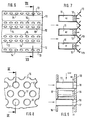
Die Fin. 1 bis 4 zeigen einen Brenner zum Verbrennen von H2 zum Einbau beispielsweise in die Brennkammer einer Gasturbine. Der Brenner hat eine plattenartige Gestalt und wird quer zur Hauptstromrichtung in die Brennkammer eingebaut. Der Randbereich des Brenners und dessen Verbindung mit dem nicht gezeigten Brennkammergehäuse ist nicht dargestellt und kann beliebig ausgebildet sein. Der Brenner besteht aus einer ersten Lochplatte 2 und einer zweiten Lochplatte 3, die durch eine Vielzahl von Führungsrohren 4 auf konstantem Abstand d gehalten werden. Dabei können die Löcher nach bestimmten Matrix-Mustern angeordnet sein. Die erste Lochplatte 2 besteht beispielsweise aus einem geeigneten Metall und ist gasundurchlässig. Die zweite Lochplatte 3 ist demgegenüber gasdurchlässig und besteht aus einem geeigneten porösen Material, beispielsweise aus einem Sintermetall. Dabei sind die Löcher in beiden Platten 2,3 deckungsgleich angebracht, so daß jedes Loch in der ersten Platte 2 mit dem zugeordneten Loch der zweiten Platte 3 ein Lochpaar bildet. Der Zusammenhalt des Brenners wird im wesentlichen dadurch hergestellt, daß in jedem Lochpaar ein Führungsrohr 4 als Abstandhalter eingesetzt und fixiert ist. Die Führungsrohre 4 weisen umlaufende nach außen gewalzte Sicken 5 auf. Die Fixierung der Führungsrohre 4 in der Lochplatte 2 erfolgt beispielsweise durch Löten oder Schweißen, wohingegen die Fixierung in der Platte 3 beispielsweise durch Einwalzen oder Bördeln erfolgen kann. Dabei ergibt sich im Zusammenwirken mit der Sicke 5 zwischen den Führungsrohren 4 und der Lochplatte 3 jeweils eine formschlüssige Verbindung. Damit bilden im wesentlichen die Lochplatten 2,3 mit den Führungsrohren 4 eine Verteilerkammer. In jedes Führungsrohr 4 ist ein Luftleitbolzen 6 eingesetzt, wie er in den Fign. 3 und 4 vergrößert gezeigt ist. Der Leitbolzen besteht im Grunde aus einem zylindrischen Rotationskörper mit einem Anschlag 6a, einem Führungsteil 6b, einer Halterung 8 und einer Scheibe 9. Der Außendurchmesser des Führungsteils 6b entspricht in etwa dem Innendurchmesser des Führungsrohres 4 und weist in der gezeigten Beispielausführung vier axiale Leitkanäle 7 auf. Die Halterung 8 ist in Fig. 3 rechts am Führungsteil angesetzt und stellt praktisch einen Bereich mit reduziertem Durchmesser dar, der die konzentrisch angesetzte Scheibe 9 trägt, deren Außendurchmesser ungefähr dem des Führungsteils 6b entspricht. Der Anschlag 6a wird durch einen in axialer Richtung kurzen Bereich gebildet, dessen Außendurchmesser größer ist als der des Führungsteils 6b. In jedes Führungsrohr 4 ist von der Luftseite des Brenners her ein Leitbolzen 6 eingesetzt bis der Anschlag 6a an der Lochplatte 2 anliegt und ist in dieser Position dauerhaft fixiert. Eine derartige Baugruppe bildet jeweils einen Injektor. Zur Inbetriebnahme des Brenners wird gasförmiger Wasserstoff in die zwischen den Lochplatten 2,3 bestehende Verteilerkammer eingeleitet. Außerdem wird Luft durch die Führungsrohre in die Brennkammer eingeblasen. Dabei strömt der Wasserstoff innerhalb der Verteilerkammer quer zur Hauptstromrichtung und verteilt sich dabei in einer Feinverteilung auf die örtlichen Bereiche der porösen Lochplatte 3, durch die er in die Brennkammer eintritt und hier eine Wasserstoffumgebung bildet. Dabei entsteht am Austritt jedes Führungsrohres 4 infolge der Umlenkung durch die Scheibe 9 eine Luftströmung nach Art eines Kegelmantels, die in einen Prozeß der Gemischbildung mit dem umgebenden Wasserstoff eintritt und dabei eine rotationssymmetrische Diffusionsflamme bildet. Förderlich für die Aktivierung des Mischprozesses ist hier die Wechselwirkung aufeinanderprallender benachbarter Kegelflammen. Die Geometrie der Leitbolzen 6 ist so gewählt, daß sich bei deren Einsetzen bis zum jeweiligen Anschlag 6a eine vorbestimmte Umlenkung, d. h. eine vorbestimmte Flammenform ergibt. Es ist auch denkbar, daß die Anschläge 6a aus Gewichtsgründen weggelassen werden. In diesem Falle erfolgt das Einsetzen der Leitbolzen 6 in die Führungsrohre 4 in eine vorbestimmte axiale Position mittels einer Fertigungsvorrichtung. Durch den äußerst einfachen Aufbau der Injektoren können diese so miniaturisiert werden, daß eine wesentlich größere Anzahl davon je Brennkammer installierbar ist. Infolge der Miniaturisierung in der angegebenen Größenordnung werden die erfindungsgemäß ausgebildeten Brennzonen Mikrobrennzonen genannt.Fin. 1 to 4 show a burner for burning H2 for installation, for example, in the combustion chamber of a gas turbine. The burner has a plate-like shape and is installed transversely to the main flow direction in the combustion chamber. The edge area of the burner and its connection to the combustion chamber housing, not shown, is not shown and can be of any design. The burner consists of a first
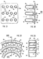
Die Fign. 6 und 7 zeigen eine weitere Ausgestaltung eines erfindungsgemäßen Brenners, bestehend aus einzelnen für den Wasserstoff vorgesehenen langgestreckten Verteilerkanälen 11 von U-förmigem Querschnitt, die zur Brennkammer hin durch Wandungen 12 aus einem porösen Sintermetall abgeschlossen sind. Die Kanäle 11 sind durch Lochprofile 13 von winkelförmigem Querschnitt in der Weise miteinander verbunden, daß jeweils die freien Längskanten eines Lochprofils 13 an den Längskanten zweier benachbarter Verteilerkanäle 11 befestigt sind. Dabei sind die Löcher 14 in den streifenförmigen Schenkeln der Lochprofile 13 in gleichmäßigem Abstand angebracht. Zur Inbetriebnahme dieses Brenners wird gasförmiger Wasserstoff in die Verteilerkanäle 11 eingeleitet. Gleichzeitig damit wird Luft durch die Bohrungen 14 in die Brennkammer eingeblasen. Dabei strömt der Wasserstoff innerhalb der Verteilerkanäle 11 quer zur Hauptstromrichtung und wird durch eine Feinverteilung auf die örtlichen Bereiche der porösen Wandungen 12 verteilt, durch die er in die Brennkammer eintritt und hier eine Wasserstoffumgebung bildet. Infolge der Luftzufuhr bildet sich im Bereich jeder Bohrung 14 eine stöchiometrische Zone, die bei Zündung des Brenners eine eigene Flamme bildet. Dieser Brenner ist besonders einfach ausgebildet und kann als Blechkonstruktion hergestellt werden. Dabei kann man beispielsweise so vorgehen, daß die U-förmigen Verteilerkanäle 11 aus Blech gebogen werden, wobei jeder U-Schenkel einstückig mit einem schräg abgewinkelten Lochstreifen verbunden ist. Nach dem Einsetzen der porösen Wandungen 12 werden benachbarte Kanäle 11 beispielsweise durch Verschweißen längs der freien Kanten der Lochstreifen miteinander verbunden. Dieser Brenner ist derart miniaturisierbar, daß mehrere Tausend Brennzonen innerhalb einer Brennkammer erreicht werden.The figures 6 and 7 show a further embodiment of a burner according to the invention, consisting of individual
Bei der in den vorbeschriebenen Brennern stattfindenden Feinverteilung wird das H2 über die Verteilerkammer bzw. über die Verteilerkanäle auf tausende von Mikrobrennzonen verteilt, so daß gleichsam eine Mikrodiffusionsverbrennung des Wasserstoffs stattfindet. Dadurch, daß bei den vorbeschriebenen Brennern innerhalb der Brennkammer eine Wasserstoffumgebung gebildet wird, in die Luftstrahlen injiziert werden, ergibt sich eine inverse Diffusionsverbrennung, die sich in den entstehenden Mischzonen mit meist turbulentem Verlauf stabilisieren kann. Der wesentliche Vorteil dieser inversen Wasserstoff-Diffusionsverbrennung besteht darin, daß eine gute Kühlung der Struktur durch das H2 erreicht wird.In the case of the fine distribution taking place in the burners described above, the H2 is distributed over the distribution chamber or via the distribution channels to thousands of micro-combustion zones, so that, as it were, microdiffusion combustion of the hydrogen takes place. The fact that the above-described burners form a hydrogen environment within the combustion chamber, into which air jets are injected, results in an inverse diffusion combustion, which can stabilize in the resulting mixing zones with a mostly turbulent course. The main advantage of this inverse hydrogen diffusion combustion is that the structure is cooled well by the H2.
Bei den vorgenannten Brennern können anstelle der porösen Sintermetalle auch andere poröse metallische Materialien verwendet werden. So kommen auch poröse Materialien auf der Basis metallischer Fasern in Betracht, wie sie beispielsweise unter der Bezeichnung "Felt Metal" bekannt sind. Weiterhin ist es denkar, daß das poröse Material aus einem Keramikwerkstoff besteht. Um die Auswirkungen von in einem porösen Material möglicherweise vorhandenen Inhomogenitäten zu begrenzen, kann ein Lochblech mit einem definierten feinen Lochraster einer relativ dünnen Schicht eines porösen Materials vorgeschaltet oder allein verwendet werden.With the aforementioned burners, other porous metallic materials can also be used instead of the porous sintered metals. Porous materials based on metallic fibers, such as are known, for example, under the name "felt metal", are also suitable. Furthermore, it is inconceivable that the porous material consists of a ceramic material. In order to limit the effects of inhomogeneities possibly present in a porous material, a perforated plate with a defined fine hole pattern can be placed upstream of a relatively thin layer of porous material or used alone.
Die Fign. 8 bis 11 zeigen eine weitere Ausgestaltung eines Brenners, der jedoch im Gegensatz zu den vorherigen nicht mit inverser sondern mit regulärer Diffusionsverbrennung arbeitet. Dieser Brenner besteht wieder im wesentlichen aus zwei deckungsgleichen Lochplatten, die hier mit 15 und 16 bezeichnet sind. Die beiden Lochplatten sind über Führungsrohre 17, die jeweils eine Eintrittsöffnung und eine Austrittsöffnung aufweisen, fest miteinander verbunden, so daß wieder eine Verteilerkammer gebildet wird. In der Nähe der Austrittsöffnungen sind mehrere Bohrungen 18 in gleicher Winkelteilung an den Führungsrohren 17 angebracht. In jedes Führungsrohr 17 ist ein Leitbolzen 19, bestehend aus einem Anschlag 20, einem Führungsteil 21 und einem Freistrahlteil 22, eingesetzt, wobei der Freistrahlteil praktisch einen axialen Abschnitt mit reduziertem Durchmesser darstellt. Der Anschlag 20 und der Führungsteil 21 weisen eine Anzahl axial verlaufender Nuten 23 auf, deren Tiefe bis zum Außendurchmesser des Freistrahlteils 22 reichen kann. Dabei stimmt die Anzahl der Bohrungen 18 mit der der Nuten 23 überein. Bei Inbetriebnahme des Brenners wird Luft durch die Führungsrohre 17 in die Brennkammer geblasen. Gleichzeitig wird H2 in die Verteilerkammer eingeleitet, so daß er durch die einzelnen Bohrungen 18 in die Führungsrohre injiziert und hier von der durch die Nuten 23 ankommenden Luft mitgenommen wird. Dabei entsteht jeweils stromab einer Bohrung 18 eine Mikrobrennzone, in der sich bei Zündung der Brennkammer eine Flamme stabilisiert. Da die Führungsrohre 17 in der gezeigten Beispielausführung jeweils sechs Bohrungen 18 aufweisen, ergeben sich je Führungsrohr sechs Mikrobrennzonen. Damit ergibt sich eine weitere Steigerung der Anzahl der Brennzonen. Eine Anwendung dieses Prinzips auf die eingangs genannte Brennkammer von TRUD würde die Anzahl der installierbaren Brennzonen auf ca. 5000 steigern. Dies wiederum bewirkt, daß auch ohne Vormischung ein sehr hoher Mischungsgrad erreicht wird, was zur Folge hat, daß die Entstehung von NOx weitgehend reduziert wird. Durch Drehung und/oder axiale Verschiebung der Leitbolzen 19 gegenüber den Führungsrohren 17 können verschiedene Einstellungen des Brenners vorgenommen werden. Auch hierbei besteht die Möglichkeit, die Anschläge 20 wegzulassen und die axiale Position der Luftleitbolzen anhand einer entsprechenden Vorrichtung einzustellen.The figures 8 to 11 show a further embodiment of a burner which, in contrast to the previous ones, does not work with inverse but with regular diffusion combustion. This burner again consists essentially of two congruent perforated plates, which are designated 15 and 16 here. The two perforated plates are firmly connected to one another via
Die Fign. 12 bis 15 zeigen verschiedene Einstellungen des vorbeschriebenen Brenners. In Fig. 12 ist der Leitbolzen mit den Nuten 23 gegenüber dem Führungsrohr 17 mit den Bohrungen 18 so eingestellt, daß die Injektion des Wasserstoffs durch die Bohrungen 18 in die Lücken zwischen den Luftstrahlen erfolgt, die durch die Nuten 23 ankommen. Fig. 13 zeigt den Leitbolzen in einer Position, in der der Führungsteil 21 bis dicht an die Bohrungen 18 heranreicht. Hierdurch kann der Wasserstoffstrahl nur stromab umgelenkt werden. Wird der Führungsteil 21 jedoch so in dem Führungsrohr 17 fixiert, daß ein etwas größerer Abstand zu den Bohrungen 18 besteht, wie in Fig. 14 gezeigt, so kann eine gewisse Rezirkulation eintreten. Fig. 15 zeigt schließlich eine Konfiguration, in der die durch die Nuten 23 ankommenden Luftstrahlen genau auf die durch die Bohrungen eintretenden Wasserstoffstrahlen treffen. In allen diesen Fällen werden feine Wasserstoffstrahlen mittels der Bohrungen 18 in eine Luftumgebung eingeleitet, so daß sich eine reguläre Diffusionsverbrennung ergibt, wobei die einzelnen Brennzonen nur noch Durchmesser in der Größenordnung von 2 mm aufweisen. Hierbei stabilisieren sich die Flammen in vielen Fällen an den Bohrungen 18. Erwähnt sei, daß der Freistrahl 22 in einer Ausgestaltung der Erfindung auch weggelassen werden kann, insbesondere bei Luftinjektion nach Fig. 15.The figures 12 to 15 show various settings of the burner described above. In Fig. 12, the guide pin with the
Die Figuren 16 und 17 zeigen eine Ausgestaltung, wobei die Wasserstoffstrahlen und die Luftstrahlen bis zu ihrem Eintritt in die Brennkammer getrennt geführt werden. Hierzu werden die vorbeschriebenen Führungsrohre 17 mit den Bohrungen 18 verwendet. Diese sind wieder in die Lochplatten 15 und 16 eingesetzt, wovon hier nur die mit 16 bezeichnete zu sehen ist. Der hier verwendete Leitbolzen 24 weist zwar wieder die Nuten 23 auf, ist aber sonst mit zwei wesentlichen Änderungen versehen. Zum einen ist der Bolzen mit konstantem Durchmesser annähernd bis zum Austrittsquerschnitt geführt. Zum anderen sind an den zwischen den Nuten 23 befindlichen Materialbereichen mittig kleine axial verlaufende Leitkanäle 25 angebracht. Der jeweilige Leitbolzen 24 ist so in das betreffende Führungsrohr 17 eingesetzt, daß jede Bohrung 18 in einen Leitkanal 25 einmündet. Hierdurch wird der Beginn der Diffusion zwischen Wasserstoff und Luft an einen Bereich stromab von der Lochplatte 16 gelegt, beispielsweise um exzessive thermische Strukurbelastungen zu vermeiden. Bei diesen Lösungen stabilisieren sich die Flammen an den Mündungen der Leitkanäle 25.FIGS. 16 and 17 show an embodiment in which the hydrogen jets and the air jets are guided separately until they enter the combustion chamber. For this purpose, the
Die Figuren 18 und 19 zeigen eine Ausgestaltung eines Brenners, für reguläre Diffusionsverbrennung vom zweidimensionalen Typus. Dieser Brenner besteht wieder aus einzelnen für das H2 vorgesehenen langgestreckten Verteilerkanälen 26, die jedoch im Gegensatz zu den Verteilerkanälen 11 nach den Fign. 6 und 7 einen geschlossenen Querschnitt aufweisen. Dieser Querschnitt wird im wesentlichen durch eine flache Recheckform bestimmt, die jedoch in ihrem im Bild rechten Bereich eine Dachkante 26a aufweist. Zu beiden Seiten der Dachkante sind feine Bohrungen 27 in versetzter Anordnung angebracht. Die einzelnen Kanäle 26 werden durch eine nicht gezeigte Halterung in einem gegenseitigen Abstand gehalten, so daß sie ein Gitter bilden, das gemäß Fig. 19 von links nach rechts von der Luft durchströmt werden kann. Der Brenner umfaßt weiterhin streifenförmige Lückenbleche 28, in deren Längskanten Lücken 29 eingearbeitet sind. Die Lückenbleche 28 sind jeweils zwischen zwei Verteilerkanälen 26 im Bereich der Bohrungen 27 durch eine nicht gezeigte Halterung so fixiert, daß jeder Bohrung 27 eine Lücke 29 zugeordnet ist. Dabei können statt der einen gezeichneten Bohrung 27 auch mehrere feinere Bohrungen angeordnet sein. Bei Inbetriebnahme dieses Brenners wird Luft entsprechend den Pfeilen 30 durch die Lücken 29 und H2 durch die Bohrungen 27 gemäß den Pfeilen 31 in die Brennkammer eingeblasen, wodurch innerhalb der Brennkammer eine Luftumgebung mit einer Vielzahl von Mikrobrennzonen in den jeweiligen Bereichen der Bohrungen 27 gebildet wird. Nach Zündung der Brennkammer stabilisieren sich die Flammen an den Bohrungen 27.FIGS. 18 and 19 show an embodiment of a burner for regular diffusion combustion of the two-dimensional type. This burner again consists of individual
Die Fign. 20 und 21 zeigen einen Brenner mit einer einteiligen Lochplatte 32 mit Löchern 32a, woran mehrere Verteilerkanäle 33 mittels Halterungen 34 befestigt sind. Die Verteilerkanäle 33 haben einen Langrundquerschnitt und weisen in ihrem der Lochplatte 32 zugewandten Bereich eine Vielzahl von Bohrungen 35 auf. Die Halterungen 34 können aus Draht oder Blech gebildet sein. Wie Fig. 21 zeigt, sind jedem Loch 32a der Lochplatte 32 zwei Bohrungen 35 zugeordnet, wodurch H2 gemäß den Pfeilen 37 austreten kann.The figures 20 and 21 show a burner with a one-piece
Bei Inbetriebnahme dieses Brenners wird Luft entsprechend den Pfeilen 36 durch die Lochplatte 32 in die Brennkammer eingeblasen, wodurch innerhalb der Brennkammer eine Luftumgebung mit einer Vielzahl von Mikrobrennzonen in den jeweiligen Bereichen der Bohrungen 35 gebildet wird. Nach Zündung der Brennkammer stabilisieren sich die Flammen an den Bohrungen 35.When this burner is started up, air is blown into the combustion chamber according to the
Die Fign. 22 und 23 zeigen eine weitere Ausgestaltung eines Brenners. Die Teilansicht nach Fig. 22 zeigt gekrümmte Verteilerkanäle 38, die Bestandteil eines ringförmigen Brenners sind und nach Fig.23 einen langrunden Querschnitt aufweisen. Hierbei bildet jeder Verteilerkanal einen geschlossenen Ring, der über einen eigenen Anschluß mit der Wasserstoffleitung verbunden ist. Der Zusammenhalt des Brenners wird beispielsweise durch zwischen den einzelnen Verteilerkanälen 38 angeordnete wellenförmige Separatoren 39 hergestellt, die mit den Verteilerkanälen 38 beispielsweise durch Schweißen verbunden sind. Die Separatoren 39 sind jeweils aus einem Blechstreifen gebildet und stellen einen hinreichenden Abstand zwischen den einzelnen Verteilerkanälen 38 für den Luftdurchtritt sicher. Es ist auch denkbar, daß ein Verteilerkanal 38 mit einem Separator 39 durch Wickeln zu einem scheibenförmigen oder ringförmigen Brenner vereinigt wird, so daß der Verteilerkanal 38 eine Spiralform erhält. Zur Schaffung einer Vielzahl von Mikrobrennzonen sind an dem Verteilerkanal 38 wieder Bohrungen angebracht, die hier mit 40 bezeichnet sind. Hier kreuzen sich jeweils zwei Wasserstoffstrahlen 41 in einem Punkt. Gemeinsames Merkmal der ringförmigen und der spiralförmigen Verteilerkanäle ist, daß sie eine gekrümmte Form aufweisen. Diese Brenner arbeiten im Prinzip nach der gleichen Wirkungsweise, wie die bereits in Verbindung mit den Fign. 18 bis 21 beschriebenen.The figures 22 and 23 show a further embodiment of a burner. The partial view according to FIG. 22 shows curved
Claims (21)
dadurch gekennzeichnet, daß als Oxidator Luft verwendet wird und die Querströmung mit einer Feinverteilung auf eine Vielzahl von einzelnen Mikrobrennzonen verbunden ist.A method of burning hydrogen in a diffusion combustion, wherein the hydrogen and an oxidizer are introduced into a burner, the main flow direction is further defined by the flow direction of the oxidizer, and the hydrogen is distributed in a cross flow substantially perpendicular to the main flow direction to the individual combustion zones becomes,
characterized in that air is used as the oxidizer and the cross flow is associated with a fine distribution over a large number of individual micro-combustion zones.
dadurch gekennzeichnet, daß in den einzelnen Mikrobrennzonen Luft in eine Wasserstoffumgebung eingeleitet wird.Method according to claim 1,
characterized in that air is introduced into a hydrogen environment in the individual micro-combustion zones.
dadurch gekennzeichnet, daß in den einzelnen Mikrobrennzonen Wasserstoff in eine Luftumgebung eingeleitet wird.Method according to claim 1,
characterized in that hydrogen is introduced into an air environment in the individual micro-combustion zones.
dadurch gekennzeichnet, daß die Verteilerkammer aus einer ersten Lochplatte (2) und einer zweiten Lochplatte (3) besteht, die durch eine Vielzahl von Führungsrohren (4) auf konstantem Abstand (d) gehalten werden und in jedes Führungsrohr (4) ein Luftleitbolzen (6) mit mehreren axialen Leitkanälen (7,23) eingesetzt ist.A burner for carrying out the method of burning hydrogen according to claim 1, wherein the burner comprises a distribution chamber of a substantially plate-like shape,
characterized in that the distribution chamber consists of a first perforated plate (2) and a second perforated plate (3) which are kept at a constant distance (d) by a plurality of guide tubes (4) and an air guide pin (6) in each guide tube (4) ) with several axial guide channels (7.23).
dadurch gekennzeichnet, daß die zweite Lochplatte (3) aus einem gasdurchlässigen porösen Material besteht.Burner according to claim 4,
characterized in that the second perforated plate (3) consists of a gas-permeable porous material.
dadurch gekennzeichnet, daß die Lochplatten (15,16) aus einem gasundurchlässigen Material bestehen.Burner according to claim 4,
characterized in that the perforated plates (15, 16) consist of a gas-impermeable material.
dadurch gekennzeichnet, daß der Luftleitbolzen (6) eine Halterung (8) mit einer Scheibe (9) aufweist.Burner according to one of claims 4 to 6,
characterized in that the air guide pin (6) has a holder (8) with a disc (9).
dadurch gekennzeichnet, daß der Luftleitbolzen (6,19) einen Führungsteil (21) und einen Freistrahlteil (22) aufweist.Burner according to one of claims 4 to 6,
characterized in that the air guide pin (6, 19) has a guide part (21) and a free jet part (22).
dadurch gekennzeichnet, daß der Luftleitbolzen (6,19,24) vom Eintrittsquerschnitt bis zum Austrittsquerschnitt des betreffenden Führungsrohres reicht und hier einen konstanten Durchmesser aufweist und an den zwischen den Nuten (23) befindlichen Materialbereichen mittig axial verlaufende Leitkanäle (25) angebracht sind.Burner according to one of claims 4 to 6,
characterized in that the air guide pin (6, 19, 24) extends from the inlet cross-section to the outlet cross-section of the guide tube in question and here has a constant diameter and axially extending guide channels (25) are attached to the material areas located between the grooves (23).
dadurch gekennzeichnet, daß der Verteilerkanal (11) einen U-förmigem Querschnitt aufweist, der zur Brennkammer hin durch Wandungen (12) aus einem porösen Material abgeschlossen ist und der Verteilerkanal (11) durch ein Lochprofil (13) von winkelförmigem Querschnitt in der Weise mit einem benachbarten Verteilerkanal verbunden ist, daß die freien Längskanten des Lochprofils (13) an den Längskanten der benachbarten Verteilerkanäle (11) befestigt sind.A burner for carrying out the method for burning hydrogen according to claim 1, wherein the burner comprises at least one distribution channel,
characterized in that the distribution channel (11) has a U-shaped cross section, which is closed towards the combustion chamber by walls (12) made of a porous material and the distribution channel (11) by a perforated profile (13) of an angular cross section in the same way an adjacent distribution channel is connected so that the free longitudinal edges of the perforated profile (13) are attached to the longitudinal edges of the adjacent distribution channels (11).
dadurch gekennzeichnet, daß der Verteilerkanal (11,26) einen geschlossenen Querschnitt von im wesentlichen flach recheckiger Form aufweist, der zur Brennkammer hin mit einer Vielzahl von Bohrungen (27) versehen ist.A burner for carrying out the method for burning hydrogen according to claim 1, wherein the burner comprises at least one distribution channel,
characterized in that the distribution channel (11, 26) has a closed cross section of essentially flat, rectangular shape, which is provided with a plurality of bores (27) towards the combustion chamber.
dadurch gekennzeichnet, daß Lückenbleche (28) jeweils zwischen zwei Verteilerkanälen (11,26) im Bereich der Bohrungen (27) so fixiert sind, daß jeder Bohrung (27) eine Lücke (29) zugeordnet ist.Burner according to claim 11,
characterized in that gap plates (28) are each fixed between two distributor channels (11, 26) in the region of the bores (27) in such a way that a gap (29) is associated with each bore (27).
dadurch gekennzeichnet, daß der Brenner eine einteilige Lochplatte (32) aufweist, woran mehrere Verteilerkanäle (33) mittels Halterungen (34) befestigt sind und jedem Loch der Lochplatte (32) eine Bohrung (35) oder eine Gruppe von Bohrungen (35) zugeordnet ist.Burner according to claim 11,
characterized in that the burner has a one-piece perforated plate (32), to which a plurality of distribution channels (33) are fastened by means of brackets (34) and a hole (35) or a group of holes (35) is assigned to each hole of the perforated plate (32) .
dadurch gekennzeichnet, daß der Verteilerkanal (11,26,33,38) eine gekrümmte Form aufweist.Burner according to one of claims 10 to 12,
characterized in that the distribution channel (11, 26, 33, 38) has a curved shape.
dadurch gekennzeichnet, daß der Brenner einen wellenförmigen Separator (39) aufweist.Burner according to claim 14,
characterized in that the burner has a wave-shaped separator (39).
dadurch gekennzeichnet, daß das poröse Material ein Sintermetall ist.Burner according to one of claims 5 to 15,
characterized in that the porous material is a sintered metal.
dadurch gekennzeichnet, daß das poröse Material ein Keramikmaterial ist.Burner according to one of claims 5 to 15,
characterized in that the porous material is a ceramic material.
dadurch gekennzeichnet, daß das poröse Material ein Material auf der Basis von Metallfasern ist.Burner according to one of claims 5 to 15,
characterized in that the porous material is a material based on metal fibers.
dadurch gekennzeichnet, daß dem porösen Material ein Lochblech mit einem definierten feinen Lochraster vorgeschaltet ist.Burner according to one of claims 5 to 15,
characterized in that a perforated plate with a defined fine hole pattern is connected upstream of the porous material.
dadurch gekennzeichnet, daß das poröse Material durch ein Lochblech mit einem definierten feinen Lochraster ersetzt wird.Burner according to one of claims 5 to 15,
characterized in that the porous material is replaced by a perforated plate with a defined fine hole pattern.
dadurch gekennzeichnet, daß der Luftleitbolzen (6,19) einen Anschlag (6a,20) aufweist.Burner according to one of claims 4 to 9,
characterized in that the air guide pin (6, 19) has a stop (6a, 20).
Applications Claiming Priority (2)
| Application Number | Priority Date | Filing Date | Title |
|---|---|---|---|
| DE19547506A DE19547506B4 (en) | 1995-12-19 | 1995-12-19 | Method and burner for burning hydrogen |
| DE19547506 | 1995-12-19 |
Publications (3)
| Publication Number | Publication Date |
|---|---|
| EP0780631A2 true EP0780631A2 (en) | 1997-06-25 |
| EP0780631A3 EP0780631A3 (en) | 1998-09-30 |
| EP0780631B1 EP0780631B1 (en) | 2003-10-29 |
Family
ID=7780607
Family Applications (1)
| Application Number | Title | Priority Date | Filing Date |
|---|---|---|---|
| EP96119733A Expired - Lifetime EP0780631B1 (en) | 1995-12-19 | 1996-12-10 | Method and burner for combustion of hydrogen |
Country Status (4)
| Country | Link |
|---|---|
| EP (1) | EP0780631B1 (en) |
| JP (1) | JP3830596B2 (en) |
| DE (2) | DE19547506B4 (en) |
| RU (1) | RU2152559C2 (en) |
Cited By (5)
| Publication number | Priority date | Publication date | Assignee | Title |
|---|---|---|---|---|
| WO2004103417A1 (en) * | 2003-05-22 | 2004-12-02 | Ntu Ventures Private Limited | Method and apparatus for sterilizing medical and laboratory instruments and devices |
| EP2930430A1 (en) * | 2014-04-07 | 2015-10-14 | Siemens Aktiengesellschaft | A burner tip and a burner for a gas turbine |
| FR3095497A1 (en) | 2019-04-24 | 2020-10-30 | Henri Becu | BURNER IN NANO FRIED MATERIALS FOR THE FLAME COMBUSTION OF A GAS PREMIXE OF THE OXIDIZER / FUEL TYPE |
| CN115355530A (en) * | 2022-08-12 | 2022-11-18 | 中国航发沈阳发动机研究所 | Head structure of hydrogen fuel combustion chamber with semi-cylindrical jet hole |
| WO2023179825A1 (en) * | 2022-03-23 | 2023-09-28 | Dürr Systems Ag | Burner device |
Families Citing this family (12)
| Publication number | Priority date | Publication date | Assignee | Title |
|---|---|---|---|---|
| DE102006046053B4 (en) * | 2006-09-28 | 2008-11-20 | Green Vision Holding B.V. | Non-premixed burner |
| US8261555B2 (en) * | 2010-07-08 | 2012-09-11 | General Electric Company | Injection nozzle for a turbomachine |
| UA102400C2 (en) * | 2011-01-24 | 2013-07-10 | Товариство З Обмеженою Відповідальністю "Науково-Проектний Інститут Хімічних Технологій "Хімтехнологія" | Burner for acetylene production reactor |
| US8893501B2 (en) * | 2011-03-28 | 2014-11-25 | General Eletric Company | Combustor crossfire tube |
| CA2950558C (en) | 2014-05-30 | 2020-10-20 | Kawasaki Jukogyo Kabushiki Kaisha | Combustor for gas turbine engine |
| EP3150918B1 (en) * | 2014-05-30 | 2019-12-18 | Kawasaki Jukogyo Kabushiki Kaisha | Combustion device for gas turbine engine |
| JP6535525B2 (en) * | 2015-07-01 | 2019-06-26 | 三菱日立パワーシステムズ株式会社 | Gas turbine combustor |
| EP3805107A1 (en) | 2019-10-08 | 2021-04-14 | Airbus SAS | Hybrid propulsion system for aircraft, method of operating a hybrid propulsion system, and a hybrid aircraft |
| JP7222872B2 (en) * | 2019-11-08 | 2023-02-15 | 株式会社デンソー | gas turbine combustor |
| RU2767237C1 (en) * | 2021-05-11 | 2022-03-17 | Федеральное государственное бюджетное учреждение науки Институт теоретической и прикладной механики им. С.А. Христиановича Сибирского отделения Российской академии наук (ИТПМ СО РАН) | Method for organizing diffusion combustion of a microjet of gaseous fuel |
| EP4173956A1 (en) | 2021-10-29 | 2023-05-03 | Airbus S.A.S. | Hybrid propulsion system for propelling an aircraft, method of operating same, and hybrid aircraft |
| KR20230091605A (en) | 2021-12-16 | 2023-06-23 | 한화에어로스페이스 주식회사 | Burner including channel arranged orthogonally |
Family Cites Families (13)
| Publication number | Priority date | Publication date | Assignee | Title |
|---|---|---|---|---|
| DE372932C (en) * | 1923-04-05 | Karol Hand | Gas heating burner head | |
| US1968395A (en) * | 1932-02-03 | 1934-07-31 | Carl L Zeller | Gas burner |
| AT299490B (en) * | 1968-10-10 | 1972-06-26 | British Petroleum Co | Burners for liquid and / or gaseous fuels |
| GB1263611A (en) * | 1969-05-19 | 1972-02-16 | British Petroleum Co | Gas burner |
| GB1343398A (en) * | 1969-12-24 | 1974-01-10 | Delaney Gallay Ltd | Gas burners |
| DE2034352C2 (en) * | 1970-07-10 | 1984-02-23 | Lanemark Ltd., Coventry | Gas burner of metal plate components - has tubular protrusions fitting together formed round plates apertures |
| JPS5245880Y2 (en) * | 1973-02-08 | 1977-10-19 | ||
| FR2226891A5 (en) * | 1973-04-20 | 1974-11-15 | Vitaly Fedorovich Popov | |
| FR2495280A1 (en) * | 1980-12-01 | 1982-06-04 | Deutsche Forsch Luft Raumfahrt | Steam generating system for driving turbine - uses hydrogen and oxygen fed into combustion chamber and having water injection |
| FR2628826B1 (en) * | 1988-03-21 | 1992-04-24 | Chaffoteaux Et Maury | IMPROVEMENTS ON GAS BURNERS |
| JPH0225612A (en) * | 1988-07-14 | 1990-01-29 | Shoei Seisakusho:Kk | Nozzle mixing gas burner |
| US5083917A (en) * | 1990-05-15 | 1992-01-28 | Cat Eye Co., Ltd. | Single port inshot target burner |
| JP2589218Y2 (en) * | 1993-10-07 | 1999-01-27 | 株式会社山形信越石英 | Quartz glass burner |
-
1995
- 1995-12-19 DE DE19547506A patent/DE19547506B4/en not_active Expired - Lifetime
-
1996
- 1996-12-10 EP EP96119733A patent/EP0780631B1/en not_active Expired - Lifetime
- 1996-12-10 DE DE59610797T patent/DE59610797D1/en not_active Expired - Lifetime
- 1996-12-18 RU RU96123903/06A patent/RU2152559C2/en active
- 1996-12-18 JP JP33840896A patent/JP3830596B2/en not_active Expired - Lifetime
Non-Patent Citations (1)
| Title |
|---|
| None |
Cited By (9)
| Publication number | Priority date | Publication date | Assignee | Title |
|---|---|---|---|---|
| WO2004103417A1 (en) * | 2003-05-22 | 2004-12-02 | Ntu Ventures Private Limited | Method and apparatus for sterilizing medical and laboratory instruments and devices |
| US7575715B2 (en) | 2003-05-22 | 2009-08-18 | Nanyang Technological University | Methods for sterilizing medical devices using a hydrogen surface-mixed diffusion flame |
| EP2930430A1 (en) * | 2014-04-07 | 2015-10-14 | Siemens Aktiengesellschaft | A burner tip and a burner for a gas turbine |
| WO2015154902A1 (en) * | 2014-04-07 | 2015-10-15 | Siemens Aktiengesellschaft | A burner tip and a burner for a gas turbine |
| US10125982B2 (en) | 2014-04-07 | 2018-11-13 | Siemens Aktiengesellschaft | Burner tip and a burner for a gas turbine |
| FR3095497A1 (en) | 2019-04-24 | 2020-10-30 | Henri Becu | BURNER IN NANO FRIED MATERIALS FOR THE FLAME COMBUSTION OF A GAS PREMIXE OF THE OXIDIZER / FUEL TYPE |
| WO2023179825A1 (en) * | 2022-03-23 | 2023-09-28 | Dürr Systems Ag | Burner device |
| CN115355530A (en) * | 2022-08-12 | 2022-11-18 | 中国航发沈阳发动机研究所 | Head structure of hydrogen fuel combustion chamber with semi-cylindrical jet hole |
| CN115355530B (en) * | 2022-08-12 | 2023-06-20 | 中国航发沈阳发动机研究所 | Hydrogen fuel combustion chamber head structure of semi-cylindrical jet hole |
Also Published As
| Publication number | Publication date |
|---|---|
| EP0780631A3 (en) | 1998-09-30 |
| JP3830596B2 (en) | 2006-10-04 |
| RU2152559C2 (en) | 2000-07-10 |
| DE19547506A1 (en) | 1997-07-03 |
| EP0780631B1 (en) | 2003-10-29 |
| DE19547506B4 (en) | 2008-06-05 |
| JPH09178128A (en) | 1997-07-11 |
| DE59610797D1 (en) | 2003-12-04 |
Similar Documents
| Publication | Publication Date | Title |
|---|---|---|
| DE2838258C2 (en) | Annular combustion chamber for a jet engine | |
| EP0780631B1 (en) | Method and burner for combustion of hydrogen | |
| EP1064498B1 (en) | Burner for a gas turbine | |
| DE3217674C2 (en) | Combustion chamber for a gas turbine | |
| DE69729505T2 (en) | How a gas turbine combustor works | |
| EP1730441B1 (en) | Device and method for stabilizing the flame in a burner | |
| EP1802915B1 (en) | Gas turbine burner | |
| EP2156095B1 (en) | Swirling-free stabilising of the flame of a premix burner | |
| DE69919764T2 (en) | combustion chamber | |
| CH698405A2 (en) | Injection. | |
| DE3835415A1 (en) | FUEL INJECTOR FOR A COMBUSTION CHAMBER OF A GAS TURBINE ENGINE | |
| DE3222347A1 (en) | VIBRATION BURNER WITH PRE-MIX | |
| CH703655A1 (en) | Premix FOR A GAS TURBINE. | |
| EP1356236B1 (en) | Premix burner and method for operating such a premix burner | |
| CH703548A2 (en) | Fuel injection head with surface features for flame stabilization and method for generating a fuel injection head. | |
| EP1918641A2 (en) | Burner device and method for injecting a fuel-oxidant mixture into a combustion chamber | |
| DE2255306C3 (en) | Aerodynamic flame holder for air-breathing jet engines | |
| EP1359376B1 (en) | Combustion chamber for gas turbine with precise fuel injection to increase the homogeneity of the air-fuel mixture | |
| EP0780638B1 (en) | Combustion chamber for gasturbine | |
| EP1235033B1 (en) | Annular combustor and method of operating the same | |
| DE2552374C2 (en) | Burners for liquid or gaseous fuel | |
| WO1999004196A1 (en) | Arrangement of burners for heating installation, in particular a gas turbine combustion chamber | |
| DE2542719A1 (en) | COMBUSTION CHAMBER | |
| EP1446610A1 (en) | Method of combustion, in particular methods for the production of electrical current and/or heat | |
| EP2171354B1 (en) | Burner |
Legal Events
| Date | Code | Title | Description |
|---|---|---|---|
| PUAI | Public reference made under article 153(3) epc to a published international application that has entered the european phase |
Free format text: ORIGINAL CODE: 0009012 |
|
| AK | Designated contracting states |
Kind code of ref document: A2 Designated state(s): DE FR GB |
|
| K1C1 | Correction of patent application (title page) published |
Effective date: 19970625 |
|
| PUAL | Search report despatched |
Free format text: ORIGINAL CODE: 0009013 |
|
| AK | Designated contracting states |
Kind code of ref document: A3 Designated state(s): DE FR GB |
|
| RAP3 | Party data changed (applicant data changed or rights of an application transferred) |
Owner name: DAIMLERCHRYSLER AEROSPACE AIRBUS GESELLSCHAFT MIT |
|
| 17P | Request for examination filed |
Effective date: 19980819 |
|
| 17Q | First examination report despatched |
Effective date: 20000919 |
|
| RAP1 | Party data changed (applicant data changed or rights of an application transferred) |
Owner name: EADS AIRBUS GMBH |
|
| RAP1 | Party data changed (applicant data changed or rights of an application transferred) |
Owner name: AIRBUS DEUTSCHLAND GMBH |
|
| GRAH | Despatch of communication of intention to grant a patent |
Free format text: ORIGINAL CODE: EPIDOS IGRA |
|
| GRAS | Grant fee paid |
Free format text: ORIGINAL CODE: EPIDOSNIGR3 |
|
| GRAA | (expected) grant |
Free format text: ORIGINAL CODE: 0009210 |
|
| AK | Designated contracting states |
Kind code of ref document: B1 Designated state(s): DE FR GB |
|
| REG | Reference to a national code |
Ref country code: GB Ref legal event code: FG4D |
|
| REG | Reference to a national code |
Ref country code: GB Ref legal event code: FG4C Free format text: NOTIFICATION HAS BEEN RECEIVED FROM THE EUROPEAN PATENT OFFICE THAT THE PUBLICATION LANGUAGE IS ACTUALLY GERMAN. |
|
| REF | Corresponds to: |
Ref document number: 59610797 Country of ref document: DE Date of ref document: 20031204 Kind code of ref document: P |
|
| GBT | Gb: translation of ep patent filed (gb section 77(6)(a)/1977) |
Effective date: 20040204 |
|
| ET | Fr: translation filed | ||
| PLBE | No opposition filed within time limit |
Free format text: ORIGINAL CODE: 0009261 |
|
| STAA | Information on the status of an ep patent application or granted ep patent |
Free format text: STATUS: NO OPPOSITION FILED WITHIN TIME LIMIT |
|
| 26N | No opposition filed |
Effective date: 20040730 |
|
| REG | Reference to a national code |
Ref country code: FR Ref legal event code: CD Owner name: AIRBUS OPERATIONS GMBH Effective date: 20111118 |
|
| REG | Reference to a national code |
Ref country code: FR Ref legal event code: PLFP Year of fee payment: 20 |
|
| PGFP | Annual fee paid to national office [announced via postgrant information from national office to epo] |
Ref country code: GB Payment date: 20151221 Year of fee payment: 20 Ref country code: DE Payment date: 20151210 Year of fee payment: 20 |
|
| PGFP | Annual fee paid to national office [announced via postgrant information from national office to epo] |
Ref country code: FR Payment date: 20151221 Year of fee payment: 20 |
|
| REG | Reference to a national code |
Ref country code: DE Ref legal event code: R071 Ref document number: 59610797 Country of ref document: DE |
|
| REG | Reference to a national code |
Ref country code: GB Ref legal event code: PE20 Expiry date: 20161209 |
|
| PG25 | Lapsed in a contracting state [announced via postgrant information from national office to epo] |
Ref country code: GB Free format text: LAPSE BECAUSE OF EXPIRATION OF PROTECTION Effective date: 20161209 |