EP0780271B1 - Sicherheitsgurtstrammer - Google Patents
Sicherheitsgurtstrammer Download PDFInfo
- Publication number
- EP0780271B1 EP0780271B1 EP96118531A EP96118531A EP0780271B1 EP 0780271 B1 EP0780271 B1 EP 0780271B1 EP 96118531 A EP96118531 A EP 96118531A EP 96118531 A EP96118531 A EP 96118531A EP 0780271 B1 EP0780271 B1 EP 0780271B1
- Authority
- EP
- European Patent Office
- Prior art keywords
- wall
- housing
- buckle
- anchor
- seat belt
- Prior art date
- Legal status (The legal status is an assumption and is not a legal conclusion. Google has not performed a legal analysis and makes no representation as to the accuracy of the status listed.)
- Expired - Lifetime
Links
Images


Classifications
-
- B—PERFORMING OPERATIONS; TRANSPORTING
- B60—VEHICLES IN GENERAL
- B60R—VEHICLES, VEHICLE FITTINGS, OR VEHICLE PARTS, NOT OTHERWISE PROVIDED FOR
- B60R22/00—Safety belts or body harnesses in vehicles
- B60R22/18—Anchoring devices
- B60R22/195—Anchoring devices with means to tension the belt in an emergency, e.g. means of the through-anchor or splitted reel type
- B60R22/1952—Transmission of tensioning power by cable; Return motion locking means therefor
Definitions
- the present invention relates to an apparatus for tensioning a vehicle seat belt, and particularly to a seat belt pretensioner which is connectable to a seat belt buckle.
- the known pretensioners are actuatable to tension a seat belt and tighten the seat belt against a vehicle occupant.
- One known pretensioner according to EP-A-186 880 is connected with a seat belt buckle.
- the buckle is connectable with a tongue carried by seat belt webbing.
- the pretensioner is actuatable to move the buckle in a direction which tensions the seat belt and tightens the seat belt against a vehicle occupant.
- the known pretensioner includes a cylinder fixed to the vehicle.
- a piston is located in the cylinder and moves in the cylinder.
- the piston is fixed to a first end of a cable.
- the cable has a second end fixed to the buckle. The second end of the cable extends at an angle relative to the direction of movement of the piston in the cylinder.
- An actuatable igniter is located adjacent the cylinder. Upon actuation of the igniter, the piston moves in the cylinder and pulls the first end of the cable in one direction. The second end of the cable pulls the buckle in a direction which is angled relative to the direction of movement of the first end of the cable to tension the seat belt and tighten the seat belt against the occupant.
- EP-A-540 922 which also relates to a seat belt pretensioner.
- This pretensioner acts directly on the seat belt in the vicinity of a regular seat belt tensioner.
- this pretensioner acts on a shoulder portion of the seat belt only.
- US-A-4,458,921 shows an apparatus for tensioning a vehicle seat belt and tightening the seat belt against a vehicle occupant.
- Said apparatus comprises a buckle, an anchor, a housing fixed to either the buckle or the anchor, said housing including a first wall and a longitudinal axis.
- Said apparatus further comprises a second wall in said housing and co-operating with said first wall to define opposite ends of an extensible chamber, said second wall being movable relative to said first wall in a first direction along the axis, and a connector fixed to said second wall and to the other one of said buckle and said anchor, wherein said connector extends through said first wall.
- actuatable means are provided for delivery of a pressurized fluid into the expansible chamber for applying upon actuation a fluid pressure force against said first and second walls to expand said expansible chamber for moving said buckle in the first direction along the axis to tension the seat belt and tighten the belt against an occupant.
- an apparatus for tensioning a vehicle seat belt as set forth in claim 1 is provided.
- Preferred embodiments of the invention are claimed in the dependent claims.
- the present invention is directed to an apparatus for tensioning a vehicle seat belt and tightening the seat belt against a vehicle occupant.
- the apparatus comprises a buckle which is connectable with a tongue of the seat belt.
- An anchor is connectable to a part of the vehicle.
- a housing is fixed to one of the buckle and the anchor.
- the housing includes a first wall.
- a second wall is received in the housing opposite the first wall to at least partially define a chamber in the housing which is expansible.
- a connector is fixed to the second wall and to the other of the buckle and the anchor. The connector extends through the first wall.
- Actuatable means is in fluid communication with the chamber for directing, upon actuation, a fluid pressure force against the first wall and the second wall. The force expands the chamber and provides relative movement between the housing and the second wall to tension the seat belt and tighten the seat belt against the occupant.
- the second wall and the chamber each preferably have a rectangular periphery taken in a direction which extends normal to a longitudinal axis of the housing.
- a gasket is fixed to the second wall and engages the housing to inhibit fluid flow between the housing and the second wall.
- the second wall is fixed to the anchor.
- the actuatable means is fixed to the housing and is movable with the housing relative to the anchor and the second wall.
- the housing is fixed to the anchor and the second wall is fixed to the buckle.
- the actuatable means is fixed to the second wall and is movable relative to the anchor and the housing.
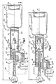
- a vehicle occupant seat belt system includes a buckle assembly 20 (Fig. 1) and seat belt webbing (not shown).
- the buckle assembly 20 is attached to a component of the vehicle, such as a seat, door, floor or door pillar.
- the seat belt webbing is extendable about an occupant of a vehicle seat.
- the seat belt webbing carries a tongue (not shown) which is connectable with the buckle assembly 20 to secure the seat belt webbing about the occupant.
- the buckle assembly 20 includes a buckle 22 having a cover 24, a movable pushbutton 26 extending through the cover, and a longitudinal axis A.
- the buckle 22 receives and latches the tongue to connect together the seat belt webbing and the buckle assembly 20.
- the buckle 22 is actuatable to release the tongue when the pushbutton 26 is manually depressed.
- the buckle assembly 20 also includes a pretensioner 40, constructed according to one embodiment of the present invention.
- the pretensioner 40 is operatively connected with the buckle 22.
- the pretensioner 40 is automatically actuatable to tension the seat belt and tighten the seat belt against the occupant in response to an event that requires tensioning of the seat belt and tightening the seat belt against the occupant.
- the pretensioner 40 includes a hollow housing 42 (Figs. 1-4) which is fixed to the buckle 22 by a connector 44.
- the connector 44 may be of any suitable length and extends in a direction substantially parallel to the axis A of the buckle 22.
- the housing 42 and the connector 44 are preferably made as one piece of metal, such as by die casting.
- the housing 42 has a longitudinal axis B which is substantially coaxial with the axis A of the buckle 22.
- the housing 42 includes a tube portion 46 which has a rectangular inner periphery, in a plane extending normal to the axis B.
- the housing 42 also includes an enlarged end portion 48 extending from the tube portion 46.
- the tube portion 46 is in fluid communication with the enlarged end portion 48.
- the enlarged end portion 48 has an opening 62 to the left, as viewed in Figs. 2-4.
- a first end wall or cap 64 is fixed in the opening 62 of the enlarged end portion 48 by suitable means, such as a weld or an adhesive.
- the cap 64 is preferably made from metal and supports an actuatable igniter 66.
- the igniter 66 has an end surface 67 located in the enlarged end portion 48 of the housing 42.
- An end portion 68 of the cap 64 is deformed over a flange 69 of the igniter 66 to retain the igniter in the cap.
- a circular opening 70 extends through the end cap 64 around the axis B of the housing 42.
- An anchor 80 is secured to the component of the vehicle by a suitable fastener, such as a bolt.
- a connector or cable 82 is fixed at one end to the anchor 80.
- the cable 82 is substantially inextendable in a direction along its length, measured in a direction parallel to the axis B, but is somewhat flexible in a direction transverse to its length.
- the cable 82 extends through the opening 70 in the cap 64.
- the outer diameter of the cable 82 fits tightly in the opening 70, and the cable forms a seal against the surface of the cap 64 defining the opening 70. It will be appreciated that a resilient seal could be provided in or at the opening 70 to engage the exterior of the cable 82.
- a bellows 83 is provided at the enlarged end portion 48 of the housing 42 to inhibit access to the cable 82, the igniter 66, and the enlarged end of the housing.
- the buckle 22 is initially spaced from the anchor 80 a distance D1 prior to actuation of the pretensioner 40.
- An end of the cable 82 opposite the end connected to the anchor 80 is connected to a second end wall or piston 84.
- the piston 84 is located in the tube portion 46 of the housing 42.
- the piston 84 has a rectangular outer periphery, in a plane extending normal to the axis B of the housing 42, and closely fits within the tube portion 46 of the housing.
- the piston 84 cooperates with the housing 42 and the cap 64 to define an expansible chamber 102.
- a rectangular elastomeric gasket 104 is fixed to the piston 84 and engages the inner periphery of the tube portion 46. The gasket 104 inhibits fluid flow between the piston 84 and the surfaces defining the tube portion 46 of the housing 42.
- the piston 84 and gasket 104 also cooperate with the tube portion 46 of the housing 42 to define a contractible chamber 105 on a side of the piston opposite the expansible chamber 102.
- a vent opening 107 is provided in the tube portion 46 of the housing 42. The vent opening 107 fluidly communicates the contractible chamber 105 with the environment external to the housing 42. Such fluid communication assures that fluid damping does not occur during movement of the piston 84 relative to the housing 42 when the chamber 102 expands.
- the end surface 67 of the igniter 66 is located in the chamber 102.
- the igniter 66 is actuated by an electrical signal communicated over wires 106.
- the igniter 66 upon actuation, produces combustion products.
- the combustion products flow from the igniter 66 into the chamber 102 in the enlarged end portion 48 of the housing 42.
- the pressure of the combustion products in the chamber 102 applies a force to surfaces of the piston 84, tube portion 46 of the housing 42, enlarged end portion 48 of the housing, and cap 64, all of which define the chamber.
- the force expands the chamber 102 to move the housing 42, the cap 64 and the igniter 66 linearly to the left, as viewed in Figs. 2-4, relative to the piston 84, the cable 82 and the anchor 80 and in a direction along the axis A of the buckle 22.
- the chamber 105 contracts concurrently with expansion of the chamber 102. Fluid in the chamber 105 escapes through the vent opening 107 in the housing 42 upon contraction of the chamber when the piston 84 moves within the housing. Movement of the housing 42 to the left pulls the connector 44 and the buckle 22 in a direction towards the anchor 80 to tension the seat belt and tighten the seat belt against the occupant.
- the buckle 22 moves closer to the anchor 80 in a direction along the axis B of the housing 22, from the distance D1 (Fig. 2) to the distance D2 (Fig. 3).
- the piston 84 has a pair of recesses 122 formed in opposite sides of the piston.
- Each recess 122 has a planar surface which extends at a relatively small angle relative to the axis B of the housing 42.
- a roller 124 and a resilient biasing gasket 126 are located in each recess 122. The rollers 124 and recesses 122 act on the tube portion 46 of the housing 42 to inhibit contraction of the chamber 102 but not expansion of the chamber, as will be explained.
- the housing 42 moves to the left relative to the piston 84, as viewed in Figs. 2-4.
- the rollers 124 are forced against and compress the gaskets 126 by friction of opposite walls of the tube portion 46 of the housing 42 moving relative to the piston 84.
- the resiliency of the biasing gaskets 126 urge the rollers 124 outward relative to the axis B along the planar surfaces defining the recesses 122.
- the rollers 124 wedge between the opposite walls of the tube portion 46 and the planar surfaces of the recesses 122 of the piston 84. The rollers 124 thus inhibit the housing 42 from moving to the right relative to the piston 84, as viewed in Figs. 2-4, and thus inhibit contraction of the chamber 102.
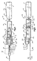
- Another buckle assembly 220 (Figs. 5 and 6) includes the buckle 22, illustrated in Figs. 1-4 and described above, and a pretensioner 240, constructed according to another embodiment of the present invention.
- the pretensioner 240 is actuatable to tension the seat belt and tighten the seat belt against the occupant in response to an event that requires tensioning of the seat belt and tightening the seat belt against the occupant.
- the pretensioner 240 includes a metal tubular housing 242 fixed to the buckle 22 by a metal connector 244.
- the housing 242 has a longitudinal axis C which extends coaxially with the axis A of the buckle 22.
- the housing 242 has a rectangular inner periphery, in a plane extending normal to the axis C of the housing.
- the left end portion 246 of the housing 242, as viewed in Fig. 6, is open, while the right end portion 248 is closed.
- a first wall or metal cap 264 is fixed to the left end portion 246 of the housing 242 to substantially close the left end portion.
- the cap 264 supports an actuatable igniter 266.
- a slot 270 is formed between the cap 264 and a lower wall of the housing 242, as viewed in Fig. 6.
- a connector or intermediate plate portion 282 of a one piece, flat element that also includes an anchor 280 at one end of the intermediate plate portion and a second wall or end member 284 at the other end of the intermediate plate portion.
- the anchor 280 is generally circular with a central opening 283.
- the anchor 280 is attachable to a component of the vehicle by a suitable fastener, such as a bolt, which extends through the opening 283. It will be apparent that the anchor 280 could be attached to the vehicle component in a manner which allows rotation of the anchor about the center of the opening 283 in the anchor.
- the intermediate plate portion 282 which is preferably coplanar with the anchor 280, is substantially inextendable in a direction along its length, measured in a direction parallel to the axis C, and is relatively rigid in a direction transverse to its length.
- the intermediate plate portion 282 fits tightly within the slot 270 so relatively little fluid flow or leakage can occur between the housing 242, the intermediate plate portion, and the cap 264. It will be apparent that the intermediate plate portion 282 and the anchor 280 could be disposed at an angle to one another or could be formed from separate parts that are subsequently fixed together.
- the end member 284 extends in a direction substantially normal to the extent of the intermediate plate portion.
- the end member 284 is located in the housing 242 and has a rectangular outer periphery, in a plane extending normal to the axis C of the housing 242.
- the housing 242, the cap 264, the end member 284, and the intermediate plate portion 282 cooperate to define an expansible chamber 302.
- the chamber 302 is expandable in a direction parallel to the axis A of the buckle 22.
- the housing 242 and the cap 264 are movable linearly on the axis A of the buckle 22 relative to the end member 284, intermediate plate portion 282, and anchor 280.
- the closed right end portion 248 of the housing 242, as viewed in Fig. 6, could be provided with at least one pressure relief or vent opening 303.
- the vent opening 303 would allow any fluid in the housing 242 to the right of the end member 284, as viewed in Fig. 6, to exit the housing during movement of the end second wall to the right.
- the pressure relief opening would assure that little or no fluid damping of the end member 284 occurs during expansion of the chamber 302.
- the igniter 266 has an end 268 in fluid communication with the expansible chamber 302.
- the igniter 266, upon actuation, produces combustion products.
- the combustion products flow from the igniter 266 into the chamber 302.
- the pressure of the combustion products in the chamber 302 applies a force to the surfaces of the end member 284, cap 264 and housing 242 to expand the chamber. Expansion of the chamber 302 forces the housing 242, the end cap 264 and the igniter 266 to move to the left, as viewed in Figs. 5-6, relative to the end member 284, intermediate plate portion 282 and anchor 280.
- the housing 242 pulls the buckle 22 in a direction towards the anchor 280 for tensioning the seat belt and tightening of the seat belt against the occupant.
- the end member 284 and intermediate plate portion 282 carry a structure 322 for inhibiting contraction of the chamber 302.
- the structure 322 includes a pawl 290 that is supported for pivotal movement on a shaft 292 in a mounting 293.
- the mounting 293 is fixed to the intermediate plate portion 282 and the end member 284.
- the pawl 290 is biased by a spring 294 to pivot in a clockwise direction, as viewed in Fig. 6.
- the pawl 290 pivots in a counterclockwise direction as a result of movement of the housing 242 to the left relative to the end member 284.
- the pawl 290 pivots in a clockwise direction under the bias of the spring 294 and wedges against the upper wall of the housing, as viewed in Fig. 6. Wedging of the pawl 290 against the housing 242 inhibits the housing from moving to the right relative to the end member 284 and contracting the chamber 302 due to a force applied to the seat belt by the occupant.
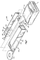
- FIG. 7-8 Another buckle assembly 420 (Figs. 7-8) includes the buckle 22, illustrated in Figs. 1-6 and described above.
- the buckle assembly 420 also includes a pretensioner 440, constructed according to yet another embodiment of the present invention.
- the pretensioner 440 is actuatable to tension the seat belt and tighten the seat belt against the occupant in response to an event that requires tensioning of the seat belt and tightening the seat belt against the occupant.
- the pretensioner 440 includes a metal tubular housing 442 having a longitudinal axis D which extends coaxially with the axis A of the buckle 22.
- the housing 442 is connected to an anchor 444 by suitable means, such as a weld.
- the anchor 444 is secured to a component of the vehicle by a suitable fastener, such as a bolt.
- the housing 442 has a rectangular inner periphery, in a plane extending normal to the axis D of the housing.
- the left end of the housing 442, as viewed in Fig. 8, is open.
- a first wall or end plate 446 is fixed to the housing 442 to close partially the right end of the housing and define a pair of parallel but spaced apart slots 460 (Fig. 7).
- the end plate 446 is a bent portion of the lower wall of the housing 442, as viewed in Figs. 7 and 8.
- the end plate 446 is fixed to the upper wall, such as by a weld 462.
- a mounting 464 is fixed to the buckle 22.
- the mounting 464 is fixed at its left end to the right ends of a pair of connectors or intermediate plates 482.
- the intermediate plates 482 are connected together at their left ends by a second wall or end member 484.
- Each of the intermediate plates 482 extends through a respective one of the slots 460 at the end plate 446 in the housing 442 and closely fits within the slot.
- the end member 484 is received in and movable relative to the housing 442 on the axis D of the housing and on the axis A of the buckle 22.
- the end member 484 has a rectangular outer periphery, in a plane extending normal to the axis D of the housing 442.
- the end member 484 cooperates with the housing 442 and the end plate 446 to define an expansible chamber 502.
- the end member 484 defines a movable left end of the expansible chamber 502.
- a block 486 is fixed between the intermediate plates 482 by tangs 487 on the intermediate plates to support an actuatable igniter 488.
- the igniter 488 has an end in fluid communication with the expansible chamber 502. Upon actuation of the igniter 488, combustion products are produced. The combustion products flow from the igniter 488 into the chamber 502. The pressure of the combustion products in the chamber 502 applies a force to the surfaces of the end member 484, end plate 446 and walls of the housing 442 to expand the chamber.
- the force of the pressure of the combustion products moves the end member 484 relative to the housing 442 to the left, as viewed in Fig. 8.
- the igniter 488 is movable with the end member 484 and intermediate plates 482 relative to the anchor 444 and the housing 442.
- the end member 484 and intermediate plates 482 pull the buckle 22 in a direction toward the anchor 444 for tensioning the seat belt and tightening the seat belt against the occupant.
- the pretensioner 440 could be modified so the end member 484 carries the igniter 488.
- the block 486 could thus be eliminated entirely.
- the block 486 could also be fixed to the intermediate plates 482 so the block defines a left end of the expansible chamber 502 which is movable relative to the housing 442.
- the end member 484 could thus be eliminated.
- the buckle assembly 520 includes the buckle assembly 420 in its entirety.
- the buckle assembly 520 also includes a structure 522 in the pretensioner 440 for inhibiting contraction of the chamber 502.
- the structure 522 is similar to the structure 322 illustrated in Fig. 6 and described above.
- the structure 522 does not inhibit movement of the intermediate plates 482 and end member 484 to the left relative to the housing 442, as viewed in Fig. 9.
- the structure 522 inhibits movement of the intermediate plates 482 and end member 484 to the right relative to the housing 442.
- the structure 522 includes a pawl 524 which is pivotable about a shaft that is fixed to both of the intermediate plates 482.
- the structure 522 is movable with the intermediate plates 482 relative to the housing 442.
- the pawl 524 engages the lower wall of the housing, as viewed in Fig. 9. Movement of the end member 484 and intermediate plates 482 to the right relative to the housing 442 is inhibited by the pawl 524 wedging against the lower wall of the housing.
- Fig. 10 illustrates yet another buckle assembly 620.
- the buckle assembly 620 is similar to the buckle assembly 420, illustrated in Figs. 7 and 8 and described above.
- the buckle assembly 620 is a modified version of the buckle assembly 420.
- the buckle assembly 620 includes the buckle 22 and a pretensioner 640.
- the pretensioner 640 has an actuatable igniter 688 which is carried in an end plate 664 of a housing 642.
- the igniter 688 is located between the intermediate plates 482. Upon actuation of the igniter 688, the end member 484 and intermediate plates 482 move to the left relative to the housing 642, as viewed in Fig. 10. The igniter-688 does not move relative to the anchor 444 and housing 642.
Landscapes
- Engineering & Computer Science (AREA)
- Mechanical Engineering (AREA)
- Automotive Seat Belt Assembly (AREA)
Claims (14)
- Eine Vorrichtung zum Spannen eines Fahrzeugsitzgurtes und zum Spannen eines Sitzgurtes gegenüber einem Fahrzeuginsassen, wobei die Vorrichtung folgendes aufweist:einen mit einer Zunge eines Sitzgurtes verbindbaren Verschluß (22);einen mit einem Teil eines Fahrzeugs verbindbaren Anker (80, 280; 444);ein Gehäuse (42; 242; 442; 642) befestigt an dem Verschluß (22) und/oder dem Anker (80; 280; 444) des Gehäuses einschließlich einer ersten Wand (64; 264; 446; 664) und einer Längsachse (B; C; D);eine zweite Wand (84; 284; 484) im Gehäuse und zusammenarbeitend mit der ersten Wand (64; 264; 446; 664) zur Definition von entgegengesetzten Enden einer ausdehnbaren Kammer (102; 302; 502), wobei die zweite Wand (84; 284; 484) relativ zur ersten Wand (64; 264; 446; 664) in einer ersten Richtung entlang der Achse (B; C; D) bewegbar ist;einen Verbinder (82; 282; 482) befestigt an der zweiten Wand (84; 284; 444) und mit dem entsprechenden anderen Element, also entweder dem Verschluß (22) oder dem Anker (80; 280; 444), wobei der Verbinder (82; 282; 482) sich durch die erste Wand (64; 264; 446; 664) erstreckt; undbetätigbare Mittel (66; 266; 488; 688) getragen von der einen der ersten bzw. der zweiten Wand, wobei die betätigbaren Mittel im wesentlichen parallel zu den Wänden und Verbinder angeordnet sind und in Strömungsmittelverbindung stehen mit der ausdehnbaren Kammer (102; 302; 502), zum Anlegen, beim Betätigen, einer Strömungsmitteldruckkraft gegen die ersten und zweiten Wände, um die ausdehnbare Kammer auszudehnen zur Bewegung des Verschlusses (22) in die erste Richtung entlang der Achse (B; C; D) um den Sitzgurt zu spannen und den Sitzgurt gegen den Insassen festzuziehen.
- Vorrichtung nach Anspruch 1, wobei das Gehäuse (42; 242; 442; 642) rohrförmig ist und einen rechteckigen Innenumfang besitzt, und zwar in einer Ebene, die sich senkrecht zu der Längsachse (B; C; D) des Gehäuses (42; 242; 442; 642) und wobei die zweite Wand (84; 284; 484) einen rechteckigen Außenumfang in der Ebene besitzt.
- Vorrichtung nach Anspruch 1, wobei die zweite Wand (84; 284) mit dem Anker (80; 280) verbunden ist, wobei das Gehäuse (42; 242) und die erste Wand (64; 264) relativ zur zweiten Wand bewegbar sind, und zwar ansprechend auf die Betätigung der betätigbaren Mittel (66; 266).
- Vorrichtung nach Anspruch 3, wobei die betätigbaren Mittel (66; 266) an der ersten Wand (64; 264) befestigt sind und sich mit der ersten Wand relativ zu der zweiten Wand (84; 284) bewegen.
- Vorrichtung nach Anspruch 1, wobei die zweite Wand (484) mit dem Verschluß (22) durch den Verbinder (482) verbunden ist, und wobei die zweite Wand (484) relativ zum Gehäuse (442) und der ersten Wand (446) bewegbar ist, und zwar infolge der Betätigung der betätigbaren Mittel (488; 688).
- Vorrichtung nach Anspruch 5, wobei die betätigbaren Mittel (488) an der zweiten Wand (484) befestigt sind, und wobei die betätigbaren Mittel mit der zweiten Wand relativ zur ersten Wand (446) bewegbar sind.
- Vorrichtung nach Anspruch 5, wobei die betätigbaren Mittel (688) an der ersten Wand (664) befestigt sind.
- Vorrichtung nach Anspruch 1, wobei ferner eine Dichtung (104) an der zweiten Wand (84) befestigt ist, und zwar zum Eingriff mit dem Gehäuse (42), um die Kammer (102) abzudichten.
- Vorrichtung nach Anspruch 1, wobei ferner Mittel (124; 290; 524) vorgesehen sind, um das Zusammenziehen der ausdehnbaren Kammer (102; 302; 502) nach der Ausdehnung der ausdehnbaren Kammer zu verhindern.
- Vorrichtung nach Anspruch 9, wobei die Verhinderungsmittel (290; 524) in der Kammer (302; 502) angeordnet sind.
- Vorrichtung nach Anspruch 1, wobei die zweite Wand (84; 284) und das Gehäuse (42; 242) zusammenarbeiten, um eine zusammenziehbare Kammer (105) auf einer Seite der zweiten Wand (84; 284) zu definieren, und zwar entgegengesetzt zu der ausdehnbaren Kammer (102; 302) und ferner mit einer Öffnung (107 303) durch das Gehäuse (42; 242), um die zusammenziehbare Kammer zu belüften.
- Vorrichtung nach Anspruch 1, wobei der Verschluß (22) anfangs von dem Anker (80; 280; 444) beabstandet ist, und zwar um einen ersten Abstand vor dem Ausdehnen der ausdehnbaren Kammer (102; 302; 502) und einen zweiten Abstand, der kleiner ist als der erste Abstand nach der Ausdehnung der ausdehnbaren Kammer.
- Vorrichtung nach Anspruch 1, wobei die zweite Wand einen Kolben (84) aufweist verbunden mit dem Anker (80) durch ein Kabel (82).
- Vorrichtung nach Anspruch 1, wobei die zweite Wand (284) eine Platte geformt in einem Stück mit dem Anker (280) aufweist, und wobei die Platte sich in einer Richtung quer zu einer Ebene erstreckt, die den Anker (280) enthält.
Applications Claiming Priority (2)
| Application Number | Priority Date | Filing Date | Title |
|---|---|---|---|
| US575836 | 1995-12-20 | ||
| US08/575,836 US5671949A (en) | 1995-12-20 | 1995-12-20 | Seat belt pretensioner |
Publications (3)
| Publication Number | Publication Date |
|---|---|
| EP0780271A2 EP0780271A2 (de) | 1997-06-25 |
| EP0780271A3 EP0780271A3 (de) | 1997-07-02 |
| EP0780271B1 true EP0780271B1 (de) | 2003-02-05 |
Family
ID=24301903
Family Applications (1)
| Application Number | Title | Priority Date | Filing Date |
|---|---|---|---|
| EP96118531A Expired - Lifetime EP0780271B1 (de) | 1995-12-20 | 1996-11-19 | Sicherheitsgurtstrammer |
Country Status (3)
| Country | Link |
|---|---|
| US (1) | US5671949A (de) |
| EP (1) | EP0780271B1 (de) |
| DE (1) | DE69626094T2 (de) |
Families Citing this family (25)
| Publication number | Priority date | Publication date | Assignee | Title |
|---|---|---|---|---|
| DE29605818U1 (de) * | 1996-03-28 | 1996-07-25 | Trw Occupant Restraint Systems Gmbh, 73551 Alfdorf | Fahrzeuginsassen-Rückhaltesystem mit einem Gurtstraffer |
| DE29608192U1 (de) * | 1996-05-06 | 1996-09-05 | Trw Occupant Restraint Systems Gmbh, 73551 Alfdorf | Gurtschloß für einen Sicherheitsgurt |
| US5863009A (en) * | 1997-12-24 | 1999-01-26 | Trw Vehicle Safety Systems Inc. | Apparatus for pretensioning seat belt webbing |
| DE19837927C2 (de) * | 1998-08-20 | 2001-07-12 | Breed Automotive Tech | Vorrichtung zum Straffen eines Kraftfahrzeugsicherheitsgurtes |
| DE29818655U1 (de) * | 1998-10-20 | 1999-05-27 | TRW Occupant Restraint Systems GmbH & Co. KG, 73553 Alfdorf | Schloßstraffer |
| US6142524A (en) * | 1998-12-14 | 2000-11-07 | Trw Vehicle Safety Systems Inc. | Seat belt pretensioner apparatus |
| US6076856A (en) * | 1999-01-12 | 2000-06-20 | General Motors Corporation | Belt tension and energy absorbing apparatus |
| US6264281B1 (en) * | 1999-08-25 | 2001-07-24 | Daimlerchrysler Corporation | Seat belt buckle pretensioner mounting mechanism |
| US6195996B1 (en) | 1999-12-21 | 2001-03-06 | Trw Inc. | Body of gas generating material for a vehicle occupant restraint |
| JP3836708B2 (ja) * | 2001-11-13 | 2006-10-25 | 株式会社東海理化電機製作所 | プリテンショナ装置 |
| DE10227755B4 (de) * | 2002-06-21 | 2004-07-22 | Autoliv Development Ab | Pyrotechnischer Schloßstraffer |
| US6902195B2 (en) | 2002-09-10 | 2005-06-07 | Trw Vehicle Safety Systems Inc. | Seat belt pretensioner |
| DE102006053563B4 (de) * | 2006-11-14 | 2022-05-12 | Mercedes-Benz Group AG | Gurtstraffer für ein Sicherheitsgurtsystem |
| JP5182843B2 (ja) * | 2007-02-15 | 2013-04-17 | テイ・エス テック株式会社 | 車両用シート |
| JP5294444B2 (ja) * | 2007-10-02 | 2013-09-18 | テイ・エス テック株式会社 | 車両用シート |
| US7823924B2 (en) * | 2008-06-24 | 2010-11-02 | Autoliv Asp, Inc. | Seatbelt pretensioner for a vehicle |
| US8585090B2 (en) | 2010-06-29 | 2013-11-19 | Autoliv Asp, Inc. | High efficiency pretensioner |
| DE102011117056B4 (de) * | 2011-10-27 | 2024-03-21 | Zf Automotive Germany Gmbh | Gurtstraffer für ein Sicherheitsgurtsystem |
| US8528987B2 (en) | 2012-01-30 | 2013-09-10 | Autoliv Asp, Inc. | Linear seat belt pretensioner |
| DE102012002719A1 (de) | 2012-02-14 | 2013-08-14 | Trw Automotive Gmbh | Pyrotechnischer Straffer |
| JP6341893B2 (ja) * | 2015-07-22 | 2018-06-13 | 株式会社東海理化電機製作所 | バックル装置 |
| JP6211115B2 (ja) * | 2016-02-10 | 2017-10-11 | 株式会社東海理化電機製作所 | バックル装置 |
| DE102016104226B4 (de) | 2016-03-08 | 2022-01-05 | Autoliv Development Ab | Straffvorrichtung für einen Sicherheitsgurt mit einem Leitelement |
| US10543807B2 (en) * | 2018-01-03 | 2020-01-28 | Ford Global Technologies, Llc | Energy absorbing restraint system |
| DE102020103157B4 (de) * | 2020-02-07 | 2023-06-22 | Autoliv Development Ab | Straffvorrichtung für eine Sicherheitsgurtkomponente |
Family Cites Families (17)
| Publication number | Priority date | Publication date | Assignee | Title |
|---|---|---|---|---|
| DE2223061A1 (de) * | 1972-05-12 | 1973-11-22 | Volkswagenwerk Ag | Spanneinrichtung fuer rueckhalteeinrichtungen |
| JPS49113327U (de) * | 1973-01-24 | 1974-09-27 | ||
| US4385775A (en) * | 1978-03-21 | 1983-05-31 | Nippon Soken, Inc. | Seat belt tensioning device for vehicle |
| JPS5845717Y2 (ja) * | 1978-06-07 | 1983-10-18 | 株式会社日本自動車部品総合研究所 | シ−トベルト引締め装置の逆戻り防止装置 |
| JPS56116056U (de) * | 1980-02-04 | 1981-09-05 | ||
| DE3131637C2 (de) * | 1980-10-06 | 1986-10-02 | TRW Repa GmbH, 7077 Alfdorf | Rückstrammer für Sicherheitsgurtautomaten |
| DE3578325D1 (de) * | 1984-12-21 | 1990-07-26 | Autoflug Gmbh | Strammvorrichtung fuer einen ruecksitzgurt in kraftfahrzeugen. |
| DE3933724A1 (de) * | 1989-10-09 | 1991-04-11 | Trw Repa Gmbh | Rueckstrammeinrichtung fuer sicherheitsgurt-rueckhaltesyteme in fahrzeugen |
| JPH045148A (ja) * | 1990-04-23 | 1992-01-09 | Takata Kk | バックルプリテンショナー |
| DE4136623A1 (de) * | 1991-11-07 | 1993-05-13 | Trw Repa Gmbh | Gurtstraffer fuer fahrzeug-sicherheitsgurtsysteme |
| DE4201359A1 (de) * | 1992-01-20 | 1993-07-22 | Trw Repa Gmbh | Gurtstraffer mit pyrotechnischem kolben/zylinder-antrieb |
| DE4201374A1 (de) * | 1992-01-20 | 1993-07-22 | Trw Repa Gmbh | Antriebseinheit in einem rueckhaltesystem fuer fahrzeuginsassen |
| DE4222985A1 (de) * | 1992-05-05 | 1993-11-11 | Trw Repa Gmbh | Linearantrieb für einen Gurtstraffer |
| DE9303276U1 (de) * | 1993-03-06 | 1993-04-22 | TRW Repa GmbH, 7077 Alfdorf | Gurtstraffer in einem Sicherheitsgurtsystem für Fahrzeuge |
| DE4307062A1 (de) * | 1993-03-06 | 1994-09-08 | Trw Repa Gmbh | Gurtstraffer für Sicherheitsgurtsysteme in Fahrzeugen |
| DE4332206C2 (de) * | 1993-09-22 | 1997-08-14 | Hs Tech & Design | Antriebsvorrichtung |
| US5366245A (en) * | 1993-12-10 | 1994-11-22 | Trw Vehicle Safety Systems Inc. | Linear buckle pretensioner device |
-
1995
- 1995-12-20 US US08/575,836 patent/US5671949A/en not_active Expired - Fee Related
-
1996
- 1996-11-19 EP EP96118531A patent/EP0780271B1/de not_active Expired - Lifetime
- 1996-11-19 DE DE69626094T patent/DE69626094T2/de not_active Expired - Fee Related
Also Published As
| Publication number | Publication date |
|---|---|
| EP0780271A3 (de) | 1997-07-02 |
| EP0780271A2 (de) | 1997-06-25 |
| US5671949A (en) | 1997-09-30 |
| DE69626094T2 (de) | 2003-11-27 |
| DE69626094D1 (de) | 2003-03-13 |
Similar Documents
| Publication | Publication Date | Title |
|---|---|---|
| EP0780271B1 (de) | Sicherheitsgurtstrammer | |
| US5676397A (en) | Seat belt pretensioner including flexible strap | |
| JP4656556B2 (ja) | プリテンショナー | |
| US5899399A (en) | Seat belt pretensioner | |
| EP0827883B1 (de) | Gurtstrammer | |
| EP0842069B1 (de) | Gurtstraffer | |
| US5366245A (en) | Linear buckle pretensioner device | |
| US20110316265A1 (en) | High efficiency pretensioner | |
| US6902195B2 (en) | Seat belt pretensioner | |
| US5350195A (en) | Device for clamping seat belt webbing | |
| US20130299620A1 (en) | Pretensioner device and seat belt device | |
| CA2086363A1 (en) | Automatic locking tether for vehicle seat | |
| US8226122B2 (en) | Thin linear seatbelt pretensioner | |
| US4130253A (en) | Seat belt winding device | |
| JPS5836565A (ja) | 自動車の安全ベルト用のベルト緊締装置 | |
| JP2963883B2 (ja) | 一体化されたベルトテンショナーを備えている車両シート | |
| EP0898526B1 (de) | Gehäuse für einen gasgenerator | |
| JP3140984B2 (ja) | シートベルト用ベルトテンショナ | |
| EP1201513A3 (de) | Weich-Start- Betätigungskolben | |
| US5813703A (en) | Connector for hoses | |
| US6017060A (en) | Pressure relief plug | |
| US6039352A (en) | Buckle tensioner | |
| US5351485A (en) | Rotary actuator-operated pretensioner | |
| US4772046A (en) | Seat belt tensioning arrangement for automotive vehicles | |
| US5924730A (en) | Pretensioning buckle |
Legal Events
| Date | Code | Title | Description |
|---|---|---|---|
| PUAI | Public reference made under article 153(3) epc to a published international application that has entered the european phase |
Free format text: ORIGINAL CODE: 0009012 |
|
| PUAL | Search report despatched |
Free format text: ORIGINAL CODE: 0009013 |
|
| AK | Designated contracting states |
Kind code of ref document: A2 Designated state(s): DE GB IT |
|
| AK | Designated contracting states |
Kind code of ref document: A3 Designated state(s): DE GB IT |
|
| 17P | Request for examination filed |
Effective date: 19971231 |
|
| 17Q | First examination report despatched |
Effective date: 20000724 |
|
| GRAG | Despatch of communication of intention to grant |
Free format text: ORIGINAL CODE: EPIDOS AGRA |
|
| GRAG | Despatch of communication of intention to grant |
Free format text: ORIGINAL CODE: EPIDOS AGRA |
|
| GRAH | Despatch of communication of intention to grant a patent |
Free format text: ORIGINAL CODE: EPIDOS IGRA |
|
| GRAH | Despatch of communication of intention to grant a patent |
Free format text: ORIGINAL CODE: EPIDOS IGRA |
|
| GRAA | (expected) grant |
Free format text: ORIGINAL CODE: 0009210 |
|
| AK | Designated contracting states |
Designated state(s): DE GB IT |
|
| PG25 | Lapsed in a contracting state [announced via postgrant information from national office to epo] |
Ref country code: IT Free format text: LAPSE BECAUSE OF FAILURE TO SUBMIT A TRANSLATION OF THE DESCRIPTION OR TO PAY THE FEE WITHIN THE PRE;WARNING: LAPSES OF ITALIAN PATENTS WITH EFFECTIVE DATE BEFORE 2007 MAY HAVE OCCURRED AT ANY TIME BEFORE 2007. THE CORRECT EFFECTIVE DATE MAY BE DIFFERENT FROM THE ONE RECORDED.SCRIBED TIME-LIMIT Effective date: 20030205 |
|
| REG | Reference to a national code |
Ref country code: GB Ref legal event code: FG4D |
|
| REF | Corresponds to: |
Ref document number: 69626094 Country of ref document: DE Date of ref document: 20030313 Kind code of ref document: P |
|
| PG25 | Lapsed in a contracting state [announced via postgrant information from national office to epo] |
Ref country code: GB Free format text: LAPSE BECAUSE OF NON-PAYMENT OF DUE FEES Effective date: 20031119 |
|
| PLBE | No opposition filed within time limit |
Free format text: ORIGINAL CODE: 0009261 |
|
| STAA | Information on the status of an ep patent application or granted ep patent |
Free format text: STATUS: NO OPPOSITION FILED WITHIN TIME LIMIT |
|
| 26N | No opposition filed |
Effective date: 20031106 |
|
| GBPC | Gb: european patent ceased through non-payment of renewal fee |
Effective date: 20031119 |
|
| PGFP | Annual fee paid to national office [announced via postgrant information from national office to epo] |
Ref country code: DE Payment date: 20041130 Year of fee payment: 9 |
|
| PG25 | Lapsed in a contracting state [announced via postgrant information from national office to epo] |
Ref country code: DE Free format text: LAPSE BECAUSE OF NON-PAYMENT OF DUE FEES Effective date: 20060601 |