EP0780261B1 - Vehicle rear seat device - Google Patents
Vehicle rear seat device Download PDFInfo
- Publication number
- EP0780261B1 EP0780261B1 EP96119646A EP96119646A EP0780261B1 EP 0780261 B1 EP0780261 B1 EP 0780261B1 EP 96119646 A EP96119646 A EP 96119646A EP 96119646 A EP96119646 A EP 96119646A EP 0780261 B1 EP0780261 B1 EP 0780261B1
- Authority
- EP
- European Patent Office
- Prior art keywords
- vehicle
- seat cushion
- seat
- rear seat
- vehicle rear
- Prior art date
- Legal status (The legal status is an assumption and is not a legal conclusion. Google has not performed a legal analysis and makes no representation as to the accuracy of the status listed.)
- Expired - Lifetime
Links
Images

Classifications
-
- B—PERFORMING OPERATIONS; TRANSPORTING
- B60—VEHICLES IN GENERAL
- B60N—SEATS SPECIALLY ADAPTED FOR VEHICLES; VEHICLE PASSENGER ACCOMMODATION NOT OTHERWISE PROVIDED FOR
- B60N2/00—Seats specially adapted for vehicles; Arrangement or mounting of seats in vehicles
- B60N2/24—Seats specially adapted for vehicles; Arrangement or mounting of seats in vehicles for particular purposes or particular vehicles
- B60N2/32—Seats specially adapted for vehicles; Arrangement or mounting of seats in vehicles for particular purposes or particular vehicles convertible for other use
- B60N2/36—Seats specially adapted for vehicles; Arrangement or mounting of seats in vehicles for particular purposes or particular vehicles convertible for other use into a loading platform
-
- B—PERFORMING OPERATIONS; TRANSPORTING
- B60—VEHICLES IN GENERAL
- B60N—SEATS SPECIALLY ADAPTED FOR VEHICLES; VEHICLE PASSENGER ACCOMMODATION NOT OTHERWISE PROVIDED FOR
- B60N2/00—Seats specially adapted for vehicles; Arrangement or mounting of seats in vehicles
- B60N2/24—Seats specially adapted for vehicles; Arrangement or mounting of seats in vehicles for particular purposes or particular vehicles
- B60N2/30—Non-dismountable or dismountable seats storable in a non-use position, e.g. foldable spare seats
- B60N2/3002—Non-dismountable or dismountable seats storable in a non-use position, e.g. foldable spare seats back-rest movements
- B60N2/3004—Non-dismountable or dismountable seats storable in a non-use position, e.g. foldable spare seats back-rest movements by rotation only
- B60N2/3009—Non-dismountable or dismountable seats storable in a non-use position, e.g. foldable spare seats back-rest movements by rotation only about transversal axis
- B60N2/3013—Non-dismountable or dismountable seats storable in a non-use position, e.g. foldable spare seats back-rest movements by rotation only about transversal axis the back-rest being hinged on the vehicle frame
-
- B—PERFORMING OPERATIONS; TRANSPORTING
- B60—VEHICLES IN GENERAL
- B60N—SEATS SPECIALLY ADAPTED FOR VEHICLES; VEHICLE PASSENGER ACCOMMODATION NOT OTHERWISE PROVIDED FOR
- B60N2/00—Seats specially adapted for vehicles; Arrangement or mounting of seats in vehicles
- B60N2/24—Seats specially adapted for vehicles; Arrangement or mounting of seats in vehicles for particular purposes or particular vehicles
- B60N2/30—Non-dismountable or dismountable seats storable in a non-use position, e.g. foldable spare seats
- B60N2/3038—Cushion movements
- B60N2/304—Cushion movements by rotation only
- B60N2/3045—Cushion movements by rotation only about transversal axis
- B60N2/305—Cushion movements by rotation only about transversal axis the cushion being hinged on the vehicle frame
-
- B—PERFORMING OPERATIONS; TRANSPORTING
- B60—VEHICLES IN GENERAL
- B60N—SEATS SPECIALLY ADAPTED FOR VEHICLES; VEHICLE PASSENGER ACCOMMODATION NOT OTHERWISE PROVIDED FOR
- B60N2/00—Seats specially adapted for vehicles; Arrangement or mounting of seats in vehicles
- B60N2/24—Seats specially adapted for vehicles; Arrangement or mounting of seats in vehicles for particular purposes or particular vehicles
- B60N2/30—Non-dismountable or dismountable seats storable in a non-use position, e.g. foldable spare seats
- B60N2/3072—Non-dismountable or dismountable seats storable in a non-use position, e.g. foldable spare seats on a lower level of a multi-level vehicle floor
- B60N2/3075—Non-dismountable or dismountable seats storable in a non-use position, e.g. foldable spare seats on a lower level of a multi-level vehicle floor stowed in recess
Definitions
- the present invention relates to a vehicle rear seat device, and in particular, to a vehicle rear seat device in which a seat cushion can be folded forward by a rotating mechanism.
- JP-U Japanese Utility Model Application Laid-Open
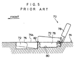
- 61-155242 discloses an example of a conventional seat device in which a seat cushion can be folded forward by a rotating mechanism. This structure is illustrated in Fig. 5 in which the arrow FRONT points toward the front of the vehicle.
- a seat cushion 72 of the seat 70 is rotated approximately 180 degrees toward the front of the vehicle from the position at which the seat cushion 72 is disposed when the seat 70 is in an ordinary state of use (the position illustrated by the solid line), so that the seat cushion 72 is, as illustrated by the two-dot chain line, accommodated in a seat cushion accommodating recess 76 formed in a floor 74.
- a seat back 78 of the seat 70 is rotated toward the front of the vehicle from the position at which the seat back 78 is disposed when the seat 70 is in an ordinary state of use (the position illustrated by the solid line), so as to be accommodated in a seat back accommodating recess 80 formed in the floor 74 as illustrated by the two-dot chain line.
- a substantially flat floor surface 74A is formed at the rear portion of the vehicle.
- the seat cushion 72 in the state illustrated by the two-dot chain line is pulled out from the seat cushion accommodating recess 76 and rotated approximately 180 degrees toward the rear of the vehicle so as to be set in the state illustrated by the solid line.
- the seat back 78 in the state illustrated by the two-dot chain line is pulled out from the seat back accommodating recess 80 and set upright in the state illustrated by the solid line. In this way, the seat 70 is disposed on the floor 74.
- a rotating mechanism 82 for rotating the seat cushion 72 may project from the substantially flat floor surface 74A. Accordingly, when the substantially flat floor surface 74A is used as a bed or the like when the vehicle is stopped, the rotating mechanism 82 may cause an unpleasant sensation.
- an object of the present invention is to provide an alternative vehicle rear seat device in which a rotating mechanism does not project from a flat surface even in cases in which a seat cushion is rotated approximately 180 degrees toward the front of the vehicle from the position at which the seat cushion is disposed when the seat is in an ordinary state of use.
- a first aspect relating to the background of the present invention is a vehicle rear seat device enabling an increase in a floor surface area of a rear portion of a vehicle, comprising a seat cushion provided so as to be rotatable approximately 180 degrees toward a front of the vehicle, a seat back which is forwardly-collapsible, and a rotating mechanism which rotates said seat, wherein a substantially flat surface is formed by a reverse surface of the seat cushion and a reverse surface of the seat back and the rotating mechanism is without projection from the flat surface when the seat cushion is rotated approximately 180 degrees toward the front of the vehicle and the seat back 15 collapsed forward.
- the rotating mechanism does not project from the flat surface.
- the rotating mechanism has an upper plate which is mounted to a front portion of a seat frame provided at the seat cushion upper portion, a lower plate which is mounted to the floor surface, and a hinge shaft which connects the upper plate and the lower plate.
- a second aspect of the present invention is a vehicle rear seat device according to the first aspect of the present invention, wherein a center of rotation of the seat cushion is set at a height which is approximately one-half of a height of the seat cushion at a front end surface of the seat cushion.
- the rotating mechanism does not project from the flat surface.
- a third aspect of the present invention is a vehicle rear seat device in which, in the vehicle rear seat device of the second aspect, at the rotating mechanism, the center of rotation of the seat cushion is set at a height which is approximately one-half of a thickness dimension of the seat back which has been collapsed forward.
- a fourth aspect of the background of the present invention is a vehicle rear seat device in which, in the vehicle rear seat device of the second aspect, the seat cushion has a seat cushion lower portion which is disposed in a floor recess portion formed in a floor surface provided at a rear of the vehicle, and a seat cushion upper portion which is rotatable toward the front of the vehicle, the floor surface being a border between the seat cushion lower portion and the seat cushion upper portion.
- the seat cushion upper portion is superposed on the seat cushion lower portion, and the seating comfort of the rear seat in the ordinary state of use does not deteriorate.
- the seat cushion upper portion is rotated approximately 180 degrees toward the front of the vehicle, the flat surface provided at the reverse surface of the seat cushion upper portion is exposed.
- a fifth aspect of the background of the present invention is a vehicle rear seat device in which, in the fourth aspect, the seat cushion upper portion has a top plate, and a rear end of the top plate is fixed to a rear portion of the seat frame, and a front end of the top plate is allowed to bend toward a bottom of the vehicle when a vehicle passenger is seated, and the front end of the top plate is connected to the lower plate via a connecting member such that bending of the front end of the top plate toward the bottom of the vehicle when the seat cushion is in a folded-forward state is restricted.
- the top plate can withstand local loads such as pressure from a person's hand or the like.
- a sixth aspect of the background of the present invention is a vehicle rear seat device according to the first aspect, in which a rotation axis of the rotating mechanism is without projection from the flat surface.
- the rotating axis does not project from the flat surface.
- a seventh aspect of the background of the present invention is a vehicle rear seat device according to the first aspect, in which a position of the rotation axis in a longitudinal direction and a position of the rotation axis in a vertical direction of the vehicle are without change when the seat cushion is rotated approximately 180 degrees toward the front of the vehicle from a position of the seat cushion during ordinary use.
- At least one of a position of the rotation axis in a longitudinal direction or a position of the rotation axis in a vertical direction of the vehicle does not change when the seat cushion is rotated approximately 180 degrees toward the front of the vehicle from a position of the seat cushion during ordinary use.
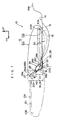
- the arrow FR points toward the front of the vehicle, whereas the arrow UP points toward the top of the vehicle.
- rear seat cushions 12 of left and right side rear seats 10 of the present embodiment are disposed at a floor surface 14A which is a rearward, high portion of a stepped floor 14 of a vehicle.
- the rear seat cushion 12 is formed by a rear seat cushion main body portion 12A, which is a seat cushion upper portion disposed above the floor surface 14A, and a rear seat cushion divisional portion 12B, which is a seat cushion lower portion disposed beneath the floor surface 14A.
- the rear seat cushion main body portion 12A is mounted to the front end portion of the floor surface 14A via rotating mechanisms 18. Due to the rotating mechanisms 18, the rear seat cushion main body portion 12A can be moved to the folded-forward position illustrated by the two-dot chain line in Fig. 4 in which the rear seat cushion main body portion 12A has been rotated approximately 180 degrees toward the front of the vehicle from the position illustrated by the solid line. In this folded-forward state, the rear seat cushion main body portion 12A is supported by, for example, a headrest 15 of the rear seat 10 which is inserted into a headrest stay insertion guide portion provided at the lower portion of a front seat 13 (i.e., at the seat cushion of the front seat 13).
- the rear seat cushion divisional portion 12B remains within a floor recess 16 formed in the floor surface 14A.
- a rear seat back 20 is provided at the rear portion of the rear seat cushion main body portion 12A.
- the rear seat back 20 is mounted so as to be swingable toward the front of the vehicle (i.e., in the direction of arrow A in Fig. 1) by a hinge shaft 19 provided at the vehicle body.
- a reverse surface 20A of the rear seat back 20 becomes substantially flush with a vehicle rear side floor surface 14B which is formed at the vehicle rear side of the floor surface 14A and which is higher than the floor surface 14A. Therefore, a flat floor surface can be provided.
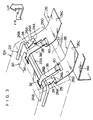
- a pair of the rotating mechanisms 18 is provided at each rear seat, one at the left side of the rear seat and one at the right side.
- Each rotating mechanism 18 is formed by an upper plate 24, a lower plate 26, and a hinge shaft 28.
- the upper plate 24 is mounted to a front portion 22A of a seat frame 22 of the rear seat cushion main body portion 12A.
- the lower plate 26 is mounted to the floor surface 14A.
- the hinge shaft 28 connects a front end portion 24A of the upper plate 24 and front end portions 26A, 26B of the lower plate 26.
- a base portion 26C of the lower plate 26 is fixed by welding or the like to the floor surface 14A. From the front end portion of the base portion 26C of the lower plate 26, an extending portion 26D extends along a front end surface 27 of the rear seat cushion main body portion 12A upwardly at an incline toward the front of the vehicle.
- the front end portions 26A, 26B are formed at the distal end of the extending portion 26D.
- the front end portions 26A, 26B are formed as cylinders which oppose each other with a predetermined interval therebetween and whose axis runs along the vehicle transverse direction.
- the extending portion 26D is set such that a height H1 of the axis of the front end portions 26A, 26B is substantially half of a height H2 of the rear seat cushion main body portion 12A at the front end surface 27 thereof.
- a rear end portion vicinity 24B of the upper plate 24 is fixed by welding or the like to the front portion 22A of the seat frame 22.
- the upper plate 24 extends from the rear end portion vicinity 24B upward at an incline toward the front of the vehicle, and the cylindrical front end portion 24A is formed at the distal end portion thereof.
- the axis of the front end portion 24A runs along the transverse direction of the vehicle.
- the front end portion 24A is inserted between the front end portions 26A, 26B of the lower plate 26, and the hinge shaft 28 is inserted through the front end portion 24A and the front end portions 26A, 26B.
- the rear seat cushion main body portion 12A can be moved to the folded-forward position illustrated by the two-dot chain line in Fig. 1 by rotating the rear seat cushion main body portion 12A by approximately 180 degrees toward the front of the vehicle around the hinge shafts 28 which are set at positions at a height which is substantially half of the height H2 of the rear seat cushion main body portion 12A at the front end surface 27 thereof.
- the rotating mechanisms 18 do not project from the reverse surface of the rear seat cushion main body portion 12A (i.e., the surface of the rear seat cushion main body portion 12A which opposes the floor surface 14A and the rear seat cushion divisional portion 12B when the rear seat 10 is in the ordinary state of use).
- the height H1 of the center of rotation of the rear seat cushion main body portion 12A (i.e., the height of the axis of the front end portions 26A, 26B) is set to substantially half of the thickness dimension W of the upper end surface of the rear seat back 20 which has been collapsed forward (H1 ⁇ W/2).
- a top plate 30 having plasticity is disposed at the bottom portion of the rear seat cushion main body portion 12A.
- the top plate 30 is rectangular, and a rear end portion 30A thereof is mounted to a rear portion 22B of the seat frame 22.
- elongated holes 32, 34 which extend in the transverse direction of the vehicle are formed at the left and right sides of a vicinity of the front end portion of the top plate 30.
- Ones of end portions of webbings 36, 38, which serve as connecting members, are connected to the elongated holes 32, 34, respectively.
- the other end portions of the webbings 36, 38 are connected to elongated holes 40 which extend in the transverse direction of the vehicle and are formed in the extending portions 26D of the lower plates 26.
- the elongated holes 40 are formed at positions which are slightly beneath the hinge shafts 28, i.e., positions which are slightly lower than the height H1 which is substantially half of the height H2 of the rear seat cushion main body portion 12A.
- the webbings 36, 38 are disposed at the seat outer side of the seat frame 22. For example, when the rear seat cushion main body portion 12A is in an ordinary state of use (the state illustrated in Fig. 2 and by the solid line in Fig. 1), the webbings 36, 38 pass beneath the front portion 22A of the seat frame 22.
- the top plate 30 can bend downward, as illustrated by the one-dot chain line in Fig. 1, together with the rear seat cushion main body portion 12A in accordance with the body type and the weight of the passenger seated on the seat.
- a seat surface covering 31 also bends downward as illustrated by the two-dot chain line in Fig. 1.
- the elongated holes 40 of the lower plates 26 are set at positions slightly lower than the hinge shafts 28. Therefore, when the rear seat cushion main body portion 12A is moved to the folded-forward position at which the rear seat cushion main body portion 12A is rotated approximately 180 degrees toward the front of the vehicle around the hinge shafts 28, the distance between, on the one hand, the elongated holes 32, 34 of the top plate 30 and, on the other hand, the elongated holes 40 of the lower plates 26 is longer than when the rear seat cushion main body portion 12A is in the ordinary state of use (the state illustrated in Fig. 2). Further, the intermediate portions of the webbings 36, 38 are pushed substantially upward and rearward (i.e., in the direction of arrow B in Fig.
- the front portion 22A of the seat frame 22 As a result, tension is generated in the webbings 36, 38.
- the length of the webbings 36, 38 is set to a length at which, due to this tension, the upper plate 30 forms a flat, difficult-to-bend surface which can withstand local loads such pressure from a person's hand or the like. Further, the top plate 30 is not fixed to the seat frame 20 in the vehicle transverse direction.
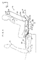
- the rear seat cushion main body portion 12A is rotated approximately 180 degrees toward the front of the vehicle around the hinge shafts 28 of the rotating mechanisms 18 which are set in a vicinity of the center of the height H2 of the rear seat cushion main body portion 12A at the front end surface 27 thereof.
- the rear seat cushion main body portion 12A can be moved to the folded-forward position illustrated by the two-dot chain line in Fig. 1.
- the rear seat back 20 and the rear seat cushion main body portion 12A are made flat, as illustrated by Fig.
- the rotating mechanisms 18 do not project from the reverse surface of the rear seat cushion main body portion 12A because vicinities of the hinge shafts 28 of the rotating mechanisms 18 are interposed, without any gaps, between the rear seat back 20 and the rear seat cushion main body portion 12A which have been made flat. Accordingly, when the vehicle is stopped, even if the rear seat back 20 and the rear seat cushion main body portion 12A which have been made flat are used as a bed or the like, the rotating mechanisms 18 hardly cause any unpleasant sensations.
- the height H1 of the center of rotation of the rear seat cushion main body portion 12A is set to be approximately half of the thickness dimension W of the rear seat back 20 which has been collapsed forward (H ⁇ W/2). Therefore, when the rear seat cushion main body portion 12A is rotated approximately 180 degrees toward the front of the vehicle by the rotating mechanisms 18 and the rear seat back 20 is collapsed forward, a flat surface which is flush from the reverse surface of the rear seat cushion main body portion 12A to the reverse surface 20A of the rear seat back 20 can be ensured.
- the top plate 30, together with the rear seat cushion main body portion 12A bends downwardly as shown by the one-dot chain line in Fig. 1 in accordance with the body type and the weight of the passenger seated on the seat. As a result, the seating comfort of the seat does not deteriorate.
- the distance between, on the one hand, the elongated holes 32, 34 of the top plate 30, and on the other hand, the elongated holes 40 of the lower plates 26, is longer than in a case in which the rear seat cushion main body portion 12A is in the ordinary state of use as illustrated in Fig. 2.
- intermediate portions of the webbings 36, 38 are pushed substantially upwardly and rearwardly (in the direction of arrow B in Fig. 1) by the front portion 22A of the seat frame 22.
- tension is generated in the webbings 36, 38, and the downward bending of the top plate 30 is restricted.
- the top plate 30 of the rear seat cushion main body portion 12A which is at the folded-forward position can withstand local loads of an extent such as pressure from a person's hand or the like.
- the rear seat cushion main body portion 12A when the seat is in the ordinary state of use, the rear seat cushion main body portion 12A is superposed on the rear seat cushion divisional portion 12B, and the seating comfort of the rear seat 10 does not deteriorate.
- the rear seat cushion main body portion 12A When the rear seat cushion main body portion 12A is at the folded-forward position, the rear seat cushion divisional portion 12B remains in the floor recess 16 formed in the floor surface 14A, and the reverse surface of the rear seat cushion main body portion 12A forms a flat surface.
- webbings 36, 38 are used as the connecting members in the vehicle rear seat device of the present embodiment.
- the connecting members are not limited to webbings, and other members such as wires, rubber belts or the like may be used.
Landscapes
- Engineering & Computer Science (AREA)
- Aviation & Aerospace Engineering (AREA)
- Transportation (AREA)
- Mechanical Engineering (AREA)
- Seats For Vehicles (AREA)
Description
Claims (11)
- A vehicle rear seat device enabling the provision of a substantially flat floor surface at a rear portion of a vehicle, comprising:wherein the substantially flat surface is formed by a reverse surface of said seat cushion (12) and a reverse surface of said seat back (20) and said rotating mechanism (18) is without projection from said flat surface when said seat cushion (12) is rotated approximately 180 degrees toward the front of the vehicle and said seat back (20) is collapsed forward,a seat cushion (12) provided so as to be rotatable approximately 180 degrees toward a front of the vehicle;a seat back (20) which is forwardly-collapsible; anda rotating mechanism (18, 19) which rotates said seat
characterized in that
said rotating mechanism (18) has an upper plate (24) which is mounted to a front portion of said sent cushion (12), a lower plate (26) which is mounted to the front portion of a floor surface (14A) provided at a rear of the vehicle, and a hinge shaft (28) which connects said upper plate (24) and said lower plate (26). - A vehicle rear seat device according to claim 1, wherein a rotation axis of said rotating mechanism (18) is without projection from said flat surface.
- A vehicle rear seat device according to claim 2, wherein a position of said rotation axis in a longitudinal direction and a position of said rotation axis in a vertical direction of the vehicle are without change when said seat cushion (12) is rotated approximately 180 degrees toward the front of the vehicle from a position of said seat cushion (12) during ordinary use.
- A vehicle rear seat device according to one of the preceding claims, wherein a center of rotation of said seat cushion (12) is set at a height which is approximately one-half of a height of said seat cushion (12) at a front end surface of said seat cushion (12).
- A vehicle rear seat device according to claim 4, wherein at said rotating mechanism (18), the center of rotation of said seat cushion (12) is set at a height which is approximately one-half of a thickness dimension of said seat back (20) which has been collapsed forward.
- A vehicle rear seat device according to claim 4 or 5, wherein said seat cushion (12) has a seat cushion lower portion (12B) which is disposed in a floor recess portion (16) formed in the floor surface (14A), and a seat cushion upper portion (12A) which is rotatable toward the front of the vehicle, said seat cushion lower portion being disposed beneath the floor surface (14A) and said seat cushion upper portion being disposed above the floor surface (14A) in an ordinary state of use.
- A vehicle rear seat device according to claim 6, wherein the upper plate (24) is mounted to a front portion of a seat frame (22) provided at said seat cushion upper portion.
- A vehicle rear seat device according to claim 7, wherein said seat cushion upper portion (12A) has a top plate (30), and a rear end (30A) of said top plate is fixed to a rear portion (22B) of the seat frame (22), and a front end of said top plate (30) is allowed to bend toward a bottom of the vehicle when a vehicle passenger is seated, and the front end of said top plate (30) is connected to said lower plate (26) via a connecting member (36, 38) such that bending of the front end of said top plate (30) toward the bottom of the vehicle when said seat cushion (12) is in a folded-forward state is restricted.
- A vehicle rear seat device according to claim 8, wherein said connecting member (36, 38) is provided beneath a front portion of the seat frame (22) when a vehicle passenger is seated.
- A vehicle rear seat device according to claim 8, wherein when said seat cushion (12) is in a folded-forward state, a substantially intermediate portion of said connecting member (36, 38) is pushed by the front portion (22A) of the seat frame (22) such that tension is applied to said connecting member.
- A vehicle rear seat device according to claim 8, 9 or 10, wherein said connecting member (36, 38) is an elongated member.
Applications Claiming Priority (3)
| Application Number | Priority Date | Filing Date | Title |
|---|---|---|---|
| JP07333449A JP3136976B2 (en) | 1995-12-21 | 1995-12-21 | Rear seat device for vehicles |
| JP333449/95 | 1995-12-21 | ||
| JP33344995 | 1995-12-21 |
Publications (3)
| Publication Number | Publication Date |
|---|---|
| EP0780261A2 EP0780261A2 (en) | 1997-06-25 |
| EP0780261A3 EP0780261A3 (en) | 1998-09-02 |
| EP0780261B1 true EP0780261B1 (en) | 2002-07-31 |
Family
ID=18266222
Family Applications (1)
| Application Number | Title | Priority Date | Filing Date |
|---|---|---|---|
| EP96119646A Expired - Lifetime EP0780261B1 (en) | 1995-12-21 | 1996-12-06 | Vehicle rear seat device |
Country Status (4)
| Country | Link |
|---|---|
| US (1) | US5730496A (en) |
| EP (1) | EP0780261B1 (en) |
| JP (1) | JP3136976B2 (en) |
| DE (1) | DE69622675T2 (en) |
Families Citing this family (21)
| Publication number | Priority date | Publication date | Assignee | Title |
|---|---|---|---|---|
| JP3521108B2 (en) * | 1997-03-27 | 2004-04-19 | テイ・エス テック株式会社 | Car foldable seat |
| JP3539228B2 (en) * | 1997-10-23 | 2004-07-07 | トヨタ車体株式会社 | Vehicle folding seat |
| US5904404A (en) * | 1997-11-18 | 1999-05-18 | Lear Corporation | Latch assist mechanism for a foldable automotive seat |
| US5961183A (en) * | 1998-03-25 | 1999-10-05 | General Motors Corporation | Tumble forward seat with automatic seat adjuster return |
| US6183033B1 (en) * | 1998-03-31 | 2001-02-06 | Ikeda Bussan Co., Ltd. | Automobile seat |
| DE19825571C1 (en) * | 1998-06-08 | 2000-01-27 | Faure Bertrand Sitztech Gmbh | Rear seat for motor vehicle |
| DE19837838C1 (en) * | 1998-08-20 | 1999-11-18 | Daimler Chrysler Ag | Rear seat for motor vehicle |
| DE19841363C1 (en) * | 1998-09-10 | 2000-04-20 | Opel Adam Ag | Motor vehicle rear seat with foldable backrest and lowerable seat part |
| US6113191A (en) * | 1998-10-21 | 2000-09-05 | Johnson Controls Technology Company | Storable seat assembly |
| DE19902966C1 (en) * | 1999-01-26 | 2000-04-20 | Faure Bertrand Sitztech Gmbh | Seat row for motor vehicle has middle auxiliary seat forming load support panel when retracted |
| DE19904009C1 (en) * | 1999-02-02 | 2000-05-31 | Faure Bertrand Sitztech Gmbh | Back seat for motor vehicle has two independent guide rod systems to move seat from rear use position into forward lowered position to create load area |
| DE19911015C1 (en) * | 1999-03-12 | 1999-12-16 | Faure Bertrand Sitztech Gmbh | Seat for motor vehicle |
| GB2356557B (en) | 1999-11-26 | 2003-12-17 | Autoliv Dev | Improvements in or relating to a vehicle seat unit |
| DE19957380C1 (en) * | 1999-11-29 | 2001-03-01 | Faure Bertrand Sitztech Gmbh | Automobile rear passenger seat with fold-down backrest has support lever at front of seat squab released automatically when backrest is folded forwards |
| US6874667B2 (en) * | 1999-11-30 | 2005-04-05 | Johnson Controls Technology Company | Vehicle cargo management system |
| US6499787B2 (en) | 2000-07-26 | 2002-12-31 | Lear Corporation | Collapsible vehicle seat assemblies |
| DE10054825C1 (en) * | 2000-11-04 | 2001-07-26 | Faurecia Autositze Gmbh & Co | Middle seat for vehicle, locked by lock on one part of seat with rear end mounted on bottom of vehicle by eccentric bush on turning axis of rear pivot |
| DE10146711A1 (en) | 2001-09-21 | 2003-04-24 | Intier Automotive Seating Germ | Motor vehicle rear seat |
| FR2841836B1 (en) * | 2002-07-04 | 2004-09-10 | Faurecia Sieges Automobile | MOTOR VEHICLE SEAT |
| KR20040013804A (en) * | 2002-08-08 | 2004-02-14 | 현대자동차주식회사 | Construction for the lower anchor of a back seat frame for mounting a child seat |
| FR2846919A1 (en) * | 2002-11-07 | 2004-05-14 | Faurecia Sieges Automobile | Back seat arrangement for automobile vehicle, has seat part facing headrest, vehicle floor zone facing reduced thickness part of seat, and complementary portion of cushioning placed to floor |
Citations (1)
| Publication number | Priority date | Publication date | Assignee | Title |
|---|---|---|---|---|
| EP0013849A2 (en) * | 1979-01-29 | 1980-08-06 | Automobiles Peugeot | Improvements to convertible seats for vehicles |
Family Cites Families (13)
| Publication number | Priority date | Publication date | Assignee | Title |
|---|---|---|---|---|
| FR1427847A (en) * | 1964-12-22 | 1966-02-11 | Simca Automobiles Sa | Convertible rear compartment of motor vehicle |
| US4133556A (en) * | 1977-07-18 | 1979-01-09 | General Motors Corporation | Seat belt positioning device |
| FR2420445A1 (en) * | 1978-03-20 | 1979-10-19 | Peugeot | TRANSFORMABLE SEAT FOR MOTOR VEHICLE |
| SE421893B (en) * | 1980-02-15 | 1982-02-08 | Volvo Ab | HEAD PROTECTOR FOR THE BACKGROUND IN COMBIBILAR PROVIDED ON A FRAME Foldable Backrest |
| SE8202022L (en) * | 1982-03-30 | 1983-10-01 | Saab Scania Ab | DEVICE FOR REVERSION OF THE VEHICLE SEAT |
| JPS5994934A (en) * | 1982-09-30 | 1984-05-31 | ゼロツクス・コ−ポレ−シヨン | Computer network for receiving line fiber optic type local district capable of monitoring simultaneously upon transmitting |
| JPS5994933A (en) * | 1982-11-20 | 1984-05-31 | Hitachi Kiden Kogyo Ltd | Communication device between fixed station and terminal station utilizing optical beam |
| JPS61155242A (en) * | 1984-12-26 | 1986-07-14 | 大阪セメント株式会社 | Water-resistant fluoric anhydrous gypsum composition |
| JPS61113138U (en) * | 1984-12-28 | 1986-07-17 | ||
| FR2577860B1 (en) * | 1985-02-27 | 1987-04-10 | Renault | TRANSFORMABLE SEAT FOR MOTOR VEHICLE |
| JPS61155242U (en) | 1985-03-20 | 1986-09-26 | ||
| JPH054429Y2 (en) * | 1987-03-30 | 1993-02-03 | ||
| DE19518393C2 (en) * | 1995-05-19 | 1996-06-20 | Audi Ag | Motor vehicle |
-
1995
- 1995-12-21 JP JP07333449A patent/JP3136976B2/en not_active Expired - Fee Related
-
1996
- 1996-12-06 EP EP96119646A patent/EP0780261B1/en not_active Expired - Lifetime
- 1996-12-06 DE DE69622675T patent/DE69622675T2/en not_active Expired - Lifetime
- 1996-12-11 US US08/764,626 patent/US5730496A/en not_active Expired - Lifetime
Patent Citations (1)
| Publication number | Priority date | Publication date | Assignee | Title |
|---|---|---|---|---|
| EP0013849A2 (en) * | 1979-01-29 | 1980-08-06 | Automobiles Peugeot | Improvements to convertible seats for vehicles |
Also Published As
| Publication number | Publication date |
|---|---|
| EP0780261A2 (en) | 1997-06-25 |
| US5730496A (en) | 1998-03-24 |
| DE69622675D1 (en) | 2002-09-05 |
| DE69622675T2 (en) | 2003-04-03 |
| EP0780261A3 (en) | 1998-09-02 |
| JPH09169231A (en) | 1997-06-30 |
| JP3136976B2 (en) | 2001-02-19 |
Similar Documents
| Publication | Publication Date | Title |
|---|---|---|
| EP0780261B1 (en) | Vehicle rear seat device | |
| CN104527479A (en) | Vehicle seat | |
| JP3360556B2 (en) | Vehicle seat | |
| JP3201592B2 (en) | Vehicle seat | |
| JPH1134707A (en) | Vehicular seat | |
| US5971466A (en) | Rear seat apparatus for a vehicle | |
| JPS6157435A (en) | Bucket beat | |
| JPH09254689A (en) | Frame of forwardly foldable seat back of automotive seat | |
| JP2549114Y2 (en) | Bench-type automotive seat frame structure | |
| JP3738102B2 (en) | Car backseat | |
| JP3137381B2 (en) | Car seat slide structure | |
| JP2857158B2 (en) | Seat back frame | |
| JP2764642B2 (en) | Seat cushion frame structure | |
| JP3736759B2 (en) | The structure of the center occupant seat of the three-seat rear seat | |
| JP4114026B2 (en) | Sheet folding structure | |
| KR200147457Y1 (en) | Haedrest connecting device for a car | |
| JP3346714B2 (en) | Automotive seat structure | |
| JP2534832Y2 (en) | Submersion prevention mechanism for vehicle seats | |
| JP3146544B2 (en) | Cab-over type car seat structure | |
| JPH11189175A (en) | Floor structure for automobile | |
| JP2000189276A (en) | Seat cushion for vehicle | |
| JP3531476B2 (en) | Car body floor structure | |
| JP3268417B2 (en) | Automotive seats and passenger cars equipped with these seats | |
| JP3299325B2 (en) | Seats for children and vehicles | |
| JPS6040341Y2 (en) | Front seat device for cab-over type cars |
Legal Events
| Date | Code | Title | Description |
|---|---|---|---|
| PUAI | Public reference made under article 153(3) epc to a published international application that has entered the european phase |
Free format text: ORIGINAL CODE: 0009012 |
|
| 17P | Request for examination filed |
Effective date: 19961220 |
|
| AK | Designated contracting states |
Kind code of ref document: A2 Designated state(s): DE FR GB |
|
| PUAL | Search report despatched |
Free format text: ORIGINAL CODE: 0009013 |
|
| AK | Designated contracting states |
Kind code of ref document: A3 Designated state(s): DE FR GB |
|
| 17Q | First examination report despatched |
Effective date: 20000727 |
|
| GRAG | Despatch of communication of intention to grant |
Free format text: ORIGINAL CODE: EPIDOS AGRA |
|
| GRAG | Despatch of communication of intention to grant |
Free format text: ORIGINAL CODE: EPIDOS AGRA |
|
| GRAH | Despatch of communication of intention to grant a patent |
Free format text: ORIGINAL CODE: EPIDOS IGRA |
|
| GRAH | Despatch of communication of intention to grant a patent |
Free format text: ORIGINAL CODE: EPIDOS IGRA |
|
| GRAA | (expected) grant |
Free format text: ORIGINAL CODE: 0009210 |
|
| AK | Designated contracting states |
Kind code of ref document: B1 Designated state(s): DE FR GB |
|
| REG | Reference to a national code |
Ref country code: GB Ref legal event code: FG4D |
|
| REF | Corresponds to: |
Ref document number: 69622675 Country of ref document: DE Date of ref document: 20020905 |
|
| ET | Fr: translation filed | ||
| PLBE | No opposition filed within time limit |
Free format text: ORIGINAL CODE: 0009261 |
|
| STAA | Information on the status of an ep patent application or granted ep patent |
Free format text: STATUS: NO OPPOSITION FILED WITHIN TIME LIMIT |
|
| 26N | No opposition filed |
Effective date: 20030506 |
|
| PGFP | Annual fee paid to national office [announced via postgrant information from national office to epo] |
Ref country code: GB Payment date: 20031203 Year of fee payment: 8 |
|
| PG25 | Lapsed in a contracting state [announced via postgrant information from national office to epo] |
Ref country code: GB Free format text: LAPSE BECAUSE OF NON-PAYMENT OF DUE FEES Effective date: 20041206 |
|
| GBPC | Gb: european patent ceased through non-payment of renewal fee |
Effective date: 20041206 |
|
| REG | Reference to a national code |
Ref country code: FR Ref legal event code: D6 |
|
| PGFP | Annual fee paid to national office [announced via postgrant information from national office to epo] |
Ref country code: FR Payment date: 20091221 Year of fee payment: 14 |
|
| PGFP | Annual fee paid to national office [announced via postgrant information from national office to epo] |
Ref country code: DE Payment date: 20091203 Year of fee payment: 14 |
|
| REG | Reference to a national code |
Ref country code: FR Ref legal event code: ST Effective date: 20110831 |
|
| PG25 | Lapsed in a contracting state [announced via postgrant information from national office to epo] |
Ref country code: FR Free format text: LAPSE BECAUSE OF NON-PAYMENT OF DUE FEES Effective date: 20110103 |
|
| PG25 | Lapsed in a contracting state [announced via postgrant information from national office to epo] |
Ref country code: DE Free format text: LAPSE BECAUSE OF NON-PAYMENT OF DUE FEES Effective date: 20110701 |
|
| REG | Reference to a national code |
Ref country code: DE Ref legal event code: R119 Ref document number: 69622675 Country of ref document: DE Effective date: 20110701 |