EP0779122A2 - Werkstückdrehtisch - Google Patents
Werkstückdrehtisch Download PDFInfo
- Publication number
- EP0779122A2 EP0779122A2 EP19960309075 EP96309075A EP0779122A2 EP 0779122 A2 EP0779122 A2 EP 0779122A2 EP 19960309075 EP19960309075 EP 19960309075 EP 96309075 A EP96309075 A EP 96309075A EP 0779122 A2 EP0779122 A2 EP 0779122A2
- Authority
- EP
- European Patent Office
- Prior art keywords
- detent
- base
- locking
- spring
- miter saw
- Prior art date
- Legal status (The legal status is an assumption and is not a legal conclusion. Google has not performed a legal analysis and makes no representation as to the accuracy of the status listed.)
- Granted
Links
Images


Classifications
-
- B—PERFORMING OPERATIONS; TRANSPORTING
- B23—MACHINE TOOLS; METAL-WORKING NOT OTHERWISE PROVIDED FOR
- B23D—PLANING; SLOTTING; SHEARING; BROACHING; SAWING; FILING; SCRAPING; LIKE OPERATIONS FOR WORKING METAL BY REMOVING MATERIAL, NOT OTHERWISE PROVIDED FOR
- B23D45/00—Sawing machines or sawing devices with circular saw blades or with friction saw discs
- B23D45/04—Sawing machines or sawing devices with circular saw blades or with friction saw discs with a circular saw blade or the stock carried by a pivoted lever
- B23D45/042—Sawing machines or sawing devices with circular saw blades or with friction saw discs with a circular saw blade or the stock carried by a pivoted lever with the saw blade carried by a pivoted lever
- B23D45/046—Sawing machines or sawing devices with circular saw blades or with friction saw discs with a circular saw blade or the stock carried by a pivoted lever with the saw blade carried by a pivoted lever the pivoted lever being mounted on a carriage
- B23D45/048—Sawing machines or sawing devices with circular saw blades or with friction saw discs with a circular saw blade or the stock carried by a pivoted lever with the saw blade carried by a pivoted lever the pivoted lever being mounted on a carriage the saw blade being adjustable according to angle of cut
-
- B—PERFORMING OPERATIONS; TRANSPORTING
- B23—MACHINE TOOLS; METAL-WORKING NOT OTHERWISE PROVIDED FOR
- B23D—PLANING; SLOTTING; SHEARING; BROACHING; SAWING; FILING; SCRAPING; LIKE OPERATIONS FOR WORKING METAL BY REMOVING MATERIAL, NOT OTHERWISE PROVIDED FOR
- B23D45/00—Sawing machines or sawing devices with circular saw blades or with friction saw discs
- B23D45/04—Sawing machines or sawing devices with circular saw blades or with friction saw discs with a circular saw blade or the stock carried by a pivoted lever
- B23D45/042—Sawing machines or sawing devices with circular saw blades or with friction saw discs with a circular saw blade or the stock carried by a pivoted lever with the saw blade carried by a pivoted lever
- B23D45/044—Sawing machines or sawing devices with circular saw blades or with friction saw discs with a circular saw blade or the stock carried by a pivoted lever with the saw blade carried by a pivoted lever the saw blade being adjustable according to angle of cut
-
- B—PERFORMING OPERATIONS; TRANSPORTING
- B23—MACHINE TOOLS; METAL-WORKING NOT OTHERWISE PROVIDED FOR
- B23D—PLANING; SLOTTING; SHEARING; BROACHING; SAWING; FILING; SCRAPING; LIKE OPERATIONS FOR WORKING METAL BY REMOVING MATERIAL, NOT OTHERWISE PROVIDED FOR
- B23D47/00—Sawing machines or sawing devices working with circular saw blades, characterised only by constructional features of particular parts
- B23D47/02—Sawing machines or sawing devices working with circular saw blades, characterised only by constructional features of particular parts of frames; of guiding arrangements for work-table or saw-carrier
- B23D47/025—Sawing machines or sawing devices working with circular saw blades, characterised only by constructional features of particular parts of frames; of guiding arrangements for work-table or saw-carrier of tables
-
- B—PERFORMING OPERATIONS; TRANSPORTING
- B23—MACHINE TOOLS; METAL-WORKING NOT OTHERWISE PROVIDED FOR
- B23Q—DETAILS, COMPONENTS, OR ACCESSORIES FOR MACHINE TOOLS, e.g. ARRANGEMENTS FOR COPYING OR CONTROLLING; MACHINE TOOLS IN GENERAL CHARACTERISED BY THE CONSTRUCTION OF PARTICULAR DETAILS OR COMPONENTS; COMBINATIONS OR ASSOCIATIONS OF METAL-WORKING MACHINES, NOT DIRECTED TO A PARTICULAR RESULT
- B23Q1/00—Members which are comprised in the general build-up of a form of machine, particularly relatively large fixed members
- B23Q1/25—Movable or adjustable work or tool supports
- B23Q1/26—Movable or adjustable work or tool supports characterised by constructional features relating to the co-operation of relatively movable members; Means for preventing relative movement of such members
- B23Q1/262—Movable or adjustable work or tool supports characterised by constructional features relating to the co-operation of relatively movable members; Means for preventing relative movement of such members with means to adjust the distance between the relatively slidable members
- B23Q1/265—Movable or adjustable work or tool supports characterised by constructional features relating to the co-operation of relatively movable members; Means for preventing relative movement of such members with means to adjust the distance between the relatively slidable members between rotating members
-
- B—PERFORMING OPERATIONS; TRANSPORTING
- B23—MACHINE TOOLS; METAL-WORKING NOT OTHERWISE PROVIDED FOR
- B23Q—DETAILS, COMPONENTS, OR ACCESSORIES FOR MACHINE TOOLS, e.g. ARRANGEMENTS FOR COPYING OR CONTROLLING; MACHINE TOOLS IN GENERAL CHARACTERISED BY THE CONSTRUCTION OF PARTICULAR DETAILS OR COMPONENTS; COMBINATIONS OR ASSOCIATIONS OF METAL-WORKING MACHINES, NOT DIRECTED TO A PARTICULAR RESULT
- B23Q1/00—Members which are comprised in the general build-up of a form of machine, particularly relatively large fixed members
- B23Q1/25—Movable or adjustable work or tool supports
- B23Q1/26—Movable or adjustable work or tool supports characterised by constructional features relating to the co-operation of relatively movable members; Means for preventing relative movement of such members
- B23Q1/28—Means for securing sliding members in any desired position
-
- B—PERFORMING OPERATIONS; TRANSPORTING
- B27—WORKING OR PRESERVING WOOD OR SIMILAR MATERIAL; NAILING OR STAPLING MACHINES IN GENERAL
- B27B—SAWS FOR WOOD OR SIMILAR MATERIAL; COMPONENTS OR ACCESSORIES THEREFOR
- B27B5/00—Sawing machines working with circular or cylindrical saw blades; Components or equipment therefor
- B27B5/29—Details; Component parts; Accessories
-
- Y—GENERAL TAGGING OF NEW TECHNOLOGICAL DEVELOPMENTS; GENERAL TAGGING OF CROSS-SECTIONAL TECHNOLOGIES SPANNING OVER SEVERAL SECTIONS OF THE IPC; TECHNICAL SUBJECTS COVERED BY FORMER USPC CROSS-REFERENCE ART COLLECTIONS [XRACs] AND DIGESTS
- Y10—TECHNICAL SUBJECTS COVERED BY FORMER USPC
- Y10T—TECHNICAL SUBJECTS COVERED BY FORMER US CLASSIFICATION
- Y10T409/00—Gear cutting, milling, or planing
- Y10T409/30—Milling
- Y10T409/30868—Work support
- Y10T409/30896—Work support with angular adjustment
-
- Y—GENERAL TAGGING OF NEW TECHNOLOGICAL DEVELOPMENTS; GENERAL TAGGING OF CROSS-SECTIONAL TECHNOLOGIES SPANNING OVER SEVERAL SECTIONS OF THE IPC; TECHNICAL SUBJECTS COVERED BY FORMER USPC CROSS-REFERENCE ART COLLECTIONS [XRACs] AND DIGESTS
- Y10—TECHNICAL SUBJECTS COVERED BY FORMER USPC
- Y10T—TECHNICAL SUBJECTS COVERED BY FORMER US CLASSIFICATION
- Y10T83/00—Cutting
- Y10T83/748—With work immobilizer
- Y10T83/7593—Work-stop abutment
- Y10T83/764—Retractable
-
- Y—GENERAL TAGGING OF NEW TECHNOLOGICAL DEVELOPMENTS; GENERAL TAGGING OF CROSS-SECTIONAL TECHNOLOGIES SPANNING OVER SEVERAL SECTIONS OF THE IPC; TECHNICAL SUBJECTS COVERED BY FORMER USPC CROSS-REFERENCE ART COLLECTIONS [XRACs] AND DIGESTS
- Y10—TECHNICAL SUBJECTS COVERED BY FORMER USPC
- Y10T—TECHNICAL SUBJECTS COVERED BY FORMER US CLASSIFICATION
- Y10T83/00—Cutting
- Y10T83/748—With work immobilizer
- Y10T83/7593—Work-stop abutment
- Y10T83/7647—Adjustable
-
- Y—GENERAL TAGGING OF NEW TECHNOLOGICAL DEVELOPMENTS; GENERAL TAGGING OF CROSS-SECTIONAL TECHNOLOGIES SPANNING OVER SEVERAL SECTIONS OF THE IPC; TECHNICAL SUBJECTS COVERED BY FORMER USPC CROSS-REFERENCE ART COLLECTIONS [XRACs] AND DIGESTS
- Y10—TECHNICAL SUBJECTS COVERED BY FORMER USPC
- Y10T—TECHNICAL SUBJECTS COVERED BY FORMER US CLASSIFICATION
- Y10T83/00—Cutting
- Y10T83/768—Rotatable disc tool pair or tool and carrier
- Y10T83/7684—With means to support work relative to tool[s]
- Y10T83/7693—Tool moved relative to work-support during cutting
- Y10T83/7697—Tool angularly adjustable relative to work-support
-
- Y—GENERAL TAGGING OF NEW TECHNOLOGICAL DEVELOPMENTS; GENERAL TAGGING OF CROSS-SECTIONAL TECHNOLOGIES SPANNING OVER SEVERAL SECTIONS OF THE IPC; TECHNICAL SUBJECTS COVERED BY FORMER USPC CROSS-REFERENCE ART COLLECTIONS [XRACs] AND DIGESTS
- Y10—TECHNICAL SUBJECTS COVERED BY FORMER USPC
- Y10T—TECHNICAL SUBJECTS COVERED BY FORMER US CLASSIFICATION
- Y10T83/00—Cutting
- Y10T83/768—Rotatable disc tool pair or tool and carrier
- Y10T83/7684—With means to support work relative to tool[s]
- Y10T83/7701—Supporting surface and tool axis angularly related
- Y10T83/7705—Adjustable angular relationship
-
- Y—GENERAL TAGGING OF NEW TECHNOLOGICAL DEVELOPMENTS; GENERAL TAGGING OF CROSS-SECTIONAL TECHNOLOGIES SPANNING OVER SEVERAL SECTIONS OF THE IPC; TECHNICAL SUBJECTS COVERED BY FORMER USPC CROSS-REFERENCE ART COLLECTIONS [XRACs] AND DIGESTS
- Y10—TECHNICAL SUBJECTS COVERED BY FORMER USPC
- Y10T—TECHNICAL SUBJECTS COVERED BY FORMER US CLASSIFICATION
- Y10T83/00—Cutting
- Y10T83/768—Rotatable disc tool pair or tool and carrier
- Y10T83/7684—With means to support work relative to tool[s]
- Y10T83/7722—Support and tool relatively adjustable
- Y10T83/7726—By movement of the tool
-
- Y—GENERAL TAGGING OF NEW TECHNOLOGICAL DEVELOPMENTS; GENERAL TAGGING OF CROSS-SECTIONAL TECHNOLOGIES SPANNING OVER SEVERAL SECTIONS OF THE IPC; TECHNICAL SUBJECTS COVERED BY FORMER USPC CROSS-REFERENCE ART COLLECTIONS [XRACs] AND DIGESTS
- Y10—TECHNICAL SUBJECTS COVERED BY FORMER USPC
- Y10T—TECHNICAL SUBJECTS COVERED BY FORMER US CLASSIFICATION
- Y10T83/00—Cutting
- Y10T83/768—Rotatable disc tool pair or tool and carrier
- Y10T83/7755—Carrier for rotatable tool movable during cutting
- Y10T83/7763—Tool carrier reciprocable rectilinearly
- Y10T83/7768—With means to adjust path of reciprocation
- Y10T83/7772—Angular relative to previous path
-
- Y—GENERAL TAGGING OF NEW TECHNOLOGICAL DEVELOPMENTS; GENERAL TAGGING OF CROSS-SECTIONAL TECHNOLOGIES SPANNING OVER SEVERAL SECTIONS OF THE IPC; TECHNICAL SUBJECTS COVERED BY FORMER USPC CROSS-REFERENCE ART COLLECTIONS [XRACs] AND DIGESTS
- Y10—TECHNICAL SUBJECTS COVERED BY FORMER USPC
- Y10T—TECHNICAL SUBJECTS COVERED BY FORMER US CLASSIFICATION
- Y10T83/00—Cutting
- Y10T83/768—Rotatable disc tool pair or tool and carrier
- Y10T83/7755—Carrier for rotatable tool movable during cutting
- Y10T83/7788—Tool carrier oscillated or rotated
-
- Y—GENERAL TAGGING OF NEW TECHNOLOGICAL DEVELOPMENTS; GENERAL TAGGING OF CROSS-SECTIONAL TECHNOLOGIES SPANNING OVER SEVERAL SECTIONS OF THE IPC; TECHNICAL SUBJECTS COVERED BY FORMER USPC CROSS-REFERENCE ART COLLECTIONS [XRACs] AND DIGESTS
- Y10—TECHNICAL SUBJECTS COVERED BY FORMER USPC
- Y10T—TECHNICAL SUBJECTS COVERED BY FORMER US CLASSIFICATION
- Y10T83/00—Cutting
- Y10T83/869—Means to drive or to guide tool
- Y10T83/8773—Bevel or miter cut
Definitions
- the present invention relates to a compound miter saw or other power operated equipment or machinery utilising a cutter for performing working operations on a workpiece. More particularly, the present invention relates to improvements in the table assembly for the miter adjustment for such power operated equipment.
- the table assembly includes a three position locking mechanism and a set of orientated wear plates.
- Saws and other apparatus designed for cutting or performing other working operations on a workpiece typically require adjustment mechanisms for moving the saw blade or cutting tool into an angular relationship to the workpiece.
- Such equipment include cross-cut compound miter saws which are adapted for allowing the user selectively to move the saw blade into any of a number of positions or modes for square cutting, miter cutting, bevel cutting, or compound miter cutting where a combination miter and bevel are cut.
- some operations, such as dado cutting or shaping operations require the use of saw blades or other cutting or working devices of different shapes or sizes to be substituted for one another in order to perform the desired operation on the workpiece, whether the workpiece is composed of wood, plastic, metal or other materials.
- the saw blade, cutter or other working device is angularly adjustable with respect to a horizontal base and a vertical fence against which the workpiece is positioned.
- the miter adjustment allows the saw blade, cutter or other working device to move angularly with respect to the vertical fence while maintaining perpendicularity with the horizontal base.
- the bevel adjustment allows the saw blade, cutter or other working device to move angularly with respect to the horizontal base while maintaining perpendicularity with the vertical fence. At times it may be desirable to cut a combination miter and bevel by simultaneously adjusting the angularity of the blade with respect to both the horizontal base and the vertical fence.
- locking mechanisms for the miter and bevel adjustment must be activated in order to prohibit movement of the saw blade, cutter or other working device with respect to the base and fence while the cutting operation is performed.
- These locking mechanisms need to be easily activated, adjustable and quick acting in order to optimise the efficiency of the cutting apparatus and provide convenience to the operator of the apparatus.
- the present invention provides a device for performing working operations on a workpiece, the device comprising:
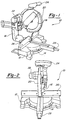
- FIG. 1 to 4 a sliding compound miter saw incorporating a table assembly in accordance with the present invention, shown merely for the purposes of illustration, and designated generally by the reference numeral 10.
- the principles of the present invention are equally applicable to sliding compound miter saws, compound miter saws, chop saws, radial arm saws, table saws or other saws of types other than that shown for purposes of illustration in the drawings.
- the principles of the table assembly according to the present invention are also applicable to other types of powered or unpowered equipment for performing an operation on a workpiece. Such equipment includes, but is not limited to, dado saws, spindle shapers or sanders, or other types of powered or unpowered devices that would benefit from the table assembly of the present invention.
- sliding compound miter saw 10 comprises a base assembly 12, a table assembly 14, a housing assembly 16, a saw blade 18, a blade guard 20, a motor 22 drivingly connected to saw blade 18, a handle 24 and a fence assembly 26.
- Table assembly 14 is secured to base assembly 12 such that it can be rotated in order to provide adjustment for miter cutting.
- the rotation of table assembly 14 changes the angle of saw blade 18 relative to fence assembly 26 but maintains the perpendicularity of saw blade 18 with table assembly 14.
- a locking mechanism 28 can be activated in order to lock table assembly 14 to base assembly 12.
- Housing assembly 16 is secured to table assembly 14 such that it can be pivoted with respect to table assembly 14 in order to provide adjustment for bevel cutting.
- the adjustments for mitering and beveling can be separate or they can be adjusted simultaneously in order to provide a compound miter and bevel cut.
- the pivoting of housing assembly 16 changes the angle of saw blade 18 relative to table assembly 14 but maintains the perpendicularity of saw blade 18 with fence assembly 26.
- a locking mechanism 30 can be activated in order to lock housing assembly 16 to table assembly 14.
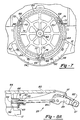
- Base assembly 12 defines a circular mounting structure 40 which includes a cylindrical cup shaped mounting boss 42 for mounting a table 44 as will be described later herein.
- Base assembly 12 also defines a plurality of threaded apertures 46 which are used to mount a detent plate 48 using a plurality of bolts 50, only one being shown in Figure 5.
- Detent plate 48 defines a plurality of slots 52 which correspond to the plurality of threaded apertures 46 in order to allow for the securing of detent plate 48 to base assembly 12 by bolts 50.
- the plurality of slots 52 permit adjustment of detent plate 48 to ensure the proper relationship of the pre-specified miter angles.
- Detent plate 48 further defines a plurality of detents 54 which are located at various popular miter angles for saw 10. Detents 54 work in conjunction with locking mechanism 28 to locate table 44 at one of the various popular miter angles as will be described later herein.
- Table assembly 14 includes table 44 and locking mechanism 28.
- Table 44 is a circular plate-like member defining a work supporting surface 56 and a mounting boss 58.
- Table 44 is rotatably mounted to base assembly 12 by inserting boss 58 of table 44 into boss 42 of base assembly 12.
- a bolt 60 is inserted through table 44 and threadably received within a threaded bore 62 ( Figure 7) in base assembly 12 to complete the assembly.
- Bolt 60 is tightened enough to secure table 44 to base assembly 12 but it is not tightened to the point of restricting rotation of table 44 with respect to base assembly 12.
- the threads on bolt 60 incorporate a patch lock to lock bolt 60 in position once it has been tightened.
- Table 44 rotates with respect to base assembly 12 in order to change the miter angle of saw 10. This rotation of table 44 changes the angular relationship of saw blade 18 with respect to fence assembly 26 but does not change the angular relationship of saw blade 18 with respect to table 44.
- Disposed between table 44 and base assembly 12 are a plurality of wear plates 64. Wear plates 64 provide a surface to support table 44 as well as reducing the friction and wear between table 44 and base assembly 12. Wear plates 64 are preferably manufactured from spring steel and protect base assembly 12 which is preferably manufactured from aluminium from excessive wear that would cause excessive play between base assembly 12 and table 44 leading to cutting inaccuracy.
- wear plates 64 are preferably manufactured from pre-hardened steel using a stamping operation. This stamping of wear plates 64 forms a burred edge on one side of wear plates 64 which needs to be positioned against the stationary base 12 such that these burred edges do not interfere with the fit or rotation of table 44.
- they are each provided with a first end 66 being cut along a radial line or perpendicular to a tangent line at that point and a second end 68 being cut at an acute angle to a radial line or an acute angle to a tangent line at that point.
- Base assembly 12 is provided with a plurality of formed shoulders 70 each of which defines a first surface 72 corresponding with first end 66 on plates 64 and a second surface 74 corresponding with second end 68 on plates 64.
- Surfaces 66, 68, 72 and 74 foolproof the assembly of plates 64 to base assembly 12 by allowing only one orientation of each wear plate 64 with respect to base assembly 12 thus ensuring that any forming burr on wear plates 64 is positioned towards base assembly 12 and not towards table 44.
- Base assembly 12 includes a circumferentially extending ring which is disposed between adjacent shoulders 70 to support and position wear plates 64.
- lock assembly 28 comprises a housing 80, a locking lever assembly 82, a threaded locking rod 84 and a locking spring 86.
- Housing 80 is a generally hollow rectangular member which is fixedly secured to table 44 such that it extends radially outward from table 44.
- Housing 80 is positioned on table 44 such that when saw blade 18 is positioned perpendicular to fence assembly 26, or a 0° miter angle, housing 80 is also generally perpendicular to fence assembly 26.
- Lever assembly 82 comprises locking lever 87 and detent trigger 89.
- Locking lever 87 and detent trigger 89 are pivotably secured to the outside end of housing 80 by a pin 81 and the threaded end of rod 84 is threadingly received.in a pin 83 which is rotatably secured to detent trigger 89 with rod 84 extending from detent trigger 89 towards table 44. A coil spring 97 biases detent trigger 89 away from locking lever 87.
- Spring 86 is fixedly secured to table 44 by a pair of bolts 88 and defines an aperture 90 which slidingly accepts the opposite end of rod 84.
- Spring 86 is a generally U-shaped component with one leg of the U defining a spring detent 92 and the opposite leg of the U defining a locking tab 94.
- spring detent 92 When spring 86 is assembled to table 44 and table 44 is assembled to base assembly 12, spring detent 92 is in biased engagement with detent plate 48 and locking tab 94 is positioned adjacent to a cylindrical surface 96 located on base assembly 12.
- a washer 91, a coil spring 93 and a retainer 95 are assembled to rod 84.
- Retainer 95 is fixedly secured to rod 84 and spring 93 reacts against washer 91 and thus spring detent 92 to increase the load with which spring detent 92 is biased into engagement with detent plate 48.
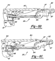
- Locking mechanism 28 can be located in any one of three positions by the movement of lever assembly 82 as illustrated in Figures 8A-8C.
- Locking mechanism 28 is shown in its locked position with locking lever 87 of lever assembly 82 being located at a position approximately 30° down from a horizontal position.
- locking lever 87 urges detent trigger 89 downward which urges locking rod 84 towards table 44 which in turn engages locking tab 94 against surface 96 of base assembly 12 locking table 44 in position relative to base assembly 12 at the specific miter angle.
- the load with which locking rod 84 engages locking tab 94 and surface 96 can be adjusted by rotating locking rod 84 within pin 83 to adjust the working length of rod 84.
- a screw driver slot 85 is provided to facilitate this adjustment and a patch lock is incorporated onto the threads of locking rod 84 to retain locking rod 84 in its desired location with respect to pin 83.
- locking mechanism 28 is shown in its engaged position with locking lever 87 of lever assembly 82 being located at a generally horizontal position. In this position, detent trigger 89 is spaced from locking lever 87 and locking rod 84 is disengaged from locking tab 94.
- Table 44 can now be rotated with respect to base assembly 12.
- Spring detent 92 is in biased engagement with detent plate 48, thus rotation of table 44 with respect to base assembly 12 will cause spring detent 92 to ratchet between the plurality of detents 54 to releasably stop at the various popular miter angles for saw 10.
- detent plate 48 is provided with slots 52 for securing plate 48 to base assembly 12 using bolts 50.
- locking mechanism 28 is shown in its released position with locking lever 87 of lever assembly 82 being located at the generally horizontal position and detent trigger 89 also being moved to a generally horizontal position.
- an annular collar 98 fixedly secured to rod 84 contacts spring detent 92 and moves it radially outward or away from detents 54.
- spring detent 92 With spring detent 92 being moved out of engagement with detents 54, the movement of table 44 with respect to base assembly 12 will occur without spring detent 92 ratcheting between detents 54.
- This position of locking mechanism 28 is especially useful when locating table 44 at a miter angle which is not pre-defined by one of detents 54 or when locating table 44 at a miter angle which is close to one of the pre-defined miter angles.
- the release of spring detent 92 eliminates the tendency of the system to jump into the adjacent detent thereby making it difficult to set a miter angle close to but not exactly equal to one of the pre-defined miter angles.
Applications Claiming Priority (4)
| Application Number | Priority Date | Filing Date | Title |
|---|---|---|---|
| US851695P | 1995-12-12 | 1995-12-12 | |
| US8516 | 1995-12-12 | ||
| US761035 | 1996-12-05 | ||
| US08/761,035 US6474206B1 (en) | 1995-12-12 | 1996-12-05 | Miter saw with wear plates and orientation system therefor |
Publications (3)
| Publication Number | Publication Date |
|---|---|
| EP0779122A2 true EP0779122A2 (de) | 1997-06-18 |
| EP0779122A3 EP0779122A3 (de) | 1997-10-01 |
| EP0779122B1 EP0779122B1 (de) | 2003-03-19 |
Family
ID=26678277
Family Applications (1)
| Application Number | Title | Priority Date | Filing Date |
|---|---|---|---|
| EP19960309075 Expired - Lifetime EP0779122B1 (de) | 1995-12-12 | 1996-12-12 | Werkstückdrehtisch |
Country Status (4)
| Country | Link |
|---|---|
| US (3) | US6474206B1 (de) |
| EP (1) | EP0779122B1 (de) |
| CN (1) | CN1066666C (de) |
| DE (1) | DE69626758T2 (de) |
Cited By (9)
| Publication number | Priority date | Publication date | Assignee | Title |
|---|---|---|---|---|
| EP1231006A2 (de) * | 2001-02-01 | 2002-08-14 | Black & Decker Inc. | Gehrungssäge |
| EP1238735A2 (de) * | 2001-01-29 | 2002-09-11 | Techtronic Industries Co., Ltd. | Ergonomischer Handgriff für eine Gehrungssäge |
| EP1410886A2 (de) * | 2002-10-16 | 2004-04-21 | Robert Bosch Tool Corporation | Gehrungswinkeleinrastsystem für eine Kapp- und Gehrungssäge |
| EP1595630A1 (de) * | 2004-05-03 | 2005-11-16 | Metabowerke GmbH | Gehrungssäge mit Winkeleinstellung |
| EP1719593A2 (de) * | 2005-05-03 | 2006-11-08 | Black & Decker, Inc. | Vorichtung zum Festklemmen des Gehrungswinkels einer Gehrungssäge |
| EP1935542A1 (de) | 2006-12-18 | 2008-06-25 | Festool GmbH | Werkzeugmaschine mit einer Rast- und Klemmeinrichtung |
| EP2754539A1 (de) * | 2012-12-07 | 2014-07-16 | D-Cut Products, INC. | Schneidewerkzeug |
| CN104070561A (zh) * | 2014-06-30 | 2014-10-01 | 江苏金飞达电动工具有限公司 | 一种斜断锯的偏转机构 |
| EP3342569A1 (de) * | 2016-12-30 | 2018-07-04 | Robert Bosch GmbH | Arretierungsmechanismus mit separat einstellbaren arretierungen |
Families Citing this family (41)
| Publication number | Priority date | Publication date | Assignee | Title |
|---|---|---|---|---|
| US6474206B1 (en) * | 1995-12-12 | 2002-11-05 | Black & Decker Inc. | Miter saw with wear plates and orientation system therefor |
| US20020100350A1 (en) * | 2001-01-16 | 2002-08-01 | Brazell Kenneth M. | Sliding fence for a compound miter saw |
| US7252027B2 (en) * | 2001-02-08 | 2007-08-07 | Black & Decker Inc. | Miter saw |
| US6810780B2 (en) * | 2001-05-10 | 2004-11-02 | Black & Decker Inc. | Miter detent override for a sliding compound miter saw |
| US6658977B2 (en) * | 2001-08-02 | 2003-12-09 | Lee-Cheng Chang | Locking mechanism for inclination adjustment of a blade of a cutting device |
| US7127977B2 (en) * | 2002-02-11 | 2006-10-31 | Porter-Cable/Delta | Remotely actuated beveling systems for a miter saw |
| TW569908U (en) * | 2002-09-26 | 2004-01-01 | P & F Brother Ind Corp | Apparatus for adjusting and aligning slant cutting angle of cutting machine |
| US20060101967A1 (en) * | 2002-11-19 | 2006-05-18 | Garcia Jaime E | Greater capacity cutting saw |
| GB2411620A (en) * | 2004-03-02 | 2005-09-07 | Black & Decker Inc | Mitre Saw |
| WO2005102626A2 (en) * | 2004-04-15 | 2005-11-03 | Milwaukee Electric Tool Corporation | Saw, such as a miter saw |
| US8061251B2 (en) * | 2004-04-15 | 2011-11-22 | Milwaukee Electric Tool Corporation | Miter adjustment assembly for a saw |
| EP1768813A2 (de) * | 2004-05-28 | 2007-04-04 | Scientific Molding Corporation Ltd. | Hand-kreissäge, insbesondere tauchsäge |
| ES2293429T3 (es) * | 2004-07-08 | 2008-03-16 | Black & Decker Inc. | Sierra de inglete con mesa giratoria. |
| AU2005202908B2 (en) * | 2004-07-13 | 2010-11-11 | Black & Decker, Inc. | Miter lock assembly for miter saws |
| CN100523073C (zh) * | 2004-07-16 | 2009-08-05 | R.T.范德比尔特公司 | 不使用金属氧化物活化剂或锌基促进剂硫化乳胶复合物 |
| CN100493831C (zh) * | 2004-08-03 | 2009-06-03 | 墩丰机械工业股份有限公司 | 切断机的任意角度定位装置 |
| US7174820B2 (en) * | 2004-10-28 | 2007-02-13 | Durq Machinery Corp. | Rip fence for cutting machine |
| JP4552873B2 (ja) * | 2006-03-08 | 2010-09-29 | 日立工機株式会社 | 卓上切断機 |
| CN201143573Y (zh) * | 2007-05-08 | 2008-11-05 | 南京德朔实业有限公司 | 斜切锯 |
| JP5103083B2 (ja) * | 2007-07-26 | 2012-12-19 | 株式会社マキタ | 卓上切断機 |
| US8695468B2 (en) | 2007-10-30 | 2014-04-15 | Robert Bosch Gmbh | Locking assembly for a power miter saw |
| TW200938352A (en) * | 2008-03-05 | 2009-09-16 | Durq Machinery Corp | Miter saw with safety positioning structure of protection cap |
| US8002253B2 (en) * | 2008-06-20 | 2011-08-23 | Robert Bosch Gmbh | Button actuated detent system |
| DE102009032844A1 (de) * | 2009-07-13 | 2011-01-20 | Maquet Gmbh & Co. Kg | Vorrichtung zur drehbaren Lagerung mindestens eines medizinischen Gerätes auf einem Boden und Verfahren zum Bremsen und/oder Feststellen einer Dreheinheit der Vorrichtung |
| TWI453080B (zh) * | 2010-03-29 | 2014-09-21 | Rexon Ind Corp Ltd | 可調整鋸切角度的鋸切機 |
| CN102756171B (zh) * | 2011-04-29 | 2015-04-22 | 苏州宝时得电动工具有限公司 | 斜断锯 |
| US9533430B1 (en) * | 2011-10-18 | 2017-01-03 | Robert M. Kalb | Portable adjustable cutting apparatus for cutting and shaping sink holes in stone countertops |
| CN102632292B (zh) * | 2012-04-09 | 2014-07-30 | 南京德朔实业有限公司 | 一种斜切锯 |
| CN103586532B (zh) * | 2013-11-08 | 2016-01-06 | 锐奇控股股份有限公司 | 斜切锯 |
| US9649776B2 (en) * | 2014-09-09 | 2017-05-16 | Michael W. Appling | Portable saw apparatus for cutting oversized substrates |
| US20160199923A1 (en) * | 2015-01-14 | 2016-07-14 | Techtronic Power Tools Technology Limited | Miter saw |
| EP3261794B1 (de) | 2015-02-25 | 2023-02-15 | Milwaukee Electric Tool Corporation | Gehrungssäge |
| US10142711B2 (en) * | 2015-04-14 | 2018-11-27 | International Business Machines Corporation | Low-crosstalk electro-optical Mach-Zehnder switch |
| US9833849B2 (en) * | 2016-01-18 | 2017-12-05 | Tti (Macao Commercial Offshore) Limited | Miter saw |
| US9849605B2 (en) * | 2016-05-28 | 2017-12-26 | Chin-Chin Chang | Power miter saw having a fence with elevated platforms |
| CN106313186A (zh) * | 2016-09-19 | 2017-01-11 | 资源县多利士木工机械有限公司 | 一种用于调节多锯片木工机锯片轴的定位装置 |
| US11020872B2 (en) * | 2017-06-13 | 2021-06-01 | Tti (Macao Commercial Offshore) Limited | Miter saw |
| WO2019108711A1 (en) * | 2017-11-28 | 2019-06-06 | Stroman, Inc. | Tray with variable positioning and support |
| JP7326062B2 (ja) | 2019-08-06 | 2023-08-15 | 株式会社マキタ | 卓上切断機 |
| US11135664B2 (en) * | 2019-08-27 | 2021-10-05 | Robert Bosch Power Tools GmbH | Table saw with a bevel pivot axis alignment arrangement |
| WO2022241399A1 (en) * | 2021-05-11 | 2022-11-17 | Black & Decker Inc. | Miter saw |
Family Cites Families (42)
| Publication number | Priority date | Publication date | Assignee | Title |
|---|---|---|---|---|
| DE130008C (de) | ||||
| US1923820A (en) | 1931-04-10 | 1933-08-22 | Gorton George | Sliding-barrel rotary-cutter-spindle cutter head |
| US2205019A (en) * | 1937-05-11 | 1940-06-18 | Millers Falls Co | Miter box |
| US2495250A (en) * | 1946-02-08 | 1950-01-24 | William O Gilly | Worktable with rotary and tilting adjustments |
| FR1011954A (fr) | 1949-05-03 | 1952-07-02 | Perfectionnement au montage des plateaux horizontaux rotatifs de machines-outils | |
| FR59618E (fr) | 1949-07-29 | 1954-06-29 | Perfectionnement au montage des plateaux horizontaux rotatifs de machines-outils | |
| GB1156468A (en) | 1967-03-09 | 1969-06-25 | Thomas Robinson & Son Ltd | Indexing of Rotary Members on Machines |
| US3498136A (en) * | 1968-03-18 | 1970-03-03 | Philip G Le May | Condiment measuring device |
| US3574315A (en) | 1968-11-04 | 1971-04-13 | B & E Products Inc | Adjustable mitre saw |
| US3611953A (en) * | 1969-05-14 | 1971-10-12 | Lorenz Schottl | Rotary table |
| US3821918A (en) | 1972-09-01 | 1974-07-02 | Rockwell International Corp | Motorized miter box |
| US3948136A (en) | 1973-12-03 | 1976-04-06 | The Stanley Works | Mitre box with improved indexing means |
| US4011782A (en) | 1975-09-25 | 1977-03-15 | The Black And Decker Manufacturing Company | Power miter saw |
| US3998121A (en) * | 1976-02-03 | 1976-12-21 | B & E Products, Inc. | Miter cutting saw |
| US4152961A (en) | 1978-01-18 | 1979-05-08 | The Singer Company | Radial saw |
| DE3120845C3 (de) | 1981-05-26 | 1994-11-17 | Peddinghaus Rolf | Metallkreissäge |
| US4452117A (en) | 1982-04-12 | 1984-06-05 | Rockwell International Corporation | Self-adjusting fence for motorized saw unit |
| US4453576A (en) * | 1982-09-24 | 1984-06-12 | Burns W Mike | Apparatus for filling containers such as communion cups |
| AT384386B (de) * | 1983-06-28 | 1987-11-10 | Walter Sticht | Einrichtung zur handhabung bzw. positionierung von bauteilen |
| DE3329496C2 (de) * | 1983-08-16 | 1986-02-06 | Eugen Lutz GmbH u. Co Maschinenfabrik, 7130 Mühlacker | Sägeeinrichtung |
| DE8327663U1 (de) | 1983-09-27 | 1984-03-08 | Black & Decker Inc., 19711 Newark, Del. | Kappsaege |
| US4665782A (en) | 1986-01-08 | 1987-05-19 | Tri Tool Inc. | Bearing arrangement for portable lathe |
| US4934233B1 (en) | 1988-06-29 | 1994-08-23 | Emerson Electric Co | Compound miter saw |
| JP2573057B2 (ja) | 1989-07-07 | 1997-01-16 | 株式会社マキタ | 卓上丸鋸盤 |
| DE4033037A1 (de) | 1990-10-18 | 1992-04-23 | Lutz Eugen Masch | Gehrungskappsaege |
| JPH074097Y2 (ja) * | 1991-02-05 | 1995-02-01 | リョービ株式会社 | テーブル付き丸鋸における角度調整装置 |
| US5235889A (en) | 1992-03-25 | 1993-08-17 | Delta International Machinery Corp. | Compound miter saw |
| CA2064619C (en) | 1992-03-25 | 2000-10-17 | Louis C. Brickner | Motorized miter box |
| US5249496A (en) | 1992-08-13 | 1993-10-05 | Milwaukee Electric Tool Corporation | Indexing detent override mechanism |
| US5791224A (en) * | 1994-03-24 | 1998-08-11 | Ryobi Limited | Circular sawing machine |
| CN2224054Y (zh) * | 1994-04-29 | 1996-04-10 | 张家港和丰机械制造有限公司 | 金属圆锯机 |
| CN2209567Y (zh) * | 1994-05-09 | 1995-10-11 | 刘振国 | 多功能切割锯 |
| US5595124A (en) * | 1994-06-08 | 1997-01-21 | Delta International Machinery Corp. | Restraining mechanism |
| TW275049B (de) * | 1994-06-08 | 1996-05-01 | Delta Int Machinery Corp | |
| US5560273A (en) * | 1994-06-09 | 1996-10-01 | Hempe Manufacturing Co., Inc. | Miter box with vertical and horizontal angular positioning devices |
| US5819624A (en) * | 1996-07-30 | 1998-10-13 | Milwaukee Electric Tool Corporation | Indexing override mechanism for a slide compound miter saw |
| US5862732A (en) * | 1996-07-30 | 1999-01-26 | Milwaukee Electric Tool Corporation | Support assembly for a slide compound miter saw |
| GB2304075B (en) * | 1995-08-10 | 1999-10-20 | Milwaukee Electric Tool Corp | Indexing override mechanism for a slide compound miter saw |
| US5937720A (en) * | 1995-08-10 | 1999-08-17 | Milwaukee Electric Tool Corporation | Lower blade guard actuating mechanism for a slide compound miter saw |
| JP3331105B2 (ja) * | 1995-10-05 | 2002-10-07 | 株式会社マキタ | マルノコの傾斜ストッパ装置 |
| US6474206B1 (en) * | 1995-12-12 | 2002-11-05 | Black & Decker Inc. | Miter saw with wear plates and orientation system therefor |
| JP3283745B2 (ja) * | 1996-02-05 | 2002-05-20 | 株式会社マキタ | 電動工具の操作レバー |
-
1996
- 1996-12-05 US US08/761,035 patent/US6474206B1/en not_active Expired - Fee Related
- 1996-12-12 CN CN96121357A patent/CN1066666C/zh not_active Expired - Fee Related
- 1996-12-12 EP EP19960309075 patent/EP0779122B1/de not_active Expired - Lifetime
- 1996-12-12 DE DE1996626758 patent/DE69626758T2/de not_active Expired - Lifetime
-
2002
- 2002-10-18 US US10/273,724 patent/US7013780B2/en not_active Expired - Fee Related
-
2005
- 2005-11-29 US US11/288,457 patent/US7210415B2/en not_active Expired - Fee Related
Non-Patent Citations (1)
| Title |
|---|
| None |
Cited By (17)
| Publication number | Priority date | Publication date | Assignee | Title |
|---|---|---|---|---|
| AU785237B2 (en) * | 2001-01-29 | 2006-11-23 | Techtronic Industries Co., Ltd. | Ergonomic miter saw handle |
| EP1238735A2 (de) * | 2001-01-29 | 2002-09-11 | Techtronic Industries Co., Ltd. | Ergonomischer Handgriff für eine Gehrungssäge |
| EP1238735A3 (de) * | 2001-01-29 | 2003-10-15 | Techtronic Industries Co., Ltd. | Ergonomischer Handgriff für eine Gehrungssäge |
| EP1231006A3 (de) * | 2001-02-01 | 2003-11-19 | Black & Decker Inc. | Gehrungssäge |
| EP1231006A2 (de) * | 2001-02-01 | 2002-08-14 | Black & Decker Inc. | Gehrungssäge |
| US7617755B2 (en) | 2001-02-01 | 2009-11-17 | Black & Decker Inc. | Miter saw |
| EP1410886A2 (de) * | 2002-10-16 | 2004-04-21 | Robert Bosch Tool Corporation | Gehrungswinkeleinrastsystem für eine Kapp- und Gehrungssäge |
| EP1410886A3 (de) * | 2002-10-16 | 2004-08-18 | Robert Bosch Tool Corporation | Gehrungswinkeleinrastsystem für eine Kapp- und Gehrungssäge |
| EP1595630A1 (de) * | 2004-05-03 | 2005-11-16 | Metabowerke GmbH | Gehrungssäge mit Winkeleinstellung |
| US7302879B2 (en) | 2004-05-03 | 2007-12-04 | Metabowerke Gmbh | Miter saw with angle adjustment |
| EP1719593A2 (de) * | 2005-05-03 | 2006-11-08 | Black & Decker, Inc. | Vorichtung zum Festklemmen des Gehrungswinkels einer Gehrungssäge |
| EP1719593A3 (de) * | 2005-05-03 | 2007-01-17 | Black & Decker, Inc. | Vorichtung zum Festklemmen des Gehrungswinkels einer Gehrungssäge |
| EP1857208A1 (de) | 2005-05-03 | 2007-11-21 | Black & Decker, Inc. | Gehrungssäge |
| EP1935542A1 (de) | 2006-12-18 | 2008-06-25 | Festool GmbH | Werkzeugmaschine mit einer Rast- und Klemmeinrichtung |
| EP2754539A1 (de) * | 2012-12-07 | 2014-07-16 | D-Cut Products, INC. | Schneidewerkzeug |
| CN104070561A (zh) * | 2014-06-30 | 2014-10-01 | 江苏金飞达电动工具有限公司 | 一种斜断锯的偏转机构 |
| EP3342569A1 (de) * | 2016-12-30 | 2018-07-04 | Robert Bosch GmbH | Arretierungsmechanismus mit separat einstellbaren arretierungen |
Also Published As
| Publication number | Publication date |
|---|---|
| US20060075866A1 (en) | 2006-04-13 |
| DE69626758D1 (de) | 2003-04-24 |
| CN1165064A (zh) | 1997-11-19 |
| CN1066666C (zh) | 2001-06-06 |
| EP0779122B1 (de) | 2003-03-19 |
| US7013780B2 (en) | 2006-03-21 |
| US6474206B1 (en) | 2002-11-05 |
| DE69626758T2 (de) | 2003-07-17 |
| EP0779122A3 (de) | 1997-10-01 |
| US20030037656A1 (en) | 2003-02-27 |
| US7210415B2 (en) | 2007-05-01 |
Similar Documents
| Publication | Publication Date | Title |
|---|---|---|
| US6474206B1 (en) | Miter saw with wear plates and orientation system therefor | |
| US6810780B2 (en) | Miter detent override for a sliding compound miter saw | |
| US5755148A (en) | Adjustable fence for a compound miter saw | |
| EP0779121B1 (de) | Blockiersystem | |
| EP0860250B1 (de) | Gehrungssägeschwenklagerfestspannvorrichtung | |
| US5865079A (en) | Adjustable workpiece support apparatus for a compound miter saw | |
| EP1644166B1 (de) | Kreissäge mit gehrungswinkel- und schnittiefeneinrastsystem | |
| EP1577065B1 (de) | Schneidblatt- und Motorträger mit Höhe/Winkel-Einstellvorrichtung | |
| EP1944140A2 (de) | Schrägsperrsystem für eine zusammengesetzte Gleittischkreissäge | |
| US20040074363A1 (en) | Bevel angle detent system for a compound miter saw | |
| US6631661B2 (en) | Bevel locking system for a sliding compound miter saw | |
| EP1568432B1 (de) | Gehrungssäge | |
| US6032562A (en) | Bevel locking system for a sliding compound miter saw |
Legal Events
| Date | Code | Title | Description |
|---|---|---|---|
| PUAI | Public reference made under article 153(3) epc to a published international application that has entered the european phase |
Free format text: ORIGINAL CODE: 0009012 |
|
| AK | Designated contracting states |
Kind code of ref document: A2 Designated state(s): DE FR GB IT |
|
| PUAL | Search report despatched |
Free format text: ORIGINAL CODE: 0009013 |
|
| AK | Designated contracting states |
Kind code of ref document: A3 Designated state(s): DE FR GB IT |
|
| 17P | Request for examination filed |
Effective date: 19980319 |
|
| 17Q | First examination report despatched |
Effective date: 19991103 |
|
| GRAG | Despatch of communication of intention to grant |
Free format text: ORIGINAL CODE: EPIDOS AGRA |
|
| GRAG | Despatch of communication of intention to grant |
Free format text: ORIGINAL CODE: EPIDOS AGRA |
|
| GRAH | Despatch of communication of intention to grant a patent |
Free format text: ORIGINAL CODE: EPIDOS IGRA |
|
| GRAH | Despatch of communication of intention to grant a patent |
Free format text: ORIGINAL CODE: EPIDOS IGRA |
|
| GRAA | (expected) grant |
Free format text: ORIGINAL CODE: 0009210 |
|
| AK | Designated contracting states |
Designated state(s): DE FR GB IT |
|
| REG | Reference to a national code |
Ref country code: GB Ref legal event code: FG4D |
|
| REF | Corresponds to: |
Ref document number: 69626758 Country of ref document: DE Date of ref document: 20030424 Kind code of ref document: P |
|
| ET | Fr: translation filed | ||
| PLBE | No opposition filed within time limit |
Free format text: ORIGINAL CODE: 0009261 |
|
| STAA | Information on the status of an ep patent application or granted ep patent |
Free format text: STATUS: NO OPPOSITION FILED WITHIN TIME LIMIT |
|
| 26N | No opposition filed |
Effective date: 20031222 |
|
| PGFP | Annual fee paid to national office [announced via postgrant information from national office to epo] |
Ref country code: FR Payment date: 20071217 Year of fee payment: 12 |
|
| REG | Reference to a national code |
Ref country code: FR Ref legal event code: ST Effective date: 20090831 |
|
| PG25 | Lapsed in a contracting state [announced via postgrant information from national office to epo] |
Ref country code: FR Free format text: LAPSE BECAUSE OF NON-PAYMENT OF DUE FEES Effective date: 20081231 |
|
| PGFP | Annual fee paid to national office [announced via postgrant information from national office to epo] |
Ref country code: GB Payment date: 20101229 Year of fee payment: 15 Ref country code: IT Payment date: 20101228 Year of fee payment: 15 |
|
| PGFP | Annual fee paid to national office [announced via postgrant information from national office to epo] |
Ref country code: DE Payment date: 20111229 Year of fee payment: 16 |
|
| GBPC | Gb: european patent ceased through non-payment of renewal fee |
Effective date: 20121212 |
|
| REG | Reference to a national code |
Ref country code: DE Ref legal event code: R119 Ref document number: 69626758 Country of ref document: DE Effective date: 20130702 |
|
| PG25 | Lapsed in a contracting state [announced via postgrant information from national office to epo] |
Ref country code: DE Free format text: LAPSE BECAUSE OF NON-PAYMENT OF DUE FEES Effective date: 20130702 |
|
| PG25 | Lapsed in a contracting state [announced via postgrant information from national office to epo] |
Ref country code: GB Free format text: LAPSE BECAUSE OF NON-PAYMENT OF DUE FEES Effective date: 20121212 |
|
| PG25 | Lapsed in a contracting state [announced via postgrant information from national office to epo] |
Ref country code: IT Free format text: LAPSE BECAUSE OF NON-PAYMENT OF DUE FEES Effective date: 20121212 |