EP0778370B1 - Verfahren zur Zugabe von reduzierendem Bleichmittel zu einem hochkonsistenten Papierfaserstoff - Google Patents
Verfahren zur Zugabe von reduzierendem Bleichmittel zu einem hochkonsistenten Papierfaserstoff Download PDFInfo
- Publication number
- EP0778370B1 EP0778370B1 EP96116115A EP96116115A EP0778370B1 EP 0778370 B1 EP0778370 B1 EP 0778370B1 EP 96116115 A EP96116115 A EP 96116115A EP 96116115 A EP96116115 A EP 96116115A EP 0778370 B1 EP0778370 B1 EP 0778370B1
- Authority
- EP
- European Patent Office
- Prior art keywords
- pulp
- compression
- zone
- paper pulp
- bleach
- Prior art date
- Legal status (The legal status is an assumption and is not a legal conclusion. Google has not performed a legal analysis and makes no representation as to the accuracy of the status listed.)
- Expired - Lifetime
Links
- 239000007844 bleaching agent Substances 0.000 title claims abstract description 39
- 238000000034 method Methods 0.000 title claims abstract description 36
- 239000002657 fibrous material Substances 0.000 title description 8
- 238000009895 reductive bleaching Methods 0.000 title description 3
- 238000007906 compression Methods 0.000 claims abstract description 30
- 229920001131 Pulp (paper) Polymers 0.000 claims abstract description 26
- 230000006835 compression Effects 0.000 claims abstract description 25
- 239000000126 substance Substances 0.000 abstract description 20
- 238000004061 bleaching Methods 0.000 abstract description 15
- 239000000463 material Substances 0.000 abstract description 4
- 239000006185 dispersion Substances 0.000 abstract description 3
- 239000000835 fiber Substances 0.000 description 8
- 238000007792 addition Methods 0.000 description 6
- 230000000694 effects Effects 0.000 description 4
- 238000006243 chemical reaction Methods 0.000 description 3
- 238000004898 kneading Methods 0.000 description 3
- 239000004744 fabric Substances 0.000 description 2
- 230000002349 favourable effect Effects 0.000 description 2
- 238000003754 machining Methods 0.000 description 2
- 239000010893 paper waste Substances 0.000 description 2
- 239000007787 solid Substances 0.000 description 2
- 238000011144 upstream manufacturing Methods 0.000 description 2
- 241000237858 Gastropoda Species 0.000 description 1
- QVGXLLKOCUKJST-UHFFFAOYSA-N atomic oxygen Chemical compound [O] QVGXLLKOCUKJST-UHFFFAOYSA-N 0.000 description 1
- 230000003749 cleanliness Effects 0.000 description 1
- 239000000356 contaminant Substances 0.000 description 1
- GRWZHXKQBITJKP-UHFFFAOYSA-L dithionite(2-) Chemical compound [O-]S(=O)S([O-])=O GRWZHXKQBITJKP-UHFFFAOYSA-L 0.000 description 1
- 229940082150 encore Drugs 0.000 description 1
- 230000003993 interaction Effects 0.000 description 1
- 239000007800 oxidant agent Substances 0.000 description 1
- 229910052760 oxygen Inorganic materials 0.000 description 1
- 239000001301 oxygen Substances 0.000 description 1
- 150000002978 peroxides Chemical class 0.000 description 1
- 239000002994 raw material Substances 0.000 description 1
- XLYOFNOQVPJJNP-UHFFFAOYSA-N water Substances O XLYOFNOQVPJJNP-UHFFFAOYSA-N 0.000 description 1
Images


Classifications
-
- B—PERFORMING OPERATIONS; TRANSPORTING
- B01—PHYSICAL OR CHEMICAL PROCESSES OR APPARATUS IN GENERAL
- B01F—MIXING, e.g. DISSOLVING, EMULSIFYING OR DISPERSING
- B01F35/00—Accessories for mixers; Auxiliary operations or auxiliary devices; Parts or details of general application
- B01F35/71—Feed mechanisms
- B01F35/717—Feed mechanisms characterised by the means for feeding the components to the mixer
- B01F35/71775—Feed mechanisms characterised by the means for feeding the components to the mixer using helical screws
-
- D—TEXTILES; PAPER
- D21—PAPER-MAKING; PRODUCTION OF CELLULOSE
- D21C—PRODUCTION OF CELLULOSE BY REMOVING NON-CELLULOSE SUBSTANCES FROM CELLULOSE-CONTAINING MATERIALS; REGENERATION OF PULPING LIQUORS; APPARATUS THEREFOR
- D21C9/00—After-treatment of cellulose pulp, e.g. of wood pulp, or cotton linters ; Treatment of dilute or dewatered pulp or process improvement taking place after obtaining the raw cellulosic material and not provided for elsewhere
- D21C9/10—Bleaching ; Apparatus therefor
-
- B—PERFORMING OPERATIONS; TRANSPORTING
- B01—PHYSICAL OR CHEMICAL PROCESSES OR APPARATUS IN GENERAL
- B01F—MIXING, e.g. DISSOLVING, EMULSIFYING OR DISPERSING
- B01F23/00—Mixing according to the phases to be mixed, e.g. dispersing or emulsifying
- B01F23/50—Mixing liquids with solids
- B01F23/56—Mixing liquids with solids by introducing solids in liquids, e.g. dispersing or dissolving
-
- B—PERFORMING OPERATIONS; TRANSPORTING
- B01—PHYSICAL OR CHEMICAL PROCESSES OR APPARATUS IN GENERAL
- B01F—MIXING, e.g. DISSOLVING, EMULSIFYING OR DISPERSING
- B01F27/00—Mixers with rotary stirring devices in fixed receptacles; Kneaders
- B01F27/27—Mixers with stator-rotor systems, e.g. with intermeshing teeth or cylinders or having orifices
- B01F27/271—Mixers with stator-rotor systems, e.g. with intermeshing teeth or cylinders or having orifices with means for moving the materials to be mixed radially between the surfaces of the rotor and the stator
-
- B—PERFORMING OPERATIONS; TRANSPORTING
- B01—PHYSICAL OR CHEMICAL PROCESSES OR APPARATUS IN GENERAL
- B01F—MIXING, e.g. DISSOLVING, EMULSIFYING OR DISPERSING
- B01F27/00—Mixers with rotary stirring devices in fixed receptacles; Kneaders
- B01F27/60—Mixers with rotary stirring devices in fixed receptacles; Kneaders with stirrers rotating about a horizontal or inclined axis
- B01F27/62—Mixers with rotary stirring devices in fixed receptacles; Kneaders with stirrers rotating about a horizontal or inclined axis comprising liquid feeding, e.g. spraying means
-
- B—PERFORMING OPERATIONS; TRANSPORTING
- B01—PHYSICAL OR CHEMICAL PROCESSES OR APPARATUS IN GENERAL
- B01F—MIXING, e.g. DISSOLVING, EMULSIFYING OR DISPERSING
- B01F35/00—Accessories for mixers; Auxiliary operations or auxiliary devices; Parts or details of general application
- B01F35/71—Feed mechanisms
- B01F35/717—Feed mechanisms characterised by the means for feeding the components to the mixer
- B01F35/71805—Feed mechanisms characterised by the means for feeding the components to the mixer using valves, gates, orifices or openings
-
- D—TEXTILES; PAPER
- D21—PAPER-MAKING; PRODUCTION OF CELLULOSE
- D21C—PRODUCTION OF CELLULOSE BY REMOVING NON-CELLULOSE SUBSTANCES FROM CELLULOSE-CONTAINING MATERIALS; REGENERATION OF PULPING LIQUORS; APPARATUS THEREFOR
- D21C9/00—After-treatment of cellulose pulp, e.g. of wood pulp, or cotton linters ; Treatment of dilute or dewatered pulp or process improvement taking place after obtaining the raw cellulosic material and not provided for elsewhere
- D21C9/10—Bleaching ; Apparatus therefor
- D21C9/1084—Bleaching ; Apparatus therefor with reducing compounds
-
- B—PERFORMING OPERATIONS; TRANSPORTING
- B01—PHYSICAL OR CHEMICAL PROCESSES OR APPARATUS IN GENERAL
- B01F—MIXING, e.g. DISSOLVING, EMULSIFYING OR DISPERSING
- B01F25/00—Flow mixers; Mixers for falling materials, e.g. solid particles
- B01F2025/91—Direction of flow or arrangement of feed and discharge openings
- B01F2025/912—Radial flow
- B01F2025/9121—Radial flow from the center to the circumference, i.e. centrifugal flow
-
- B—PERFORMING OPERATIONS; TRANSPORTING
- B01—PHYSICAL OR CHEMICAL PROCESSES OR APPARATUS IN GENERAL
- B01F—MIXING, e.g. DISSOLVING, EMULSIFYING OR DISPERSING
- B01F23/00—Mixing according to the phases to be mixed, e.g. dispersing or emulsifying
- B01F23/50—Mixing liquids with solids
- B01F23/57—Mixing high-viscosity liquids with solids
-
- B—PERFORMING OPERATIONS; TRANSPORTING
- B01—PHYSICAL OR CHEMICAL PROCESSES OR APPARATUS IN GENERAL
- B01F—MIXING, e.g. DISSOLVING, EMULSIFYING OR DISPERSING
- B01F27/00—Mixers with rotary stirring devices in fixed receptacles; Kneaders
- B01F27/27—Mixers with stator-rotor systems, e.g. with intermeshing teeth or cylinders or having orifices
- B01F27/271—Mixers with stator-rotor systems, e.g. with intermeshing teeth or cylinders or having orifices with means for moving the materials to be mixed radially between the surfaces of the rotor and the stator
- B01F27/2711—Mixers with stator-rotor systems, e.g. with intermeshing teeth or cylinders or having orifices with means for moving the materials to be mixed radially between the surfaces of the rotor and the stator provided with intermeshing elements
-
- B—PERFORMING OPERATIONS; TRANSPORTING
- B01—PHYSICAL OR CHEMICAL PROCESSES OR APPARATUS IN GENERAL
- B01F—MIXING, e.g. DISSOLVING, EMULSIFYING OR DISPERSING
- B01F27/00—Mixers with rotary stirring devices in fixed receptacles; Kneaders
- B01F27/60—Mixers with rotary stirring devices in fixed receptacles; Kneaders with stirrers rotating about a horizontal or inclined axis
-
- B—PERFORMING OPERATIONS; TRANSPORTING
- B01—PHYSICAL OR CHEMICAL PROCESSES OR APPARATUS IN GENERAL
- B01F—MIXING, e.g. DISSOLVING, EMULSIFYING OR DISPERSING
- B01F35/00—Accessories for mixers; Auxiliary operations or auxiliary devices; Parts or details of general application
- B01F35/71—Feed mechanisms
Definitions
- the invention relates to a method for adding reducing bleach a high-consistency paper pulp according to the preamble of claim 1.
- WO-A-87/05346 a method in which a disperger as Bleach mixer is used.
- a disperger as Bleach mixer
- Dithionite as a reducing bleach metered into the chute, through which the highly consistent fiber material of the Feed screw of the disperser is fed.
- WO-A-94/27713 also discloses the Bleaching chemicals in front of the dispersing machine, in one there feed upstream so-called forced conveyors. This has a snail with an axial hollow shaft through which the bleaching chemicals are conveyed can. Only then does the highly consistent fibrous material enter the space between the Disperger sets.
- the invention has for its object the reducing bleaching agents used use even more effectively and as completely as possible to bleach the paper pulp to be able to improve the bleaching process.
- the bleaching chemicals are namely on one fed to such a place where the material is already compressed, possibly is also a little more open-minded, but on the other hand still with the other Sufficient processing within the dispersing machine with the bleach be mixed.
- the chemical bleaching then runs optimally.
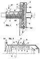
- Fig. 1 shows the method according to the invention schematically, being an example of the Dispersing machine 3 a toothed disk disperger is indicated, with a rotor 5 and a stator 6.
- the paper pulp S1 has already been dewatered and pre-shredded and Besides the paper fibers and water, it can also contain other accompanying substances, possibly also Contain contaminants. In this highly consistent form (approx. 15-25% dry matter) it is often referred to as crumbly. It enters the through a chute Feeder 1 with a transport and stuffing screw 2. He can Have a temperature above 80 ° C. In the interior of this feed device incident paper pulp already pre-compressed, which is shown schematically by a Dot area is indicated.
- the paper pulp S2 pre-compressed in this way then enters the processing area 3 of the dispersing machine, in which it is further compressed to the paper pulp S3, indicated by a darker dot area.
- the compression can have an open air content of less than 1% of the pulp (Wet weight).
- a bleaching agent B is added to it by a bleaching agent addition device 4, 4 '.
- the specific work transferred is at least 30 kWh / t.
- the bleach (B) can be added where at least the Half of the total specific dispersion work was done.
- the bleaching agent (B) can preferably be added at the point a specific dispersion work on the paper pulp of at least 20 kWh / t.
- the Highly compressed paper pulp S3 is therefore processed mechanically intensively as well as mixed with the bleach.
- the method according to the invention can also be carried out axially from the fiber material perform kneading machine with flow, as shown for example in FIG. 2.
- a machine known per se can be used to disperse pulp be, the kneading by machining pin 7, which on a shaft 9th are attached, in cooperation with other pins 8, which are on the inside of the Housing 10 are attached.
- the pins and possibly other parts of the Machine shaped so that the fabric is increasingly narrow or less numerous Cross sections is compressed.
- the paper pulp S1 becomes like with arrows indicated, fed on the left with the help of a screw, passes the processing area 3 'and leaves the dispersing machine on the right (S4). Because even within one The inventive kneading machine compresses the fibrous material applied by e.g. through the wall of the housing 10 to the bleach the places where the substance is already sufficiently compressed, i.e. contains as little free air as possible.
- Fig. 3 shows the structure of a somewhat more detailed, but still schematic Toothed-disk dispergers at the point at which the bleach addition device 4, 4 ' is mounted.
- the housing of the dispersing machine is not shown. you recognizes the stator 6 and the rotor 7, which are provided with teeth 11 and 12, respectively are. In operation, radially adjacent teeth move relative to one another, e.g. With a relative speed of over 10 m / s up to at least 30 m / s. Hold on a distance that is usually only a few millimeters. In that way forming columns, the fibrous material is worked intensively with shear forces and compressed.
- a bore 13 is expediently made on the stator side, via a connection 14 the supply of the bleaching chemicals into the fabric area the dispersing machine allowed. Since it is not always certain from the outset From a radial point of view, it makes sense to add such chemicals be favorable to provide several such additions radially with the holes 13, 13 'in order to be able to optimize the process. Number and location of such Bleach addition devices depend on the respective requirements. at A machine of the type shown here is distributed over the circumference Facilities that make sense, for example, belong to the stator, because there the Connections for the bleach are easy to attach. But also radially successive bleach addition devices are conceivable, which either used alternatively or together. The offer would also be very targeted different chemicals in the direction of flow of the substance very easily possible.
- Fig. 4 essentially shows the device shown in Fig. 3 in another View so that the annular arrangement of the teeth 11 and 12 is visible.
- the cut is made so that the teeth of both parts of the machine, i.e. the stator and the Rotors to be cut. It can also be seen in the supervision that the bores 13, 13 'for the bleaching agent each end in the tooth base of a stator ring.
- the Compression of the pulp takes place discontinuously, i.e. it will be one first High compression zone 17 is formed, which then adjoins a zone downstream the compression is initially lower and into which the bleaching agent B is added.
- the clothing has a back-barrage, which as Lock for the entrained air is used.
- a very good equipment option for this is the attachment of a toothed ring 15 rotatable in the circumferential direction, which in Interaction with the fitting part immediately upstream in front of it, which is also a toothed ring with teeth 12, a reinforced one Throttling effect developed.
- the throttling effect can be achieved by turning the Toothed ring 15 are easily adjusted in the circumferential direction, since the overlap of the Can change teeth.
- the schematically shown adjustment device is used for this purpose 16th
- discontinuity of the compression is here based on a special one in the circumferential direction rotatable toothed ring has been explained, but there are also toothless, axial Slidable rings or other adjustable throttle elements are conceivable. Also in Intermittent compression is easily feasible if the described teaching is transferred accordingly.
- the high compression zone 17 as the initial processing zone of the Machining area selected which is usually the best solution, can originally contained air, possibly also the steam, backwards to Transport screw 2 escape, i.e. against the direction of transport of the highly consistent Fiber S2.
- bleach B is advantageously added. In many cases, the pulp can already sufficiently dispersed when passing through the high compression zone 17. By doing subsequent part of the processing zone 3 then outweighs the mixing effect.
Landscapes
- Chemical & Material Sciences (AREA)
- Chemical Kinetics & Catalysis (AREA)
- Life Sciences & Earth Sciences (AREA)
- Engineering & Computer Science (AREA)
- Wood Science & Technology (AREA)
- Dispersion Chemistry (AREA)
- Paper (AREA)
- Detergent Compositions (AREA)
Description
- Fig. 1
- die verfahrensmäßigen Abläufe am Beispiel eines Dispergers;
- Fig. 2
- eine Vorrichtung zur Durchführung des Verfahrens;
- Fig. 3
- Teil einer weiteren Vorrichtung zur Durchführung des Verfahrens;
- Fig. 4
- eine andere Ansicht der in Fig. 3 gezeigten Vorrichtung;
- Fig. 5
- Teil einer weiteren Vorrichtung zur Durchführung des Verfahrens;
- Fig. 6
- Teil einer Vorrichtung zur unstetigen Kompression.
Claims (15)
- Verfahren zur Zugabe von reduzierendem Bleichmittel (B) zu einem hochkonsistenten Papierfaserstoff (S1, S2, S3) unter Verwendung einer Dispergiermaschine mit einem Bearbeitungsbereich (3,3'), in dem sowohl eine Kompression des Papierfaserstoffs als auch eine Vermischung des Bleichmittels (B) mit dem Papierfaserstoff erfolgen,
dadurch gekennzeichnet, dass die Zugabe des Bleichmittels (B) an mehreren Stellen innerhalb des Bearbeitungsbereiches (3,3') der Dispergiermaschine erfolgt. - Verfahren nach Anspruch 1,
dadurch gekennzeichnet, dass der hochkonsistente Papierfaserstoff (S1, S2, S3) im Bearbeitungsbereich (3, 3') der Dispergiermaschine eine Temperatur von über 80° Celsius hat. - Verfahren nach Anspruch 1 oder 2,
dadurch gekennzeichnet, dass die in der Dispergiermaschine auf den Papierfaserstoff (S1, S2, S3) übertragene spezifische Arbeit mindestens 30 kWh/t beträgt. - Verfahren nach Anspruch 1, 2 oder 3,
dadurch gekennzeichnet, dass die Kompression des Papierfaserstoffs (S1, S2, S3) innerhalb des Bearbeitungsbereiches (3, 3') einen solchen Grad erreicht, dass der Gehalt an freier Luft weniger als 1 % des Faserstoffs (Feuchtmasse) beträgt. - Verfahren nach einem der Ansprüche 1 bis 4,
dadurch gekennzeichnet, dass die Kompression des Papierfaserstoffes (S1, S2, S3) innerhalb des Bearbeitungsbereiches (3, 3') unstetig erfolgt, indem mindestens eine Hochkompressionszone (17) gebildet wird, der eine Zone von geringerer oder keiner Kompression folgt, in die das reduzierende Bleichmittel (B) eingegeben wird. - Verfahren nach Anspruch 5,
dadurch gekennzeichnet, dass die Hochkompressionszone (17) im initialen Teil des Bearbeitungsbereiches (3, 3') liegt. - Verfahren nach Anspruch 5 oder 6,
dadurch gekennzeichnet, dass der Grad der Kompression in der Hochkompressionszone (17) während des Betriebes verstellbar ist - Verfahren nach Anspruch 7,
dadurch gekennzeichnet, dass sich am Ende der Hochkompressionszone (17) veränderbare offene Querschnitte befinden, durch die der hochkonsistente Faserstoff hindurchtritt. - Verfahren nach Anspruch 5, 6, 7 oder 8,
dadurch gekennzeichnet, dass in der sich der Hochkompressionszone (17) anschließenden Zone eine Temperatur von über 100° C und ein Druck von über 1 bar herrschen. - Verfahren nach einem der voranstehenden Ansprüche,
dadurch gekennzeichnet, dass am stromabwärtigen Ende des Bearbeitungsbereiches (3,3') eine einstellbare Drosselung des Durchflusses erfolgt. - Verfahren nach einem der Ansprüche 1 bis 10,
dadurch gekennzeichnet, dass die Dispergiermaschine mit ringförmigen Zahngarnituren versehen ist, wobei der Papierfaserstoff radial zwischen diesen Zähnen (11, 12) hindurchgeführt wird und die Zähne in geringem Abstand voneinander mit einer Relativgeschwindigkeit von über 10 m/s bewegt werden und dass die Zugabe des Bleichmittels (B) in Zwischenräumen zwischen den Zähnen (11, 12) mindestens einer dieser Zahngarnituren erfolgt. - Verfahren nach Anspruch 11,
dadurch gekennzeichnet, dass die Relativgeschwindigkeit mindestens 30 m/s beträgt. - Verfahren nach einem der voranstehenden Ansprüche,
dadurch gekennzeichnet, dass die Dispergiermaschine (3') mit einem Gehäuse (10) und mindestens einer Kneterwelle (9) versehen ist, die an ihrem Außendurchmesser Bearbeitungszapfen (7) aufweist, die relativ zu weiteren im Gehäuseinnenraum angebrachten, feststehenden Zapfen (8) bewegt werden, wobei der Papierfaserstoff (S1, S2, S3) im wesentlichen axial in dem Raum zwischen Kneterwelle (9) und Gehäusewand geführt wird und dass die Zugabe des Bleichmittels (B) in Zwischenräumen zwischen den feststehenden Zapfen (8) erfolgt. - Verfahren nach einem der voranstehenden Ansprüche,
dadurch gekennzeichnet, dass die Zugabe des Bleichmittels (B) an der Stelle erfolgt, an der am Papierfaserstoff bereits mindestens die Hälfte der gesamten spezifischen Dispergierarbeit verrichtet wurde. - Verfahren nach einem der voranstehenden Ansprüche,
dadurch gekennzeichnet, dass die Zugabe des Bleichmittels (B) an der Stelle erfolgt, an der am Papierfaserstoff bereits eine spezifische Dispergierarbeit von mindestens 20 kWh/t verrichtet wurde.
Applications Claiming Priority (2)
| Application Number | Priority Date | Filing Date | Title |
|---|---|---|---|
| DE19545852A DE19545852A1 (de) | 1995-12-08 | 1995-12-08 | Verfahren zur Zugabe von reduzierendem Bleichmittel zu einem hochkonsistenten Papierfaserstoff |
| DE19545852 | 1995-12-08 |
Publications (2)
| Publication Number | Publication Date |
|---|---|
| EP0778370A1 EP0778370A1 (de) | 1997-06-11 |
| EP0778370B1 true EP0778370B1 (de) | 2002-04-17 |
Family
ID=7779570
Family Applications (1)
| Application Number | Title | Priority Date | Filing Date |
|---|---|---|---|
| EP96116115A Expired - Lifetime EP0778370B1 (de) | 1995-12-08 | 1996-10-09 | Verfahren zur Zugabe von reduzierendem Bleichmittel zu einem hochkonsistenten Papierfaserstoff |
Country Status (4)
| Country | Link |
|---|---|
| EP (1) | EP0778370B1 (de) |
| AT (1) | ATE216443T1 (de) |
| DE (2) | DE19545852A1 (de) |
| NO (1) | NO965179L (de) |
Families Citing this family (2)
| Publication number | Priority date | Publication date | Assignee | Title |
|---|---|---|---|---|
| DE102008022355A1 (de) | 2008-05-06 | 2009-11-19 | Axel Wittek | Rotor-Stator-System zum Herstellen von Dispersionen |
| US12521726B2 (en) * | 2021-06-18 | 2026-01-13 | Lg Chem, Ltd. | Micronizing apparatus for hydrogel of super absorbent polymer |
Family Cites Families (3)
| Publication number | Priority date | Publication date | Assignee | Title |
|---|---|---|---|---|
| US2716926A (en) * | 1951-01-02 | 1955-09-06 | Jackson And Church Company | Apparatus for treating wood pulp |
| DE3610940A1 (de) * | 1986-03-04 | 1987-09-10 | Escher Wyss Gmbh | Hochtemperatur-hochkonsistenz-schnellbleiche |
| AT398991B (de) * | 1993-05-24 | 1995-02-27 | Andritz Patentverwaltung | Mischer, insbesondere hochleistungsmischer zur verfeinerung von vorzerkleinerten stoffen |
-
1995
- 1995-12-08 DE DE19545852A patent/DE19545852A1/de not_active Ceased
-
1996
- 1996-10-09 EP EP96116115A patent/EP0778370B1/de not_active Expired - Lifetime
- 1996-10-09 DE DE59609090T patent/DE59609090D1/de not_active Expired - Fee Related
- 1996-10-09 AT AT96116115T patent/ATE216443T1/de not_active IP Right Cessation
- 1996-12-04 NO NO965179A patent/NO965179L/no not_active Application Discontinuation
Also Published As
| Publication number | Publication date |
|---|---|
| EP0778370A1 (de) | 1997-06-11 |
| DE59609090D1 (de) | 2002-05-23 |
| DE19545852A1 (de) | 1997-06-12 |
| NO965179D0 (no) | 1996-12-04 |
| ATE216443T1 (de) | 2002-05-15 |
| NO965179L (no) | 1997-06-09 |
Similar Documents
| Publication | Publication Date | Title |
|---|---|---|
| DE3037119C2 (de) | Vorrichtung zum Einmischen von Behandlungsmedien in eine Suspension | |
| DE2633041C2 (de) | Vorrichtung zum Zerfasern von pflanzlichen Rohstoffen | |
| DE60214861T2 (de) | Verfahren zum beladen einer faserstoffsuspension mit kalziumkarbonat | |
| DE19712653C2 (de) | Verfahren und Vorrichtung zur Dispergierung eines Altpapierfaserstoffes | |
| DE68903662T2 (de) | Verfahren zur herstellung eines papierstoffes fuer treuhaenderische verwendung. | |
| DE3610940A1 (de) | Hochtemperatur-hochkonsistenz-schnellbleiche | |
| DE1502243A1 (de) | Schneckenpresse | |
| EP0164428A1 (de) | Auflöse-und Sortieranlage für Altpapier | |
| DE2058291A1 (de) | Kontinuierliche Trockenanlage | |
| EP1147805B1 (de) | Verfahren zur Dispergierung eines Papierfaserstoffes sowie Anlage zur Durchführung des Verfahrens | |
| DE69422187T2 (de) | Verfahren und vorrichtung zum mischen einer flüssigkeit in einen zellstoffbrei | |
| DE69011680T2 (de) | Verfahren zur Herstellung von Teigwaren durch Extrusion und Einrichtung dafür. | |
| DE102017113890A1 (de) | Begasungsreaktor und Verfahren zur Erzeugung eines Gas-Flüssigkeits-Gemisches | |
| DE10102449C1 (de) | Vorrichtung zur Heiß-Dispergierung eines Papierfaserstoffes | |
| DE19949720A1 (de) | Verfahren und Vorrichtung zur kontinuierlichen Herstellung einer Extrusionslösung | |
| DE2740074A1 (de) | Vorrichtung zur aufbereitung von fasermaterial | |
| DE2651198A1 (de) | Verfahren zur behandlung von altpapier sowie eine vorrichtung zur durchfuehrung des verfahrens | |
| DE2936292A1 (de) | Verfahren und vorrichtung zum herstellen von papierfaserstoff aus lignozellulose-rohstoffen | |
| EP0778370A1 (de) | Verfahren zur Zugabe von reduzierendem Bleichmittel zu einem hochkonsistenten Papierfaserstoff | |
| EP1348802B1 (de) | Verfahren und Vorrichtung zur Dispergierung eines Papierfaserstoffes | |
| EP0867561B1 (de) | Verfahren und Vorrichtungen zur Herstellung eines heissen, überwiegend Papierfasern enthaltenden Krümelstoffes | |
| DE2934880A1 (en) | Method of making pulp | |
| CH649330A5 (en) | Process for increasing the specific volume in the reprocessing of waste paper pulp | |
| WO2009097877A1 (de) | Misch- und verdünnungsanordnung und verfahren | |
| DE10108518A1 (de) | Vorrichtung zur Dispergierung von hochkonsistentem Papierfaserstoff |
Legal Events
| Date | Code | Title | Description |
|---|---|---|---|
| PUAI | Public reference made under article 153(3) epc to a published international application that has entered the european phase |
Free format text: ORIGINAL CODE: 0009012 |
|
| AK | Designated contracting states |
Kind code of ref document: A1 Designated state(s): AT DE FR SE |
|
| 17P | Request for examination filed |
Effective date: 19971211 |
|
| 17Q | First examination report despatched |
Effective date: 20001026 |
|
| GRAG | Despatch of communication of intention to grant |
Free format text: ORIGINAL CODE: EPIDOS AGRA |
|
| GRAG | Despatch of communication of intention to grant |
Free format text: ORIGINAL CODE: EPIDOS AGRA |
|
| GRAH | Despatch of communication of intention to grant a patent |
Free format text: ORIGINAL CODE: EPIDOS IGRA |
|
| GRAH | Despatch of communication of intention to grant a patent |
Free format text: ORIGINAL CODE: EPIDOS IGRA |
|
| GRAA | (expected) grant |
Free format text: ORIGINAL CODE: 0009210 |
|
| AK | Designated contracting states |
Kind code of ref document: B1 Designated state(s): AT DE FR SE |
|
| REF | Corresponds to: |
Ref document number: 216443 Country of ref document: AT Date of ref document: 20020515 Kind code of ref document: T |
|
| REF | Corresponds to: |
Ref document number: 59609090 Country of ref document: DE Date of ref document: 20020523 |
|
| ET | Fr: translation filed | ||
| PLBE | No opposition filed within time limit |
Free format text: ORIGINAL CODE: 0009261 |
|
| STAA | Information on the status of an ep patent application or granted ep patent |
Free format text: STATUS: NO OPPOSITION FILED WITHIN TIME LIMIT |
|
| 26N | No opposition filed |
Effective date: 20030120 |
|
| PGFP | Annual fee paid to national office [announced via postgrant information from national office to epo] |
Ref country code: SE Payment date: 20051013 Year of fee payment: 10 |
|
| PGFP | Annual fee paid to national office [announced via postgrant information from national office to epo] |
Ref country code: FR Payment date: 20051014 Year of fee payment: 10 Ref country code: DE Payment date: 20051014 Year of fee payment: 10 |
|
| PGFP | Annual fee paid to national office [announced via postgrant information from national office to epo] |
Ref country code: AT Payment date: 20051017 Year of fee payment: 10 |
|
| PG25 | Lapsed in a contracting state [announced via postgrant information from national office to epo] |
Ref country code: AT Free format text: LAPSE BECAUSE OF NON-PAYMENT OF DUE FEES Effective date: 20061009 |
|
| PG25 | Lapsed in a contracting state [announced via postgrant information from national office to epo] |
Ref country code: SE Free format text: LAPSE BECAUSE OF NON-PAYMENT OF DUE FEES Effective date: 20061010 |
|
| PG25 | Lapsed in a contracting state [announced via postgrant information from national office to epo] |
Ref country code: DE Free format text: LAPSE BECAUSE OF NON-PAYMENT OF DUE FEES Effective date: 20070501 |
|
| EUG | Se: european patent has lapsed | ||
| REG | Reference to a national code |
Ref country code: FR Ref legal event code: ST Effective date: 20070629 |
|
| PG25 | Lapsed in a contracting state [announced via postgrant information from national office to epo] |
Ref country code: FR Free format text: LAPSE BECAUSE OF NON-PAYMENT OF DUE FEES Effective date: 20061031 |