EP0777891B1 - Bildverarbeitungsverfahren zur rauschverminderung - Google Patents
Bildverarbeitungsverfahren zur rauschverminderung Download PDFInfo
- Publication number
- EP0777891B1 EP0777891B1 EP96915123A EP96915123A EP0777891B1 EP 0777891 B1 EP0777891 B1 EP 0777891B1 EP 96915123 A EP96915123 A EP 96915123A EP 96915123 A EP96915123 A EP 96915123A EP 0777891 B1 EP0777891 B1 EP 0777891B1
- Authority
- EP
- European Patent Office
- Prior art keywords
- image
- frequency
- band
- pixel
- values
- Prior art date
- Legal status (The legal status is an assumption and is not a legal conclusion. Google has not performed a legal analysis and makes no representation as to the accuracy of the status listed.)
- Expired - Lifetime
Links
- 230000009467 reduction Effects 0.000 title description 9
- 238000001914 filtration Methods 0.000 claims abstract description 40
- 238000003672 processing method Methods 0.000 claims abstract description 36
- 238000000354 decomposition reaction Methods 0.000 claims abstract description 15
- 230000004044 response Effects 0.000 claims abstract description 7
- 238000000034 method Methods 0.000 claims description 8
- 230000001678 irradiating effect Effects 0.000 claims description 5
- 238000001308 synthesis method Methods 0.000 claims description 2
- 238000005070 sampling Methods 0.000 description 19
- 230000006870 function Effects 0.000 description 7
- 239000011159 matrix material Substances 0.000 description 6
- 230000001419 dependent effect Effects 0.000 description 4
- 238000002594 fluoroscopy Methods 0.000 description 4
- 238000003384 imaging method Methods 0.000 description 4
- 238000007906 compression Methods 0.000 description 3
- 230000006835 compression Effects 0.000 description 3
- 238000012935 Averaging Methods 0.000 description 2
- 101001013272 Homo sapiens Mediator of RNA polymerase II transcription subunit 29 Proteins 0.000 description 2
- 102100029668 Mediator of RNA polymerase II transcription subunit 29 Human genes 0.000 description 2
- 230000003321 amplification Effects 0.000 description 2
- 230000008859 change Effects 0.000 description 2
- 238000006243 chemical reaction Methods 0.000 description 2
- 230000003247 decreasing effect Effects 0.000 description 2
- 230000000694 effects Effects 0.000 description 2
- 238000010894 electron beam technology Methods 0.000 description 2
- 238000002595 magnetic resonance imaging Methods 0.000 description 2
- 238000003199 nucleic acid amplification method Methods 0.000 description 2
- 230000003287 optical effect Effects 0.000 description 2
- 230000008569 process Effects 0.000 description 2
- OAICVXFJPJFONN-UHFFFAOYSA-N Phosphorus Chemical compound [P] OAICVXFJPJFONN-UHFFFAOYSA-N 0.000 description 1
- 230000005856 abnormality Effects 0.000 description 1
- 238000010521 absorption reaction Methods 0.000 description 1
- 210000003484 anatomy Anatomy 0.000 description 1
- 238000002583 angiography Methods 0.000 description 1
- 230000015572 biosynthetic process Effects 0.000 description 1
- 230000000747 cardiac effect Effects 0.000 description 1
- 238000002591 computed tomography Methods 0.000 description 1
- 230000008878 coupling Effects 0.000 description 1
- 238000010168 coupling process Methods 0.000 description 1
- 238000005859 coupling reaction Methods 0.000 description 1
- 238000013144 data compression Methods 0.000 description 1
- 230000001934 delay Effects 0.000 description 1
- 238000003745 diagnosis Methods 0.000 description 1
- 238000001493 electron microscopy Methods 0.000 description 1
- 230000002349 favourable effect Effects 0.000 description 1
- 238000009499 grossing Methods 0.000 description 1
- 238000013152 interventional procedure Methods 0.000 description 1
- 230000007170 pathology Effects 0.000 description 1
- 230000008447 perception Effects 0.000 description 1
- 230000000717 retained effect Effects 0.000 description 1
- 238000001228 spectrum Methods 0.000 description 1
- 230000002123 temporal effect Effects 0.000 description 1
- 230000001225 therapeutic effect Effects 0.000 description 1
- 238000002604 ultrasonography Methods 0.000 description 1
- 230000000007 visual effect Effects 0.000 description 1
Images


Classifications
-
- G06T5/70—
-
- G—PHYSICS
- G06—COMPUTING; CALCULATING OR COUNTING
- G06T—IMAGE DATA PROCESSING OR GENERATION, IN GENERAL
- G06T5/00—Image enhancement or restoration
- G06T5/20—Image enhancement or restoration by the use of local operators
-
- G—PHYSICS
- G06—COMPUTING; CALCULATING OR COUNTING
- G06T—IMAGE DATA PROCESSING OR GENERATION, IN GENERAL
- G06T2207/00—Indexing scheme for image analysis or image enhancement
- G06T2207/10—Image acquisition modality
- G06T2207/10116—X-ray image
-
- G—PHYSICS
- G06—COMPUTING; CALCULATING OR COUNTING
- G06T—IMAGE DATA PROCESSING OR GENERATION, IN GENERAL
- G06T2207/00—Indexing scheme for image analysis or image enhancement
- G06T2207/20—Special algorithmic details
- G06T2207/20016—Hierarchical, coarse-to-fine, multiscale or multiresolution image processing; Pyramid transform
-
- G—PHYSICS
- G06—COMPUTING; CALCULATING OR COUNTING
- G06T—IMAGE DATA PROCESSING OR GENERATION, IN GENERAL
- G06T2207/00—Indexing scheme for image analysis or image enhancement
- G06T2207/20—Special algorithmic details
- G06T2207/20024—Filtering details
- G06T2207/20032—Median filtering
-
- G—PHYSICS
- G06—COMPUTING; CALCULATING OR COUNTING
- G06T—IMAGE DATA PROCESSING OR GENERATION, IN GENERAL
- G06T2207/00—Indexing scheme for image analysis or image enhancement
- G06T2207/30—Subject of image; Context of image processing
- G06T2207/30004—Biomedical image processing
Definitions
- the invention relates to an image processing method comprising the steps of an image processing steps comprising the steps of
- the known image processing method aims particularly at reducing noise in a medical radiographic image.
- a radiographic image is formed by irradiating a patient with x-rays. Owing to quantum noise of the x-radiation noise occurs in the radiographic image, especially at low x-ray dose.
- the known image processing method comprises a multi-level decomposition of the input image into a set of frequency-band images which represent the amount of detail in the input images at respective resolution levels.
- Each of the frequency-band images is a frequency band-pass filtered version of the input image.
- a high-pass filtered image and a low-pass filtered image are considered to be included in the set of frequency-band images.
- the frequency-band pass images are preferably down-sampled in order to reduce the computational effort required.
- filtering in the form of a noise compression is applied to separate frequency-band images and a contrast enhancement is applied so as to form processed frequency band images.
- the known method provides some advantages in that the use of multi-level decomposition achieves a substantial data compression and the noise compression is carried-out rather effectively since the lower resolution frequency-band images contain much less noise, the known method, however, appears not to achieve satisfactory results when it is applied to a rather noisy input image in which small details are particularly relevant.
- the filtering in the known method appears to distort or smear edges and narrow lines in the image and produces patch-like artifacts.
- An object of the invention is to provide an image processing method for noise reduction which also preserves small details in the image.
- the k -th order statistic of a set of pixel-values is defined as the k -th largest in algebraic value.
- N the minimum
- the maximum is the N -th order statistic
- the median is the 1 ⁇ 2(N+1) -th order statistic.
- the output value of an order statistics filter is a linear combination of one or several order statistics of the input pixel-values.
- Order statistics filtering as such is known from the articles 'A generalisation of median filtering using linear combinations of order statistics' by A.C. Bovik, T.S. Huang and D.C. Munson in IEEE ASSP-31 (1983)pp.1342-1350 and 'Order statistics in digital image processing' by I.
- the order statistics filter is applied to the separate frequency-band images.
- These frequency-band images contain image information of the input image at separate frequency-bands, that is, separate frequency-band images contain details at separate scales in the input image.
- the order statistics filter is applied to linear combinations of pixel-values of the frequency-band images. Because the frequency band images are not simple grey-value images with a non-negative grey-level range but the pixel-values of the frequency will have positive as well as negative values the order statistics filtering does hardly lead to the formation of patch-like artifacts.
- the order statistics filter attenuates noise very effectively when the signal hardly changes and when a change in the signal occurs, noise attenuation is traded off to a good response to the change.
- the order statistics filtering preserves small details in the image such as edges and narrow lines, while reducing noise.
- the image processing method according to the invention is especially advantageous for reducing noise in an x-ray image or in an image derived from an x-ray image. Thereby, an image having a good diagnostic quality is obtained while a low x-ray dose is applied to a patient to be examined.
- the image processing method according to the invention is suitable for application to a single image frame. Hence, the image processing method of the invention does not introduce delays in that a few image frames would have to be formed before noise reduction is obtained. Also, the image processing method of the invention does not rely on temporal signal correlations between different frames. Therefore the image processing method according to the invention is in particular suitable to be combined with low rate pulsed fluoroscopy x-ray examinations. Also, the image processing method according to the invention is well-adapted for x-ray imaging which involves complex motion, like in cardiac imaging.
- a preferred implementation of an image processing method according to the invention is characterized in that the order statistics filtering is a finite impulse response median hybrid filtering.
- FMH Finite impulse response Median Hybrid filtering as such is known from the article 'A new class of detail preserving filters for image processing' by A. Nieminen, P. Heinonen and Y. Neuvo in IEEE PAMI-9 (1987)pp 74-90.
- the FMH-filtering retains details in the image irrespective of their orientation.
- FMH-filtering applies an order statistics filtering to linear combinations, such as an average, of sets comprising a finite number of pixel-values. Because FMH-filtering makes use of finite impulse response, the number of data processing operations remains limited to a small constant number and in addition only requires simple averaging operations and the simple computation of medians. Hence, FMH-filtering is computationally much more efficient as compared to median filtering as such.
- a further preferred implementation of an image processing method according to the invention is characterized in that the processing comprises computation of differences, for corresponding pixels, between pixel-values of a filtered frequency-band image and pixel-values of a corresponding frequency-band image comparing said differences with a threshold value and deriving a processed frequency-band image from pixel-values of said filtered frequency-band image for which pixel-values said difference has a magnitude less than the threshold value and from pixel-values of said frequency-band image for which pixel-values said magnitude of said difference is greater than the threshold value.
- Pixel-values of frequency-band image are compared to pixel-values of filtered frequency-band image, said respective pixel-values pertaining to substantially the same image information.
- noise is only removed provided that the difference between a filtered pixel-value and the pixel-value in the input image remains below the threshold. Therefore, isolated local signal maxima that pertain to small details in the image are preserved while noise peaks are mostly removed.
- a further preferred implementation of the image processing method according to the invention is characterized in that the threshold value is derived from the input image.
- the noise level that is the standard deviation of the pixel-value due to noise
- the noise level is proportional to the signal level.
- the expected noise level is estimated from pixel-values in the input image. An accurate adjustment of the threshold is derived from the input image such that almost all noise peaks are removed by the filtering whereas almost all local signal maxima that relate to image information are preserved.
- a further preferred implementation of an image processing method according to the invention is characterized in that the threshold value is derived from a low-frequency frequency-band image.
- the pixel-values in said low-frequency frequency-band image provide an accurate estimate for the average pixel-value in the input image. Therefore, an accurate value for the threshold is preferably derived from the low-frequency frequency-band image in case the noise level depends substantially only on the average pixel-value in the input image.
- a further preferred implementation of an image processing method according to the invention is characterized in that the threshold value is adjustable.
- the adjustable threshold provides a possibility to adapt the filtered output image to the perception of the human observer.
- a further preferred implementation of an image processing method according to the invention wherein the input image is derived from an x-ray image that is formed by irradiating an object with x-rays, is characterized in that the threshold value is derived from the x-ray dose.
- X-ray examination is carried-out in that a patient to be examined is irradiated by x-rays and an x-ray image is formed as a shadow image on an x-ray detector.
- the x-ray detector converts the x-ray image into an electronic image signal which represents the brightness distribution in the x-ray image.
- an x-ray image intensifier television chain or an x-ray detector having a plurality of x-ray sensitive elements which are preferably arranged as a matrix may be employed.
- the x-ray image is formed on the entrance screen of the x-ray image intensifier and converted into a light-optical image on the exit window.
- the light-optical image is picked-up by a camera, notably comprising a ccd-image sensor, which forms an electronic image which is outputted as an electronic image signal.
- the signal levels of the electronic image signal are representative for the brightness values in the light-optical image.
- the x-ray intensity should remain low so as to limit the x-ray dose received by the patient.
- the x-ray image contains a relatively strong noise component which is caused by x-ray quantum shot noise.
- Quantum noise in fluoroscopy is filtered by the image system's transfer function and correspondingly the noise component of the electronic image signal has a low-pass power spectrum.
- any strong noise peaks in the x-ray image are passed on to the light-optical image and the electronic image that are derived from the x-ray image and smoothed over by the image system transfer function.
- the image processing method is advantageously performed with the x-ray image or an image derived from it, such as the light-optical image as the input image.
- This can be carried out by supplying the electronic image signal as the input image signal to an image processor according to the invention.
- Good noise reduction is achieved according to the invention as lower frequency band-pass images are separately filtered.
- the image processing method according to the invention is preferably applied to an x-ray image, or an image derived from the x-ray image such as the electronic image, to provide a filtered output image which is suitable for use by a radiologist for medical diagnostic purposes.
- medical diagnostic purposes as well as for imaging to provide visual guidance for a therapeutical or interventional procedure it is advantageous to remove noise, while preserving small details in the image.
- noise problems occur because x-ray quantum noise is increasingly dominant as the x-ray dose is decreased.
- the noise contribution is approximately proportional to the average brightness in the x-ray image as the x-ray quantum noise has a Poissonian nature.
- an image processing method as defined in Claim 5 is employed for reducing noise and preserving image details in an x-ray image or in an image derived form an x-ray image.
- a further preferred implementation of an image processing method according to the invention is characterized in that the input image comprises sub-images, image lines of separate sub-images forming alternating image lines of the input image and that the filtering is performed along directions not parallel to the image lines of the input image.
- This implementation of the image processing method according to the invention is advantageously employed to an interlaced input image, such an image comprises sub-images originating from an image pick-up device operating in an interlaced mode.
- the pixel-values of the input image have a correlation that corresponds to the image information in the input image within an image line and between image lines of the same sub-image, but there is a much lower correlation between pixel-values in the input image but of different sub-images.
- Separate sub-images are output successively by the image pick-up device.
- the image pick-up device first records a sub-image having the odd-image lines of the image that is supplied as the input image to the image processing and subsequently, with a short time delay, the image pick-up device records a next sub-image having the even image lines of the input image.
- a 2:1 interlaced input image there is a high correlation of pixel-values within an image line and between every other line, while the correlation between pixel-values of adjacent lines is much lower.
- filtering along image lines is excluded.
- differences between pixel-values of adjacent image lines are not unjustly considered as (part of) signals and substantial noise reduction is achieved for interlaced images.
- this implementation renders the image processing method substantially insensitive to disturbances, e.g. the occurrence of stripe-like features, due to noise that is present in one sub-image, but absent in other sub-images.
- the image processing method according to the invention is further suitable to be combined with image enhancement methods such as edge sharpening and contrast enhancement.
- Edge sharpening to improve visibility of step-like variations in the pixel-values can be achieved by amplifying higher frequency band-pass images by a constant or a contrast and/or brightness dependent amplification ratio. That is, the amplification ratio may be adjusted as a function of the average pixel-value of the image and/or as a function of gradients of pixel-values in the image.
- Low-frequency contrast compression to improve the visibility of small details is possible by attenuation of the lower frequency-band pass image(s). Especially in x-ray fluoroscopy image quality is substantially improved in that approximately a perceived image quality of a comparatively high-dose x-ray exposure image is obtained.
- the image processing method of the invention is suitable for application in subtraction angiography.
- Another object of the invention is to provide an image processor for noise reduction which also preserves small details in the image.
- This object is achieved by the image processor according to the invention which is suitable for performing the image processing method of claim 1. That is, the image processor according to the invention is characterized in that the filter comprises an order statistics filter.
- a preferred embodiment of the image processor according to the invention is defined in Claim 8 which is suitable for carrying-out the image processing method of Claim 3.
- an image processor may be carried out by a suitably programmed computer.
- the image processor may be equipped with a special purpose microprocessor that is designed for carrying out the functions of the image processor.
- the image processing method according to the invention may be advantageously employed to noisy images that are generated by x-ray imaging, including computed tomography, but also to noisy images generated by magnetic resonance imaging, ultra sound or electron microscopy.
- FIG. 1 is a diagrammatic representation of an image processor according to the invention.
- An input image signal a 0 is supplied to the decomposition unit 2 which generates a plurality of frequency-band images at several resolution levels. At separate resolution levels frequency-band image containing image information of the input image at separate frequency-bands is formed, i.e. the frequency-band images contain image details at different scales.
- the signal levels, i.e. the signal amplitudes of the input image signal a 0 represent pixel-values of the input image.
- the operation of the decomposition unit 2 is further elaborated on with reference to figure 2 hereinafter.
- the decomposition unit 2 is coupled with its output to the converter unit 3 which applies processed frequency-band image signals to the synthesizer 5.
- the filtered output image signal is composed by the synthesizer unit from the processed frequency-band signals.
- a high-pass frequency-band signal and a low-pass frequency-band image signal are formed.
- At the k-th resolution level a high-pass h k and a low-pass l k image signal are formed.
- the high-pass image signal at the 0th resolution level h 0 is applied to the FMH-filter 40 which supplies a filtered high-pass signal h 0 to the comparator 70.
- the arithmetic unit incorporates a subtracter 50 which computes the difference ( h 0 - h 0 ) between the signals h 0 and h 0 .
- the comparator 60 is arranged to compare the magnitude of the difference signal with a threshold value.
- a threshold determinator 80 derives the value of the threshold from a low-pass frequency band signal l 0 at the 0th resolution level, so that the threshold value employed in the comparator 60 is made dependent on the input image signal a 0 .
- the signal h 0 is selected by the selection unit 70 the signal h 0 is employed as the processed frequency-band image signal h ⁇ 0 .
- the signal h 0 is employed as the processed frequency band image signal. If there is a large difference between the filtered high-pass frequency band image signal, i.e. exceeding the threshold, this mostly indicates a relevant detail in the input image.
- the operation of the image processor achieves that in such a case the high-pass frequency band signal is retained so that the pixel-values relating to a local detail in the image are included in the filtered output image signal.
- FMH-filters 41,42 form filtered frequency-band image signals h k .
- the difference between signals h k and h k are computed in subtracters 51,52 and compared to threshold-values by means of comparators 61,62.
- the threshold-values for respective resolution levels are derived from the low-frequency frequency-band image signals by means of threshold determinators 81,82.
- the image processor is provided with comparators 61,62 to drive selection units 71,72 to select signals h k or h k depending on whether or not the magnitude of the difference
- processing of the processed frequency-band image signals h ⁇ k from the frequency-band signals image h k is re-iterated to achieve further noise reduction, while preserving details in the image the.
- the processed frequency-band image signals h ⁇ k are fed via respective memory units 90,91 and 92 to the inputs of the respective FMH-filters 40,41 and 42.
- the re-iteration may be performed recursively, in that the processed frequency-band image signals h ⁇ k are supplied pixel-by-pixel via the respective memory units 90,91,92.
- the re-iteration may be performed frame-by-frame, in that pixel-values of processed frequency-band image signals h ⁇ k relating to complete image frames are stored in the respective memory-units 90,91,92 and subsequently supplied to the respective FMH-filters 40,41,42.
- FIG. 2 is a diagrammatic representation of the decomposition unit 2 of the image processor of Figure 1.
- the image signal a 0 is supplied to low-pass down-sampling filters 101 and 102 which perform low-pass filtering in two directions in the image (denoted as x and y ) and a down-sampling, for example by a factor of 2). Down-sampling is simply performed by omitting every second pixel-value.
- the low-pass down-sampled signal a 1 is supplied to an interpolator 200.
- the interpolator 200 here is formed as a pair of low-pass up-sampling filters 111,112 which also perform an up-sampling in both x and y directions.
- the operation as an interpolator of the low-pass up-sampling filters 111,112 is to insert zeros between successive pixel-values in the signal a 1 and to perform a smoothing.
- the low-pass up-sampling filters 101,102 and low-pass down-sampling filters 111,112 may have the same or different cut-off frequencies.
- the interpolator 200 derives a low-pass frequency band image signal l 0 , which is subtracted by subtracter 120 form the input image signal a 0 so as to form the high-pass frequency-band image signal h 0 .
- the signals a 1 and l 0 include image information having variations on at least a spatial scale that corresponds to the cut-off frequency of the low-pass down-sampling filters 101 and 102.
- the signal a 1 is subsequently passed to a pair of low-pass down-sampling filters 103 and 104 to form a signal a 2 .
- a low-pass frequency band image signal 11 is derived from the signal a 2 by means of an interpolator 201 which comprises a pair of low-pass up-sampling filters 113,114.
- the signals a 2 and l 1 include image information having variations on at least a spatial scale that corresponds to the cut-off frequency of the low-pass down-sampling filters 103 and 104.
- the signal a 2 is subsequently passed to a pair of low-pass down-sampling filters 105 and 106 to form a signal a 3 .
- a low-pass frequency band image signal l 2 is derived from the signal a 3 by means of an interpolator 202 which comprises a pair of low-pass up-sampling filters 115,116.
- the high-pass frequency band image signal h 2 for the 1st resolution level is derived from the signals a 2 and l 2 .
- the signals a 3 and l 2 include image information having variations on at least a spatial scale that corresponds to the cut-off frequency of the low-pass down-sampling filters 105 and 106.
- FIG 3 is a diagrammatic representation of the synthesizer 5 of the image processor of Figure 1.
- the synthesizer 5 comprises an adder 130 arranged to add the low-pass frequency-band image signal l 2 of the lowest (in this case the 2nd) resolution level to the processed high-pass frequency-band image signal h ⁇ 2 , so as to form a signal a ⁇ 2 .
- An interpolator 150 formed by low-pass up-sampling filters 141,142, derives a low-pass processed frequency-band image signal l ⁇ 1 of the 1st resolution level.
- Another adder 131 adds the processed high-pass frequency-band image signal of the 1st resolution level h ⁇ 1 to the signal l ⁇ 1 so as to form a signal a ⁇ 1 .
- a low-pass processed frequency-band image signal of the 0th resolution level l ⁇ 0 is derived by a further interpolator 151 from the signal a ⁇ 1 .
- the filtered output image signal a ⁇ 0 of the 0th resolution level is formed by still another adder 132 which adds the signals l ⁇ 0 and h ⁇ 0 .
- the signal levels, viz. the signal amplitudes of the filtered output image signal a ⁇ 0 represent pixel-values of the filtered output image.
- the interpolator 151 comprises two low-pass up-sampling filters 143,144.
- the interpolators 150 and 151 operate in the same manner as the interpolators 200, 201 of the decomposition unit 2.
- the frequency characteristics of the low-pass up-sampling filters of the interpolators 150,151 should be accurately matched at separate resolution levels to the low-pass up-sampling filters 111 to 116 of the respective corresponding resolution levels.
- the accurate matching is required so as to avoid loss of image information in the combined decomposition-synthesisation process.
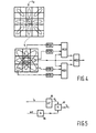
- FIG 4 is a schematic representation of the filtering performed in the conversion unit of an image processor according to the invention.
- the signal h k contains pixel-values b rs .
- c pq matrix-elements c pq .
- c 00 is the pixel-value b rs .
- MED0 median values of 0th order triplets of c pq are calculated (indicated by the boxes denoted MED0), the triplets extending in all four directions around c 00 in the matrix.
- the median values of the horizontal and vertical directions are combined with the central value c 00 to form a 1st order triplet.
- Another 1st order triplet is formed from both triplets relating to the diagonal directions in the matrix together with the central value c 00 .
- the boxes denoted MED1 indicate the calculation of the 1st order median values.
- a 2nd order triplet is finally formed (in the box MED2) from the median values of the 1st order triplets together with the central value c 00 .
- the median value of the 2nd order triplet is finally employed as the pixel-value d rs of the position (r,s) in the filtered high-pass frequency band image h k .
- the computation shown here amounts to a cascade of simple medians.
- the cascade median filtering replace the grey value c 00 in the centre if it is an extremum in each of the four directions tested by the median filtering. If in any direction this is not the case, for instance when the centre grey level is part of a brightness ramp with the adjacent averages from that direction, the centre grey level is considered to be a signal and preserved.
- the cascade median filtering shown in the example only requires eight simple averaging operations which may be performed each as the sum of two pixel-values followed by a bit shift and seven times computing a median value. It is noted that the filtering includes computations involving only a finite number, here three, of pixel-values b rs of the high-pass frequency band image, this feature represents the finite impulse response nature of the filtering.
- the cascade medium filtering outputs the central value C 00 is appears to be advantageous to replace that output by the average of the central value and values of sunwinding matrix elements C pq that differ at most predetermined value from the central value. In this way a further reduction of noise is achieved. Further, contrast is enhanced by forming said average latering into account only sunwinding matrix elements having a large value than the central value in case the central value exceeds a preset boundary value.
- the processing of the high-pass frequency-band image is preferably modified in that c 0,-1 and c 01 are not evaluated and the first order median is only evaluated for the vertical and the two diagonal directions, i.e. for the directions not parallel to the image lines. Subsequently, the result of the 0th order median MED0 for the vertical direction is directly fed onto the 2nd order median filter MED2.
- FIG. 5 is a diagrammatic representation of an embodiment of one of the threshold determinators 80,81,82 of the image processor according to the invention.
- Each threshold determinator comprises a look-up table (LUT) 85 in which expected standard deviations as a function of the signal level of the input image are stored, for the resolution level at issue. The expected standard deviation are stored e.g. in a tabular form.
- the low-pass frequency-band image signal l k of the resolution level at issue is supplied to the look-up table 85.
- an expected standard deviation level ⁇ k for the k-th resolution level is supplied by the look-up table 85.
- the expected standard deviation may also be multiplied by an external scale factor to account for external influences on the noise level.
- an x-ray dose employed to generate the input image signal is a parameter on which the noise level is dependent.
- a scale selector 86 is provided which outputs an appropriate scale-factor Sc in dependence of an external signal.
- the multiplicator 87 supplies the threshold-value T k for the resolution level at issue. So as to take into account the effect of the decomposition into the resolution level at issue on the noise level, separate look-up tables are provided at each resolution level.
- FIG. 6 is a diagrammatic representation of a further embodiment of a threshold determinator of an image processor according to the invention.
- a common look-up table 181 is provided containing expected standard deviations ⁇ k in dependence of pixel-values of the signal l k .
- the look-up table is arranged to communicate with the respective threshold determinators via a bus 182.
- the expected standard deviation pertaining to the average grey level is supplied to the multiplicator 87,
- the multiplicator 87 multiplies the expected standard deviation level ⁇ k by the appropriate scale factor so as to take into account the effect of the resolution level at issue on the noise level.
- a scale factor value ⁇ k associated with the respective resolution level is stored in a memory unit 183.
- the expected standard deviation may also be multiplied by an external scale factor to account for external influences on the noise level in the same way as explained with respect to Figure 5.
- the threshold-value T k for the k-th resolution level is supplied at the output of the multiplicator 87.
- FIG. 7 is a schematic representation of an x-ray examination apparatus provided with an image processor according to the invention.
- the x-ray examination apparatus 11 comprises an x-ray source 12 for irradiating an object 13, for example a patient who is to be radiologically examined, with an x-ray beam 14. Because of local variations of the x-ray absorption in the patient an x-ray shadow image is formed on an x-ray sensitive face 15 of an x-ray detector 16. An electronic image signal is derived from the x-ray image by the x-ray detector.
- the x-ray detector comprises an x-ray image intensifier 17 having an entrance section 18 which incorporates the x-ray sensitive face 15.
- the x-radiation incident on the entrance section 18 is converted in an image carrying electron beam which generates a light-optical image on the exit window 19.
- the entrance section includes the x-ray sensitive face, having the form of a scintillator screen 30, and a photocathode 31.
- the incident x-rays are converted in the scintillator screen into e.g. blue or ultraviolet light for which the photocathode 31 is sensitive.
- the electron beam 32 generated by the photocathode 31 is imaged by an electron-optical system 32 onto a phosphor screen 33 that is disposed on the exit window 19.
- the electron optical system includes the photocathode 31, a hollow anode 34 and a number of electrodes 35.
- a camera 20 is arranged to pick-up the light-optical image; to that end an optical coupling 21, e.g. a lens system, is provided to optically couple the camera 21 to the exit window 19.
- the electronic image signal at the output of the camera is supplied as the input image signal a 0 to the image processor 1 according to the invention.
- the output signal a ⁇ 0 represents a filtered output image in which noise is substantially reduced while small details are preserved. In practice a noise reduction of 4-5dB appears to be achieved. Therefore, the filtered output image has a high diagnostic quality even when a low x-ray dose is employed.
Claims (9)
- Bildverarbeitungsverfahren, das die folgenden Schritte umfasst:Aufteilen eines Eingangsbildes in mehrere Frequenzbandbilder mit Hilfe eines mehrfachauflösenden Zerlegungsverfahrens,Verarbeiten der einzelnen Frequenzbandbilder zum Ableiten verarbeiteter Frequenzbandbilder,Verarbeiten einschließlich Filterung der Frequenzbandbilder, um gefilterte Frequenzbandbilder zu erhalten,
undDurchführen eines mehrfachauflösenden Syntheseverfahrens an den genannten verarbeiteten Frequenzbandbildern, um ein gefiltertes Ausgangsbild zu schaffen,
dadurch gekennzeichnet, dassdie Filterung eine Filterung von Anordnungswerten beinhaltet. - Bildverarbeitungsverfahren nach Anspruch 1, dadurch gekennzeichnet, dass die Filterung von Anordnungswerten eine Median-Hybrid-Filterung mit begrenztem Ansprechen auf einen Impuls ist.
- Bildverarbeitungsverfahren nach Anspruch 1 oder 2, dadurch gekennzeichnet, dass die Verarbeitung folgendes umfasst:Berechnen von Differenzen für entsprechende Pixel zwischen den Pixelwerten eines gefilterten Frequenzbandbildes und den Pixelwerten eines entsprechenden Frequenzbandbildes,Vergleichen der genannten Differenzen mit einem Schwellenwert undAbleiten eines verarbeiteten Frequenzbandbildes von den Pixelwerten des genannten gefilterten Frequenzbandbildes, für dessen Pixelwerte die genannte Differenz kleiner als der Schwellenwert ist, und von Pixelwerten des genannten Frequenzbandbildes, für dessen Pixelwerte die genannte Differenz größer als der Schwellenwert ist.
- Bildverarbeitungsverfahren nach Anspruch 3, dadurch gekennzeichnet, dass der Schwellenwert einstellbar ist.
- Bildverarbeitungsverfahren nach Anspruch 4, wobei das Eingangsbild von einem Röntgenbild abgeleitet wird, das durch Bestrahlung eines Gegenstandes mit einem Röntgenstrahlenbündel gebildet wird, dadurch gekennzeichnet, dass der Schwellenwert von der Röntgenstrahlendosis abgeleitet wird.
- Bildverarbeitungsverfahren nach einem der vorhergehenden Ansprüche,
dadurch gekennzeichnet, dassdas Eingangsbild Teilbilder enthält, wobei die Bildzeilen separater Teilbilder alternierende Bildzeilen des Eingangsbildes bilden, und dassdie Filterung in Richtungen erfolgt, die nicht parallel zu den Bildzeilen des Eingangsbildes verlaufen. - Bildprozessor (1), der folgendes umfasst:eine Zerlegungseinheit (2) zum Aufteilen eines Eingangsbildsignals in mehrere Frequenzband-Bildsignale,eine Konvertierungseinheit (3) zum Verarbeiten der Frequenzband-Bildsignale, wobei die Konvertierungseinheit (3) ein Filter (40, 41, 42) zum Filtern der genannten Frequenzband-Bildsignale enthält, um verarbeitete Frequenzband-Bildsignale zu schaffen,einen Synthesizer (5) zum Bilden eines gefilterten Ausgangsbildsignals aus den genannten verarbeiteten Frequenzband-Bildsignalen,
dadurch gekennzeichnet, dassdas Filter ein Anordnungswertefilter umfasst. - Bildprozessor nach Anspruch 7, dadurch gekennzeichnet, dass die Konvertierungseinheit (3) folgendes umfasst:eine arithmetische Recheneinheit (50, 51, 52), die so ausgelegt ist, dass siePixelwerte der Frequenzband-Bildsignale und Pixelwerte der entsprechenden gefilterten Frequenzband-Bildsignale empfängt undDifferenzen zwischen den genannten Pixelwerten der Frequenzband-Bildsignale und den genannten Pixelwerten der entsprechenden gefilterten Frequenzband-Bildsignale berechnet,einen Komparator zum Vergleichen der genannten Differenzen mit einem Schwellenwert,eine Auswahleinheit zum Auswählen der Pixelwerte der gefilterten Frequenzband-Bildsignale, deren Differenz kleiner als der Schwellenwert ist, und zum Bilden eines verarbeiteten Frequenzbandbildes aus den ausgewählten Pixelwerten.
- Röntgenapparat, der folgendes umfasst:dadurch gekennzeichnet, dasseine Röntgenstrahlenquelle zum Bestrahlen eines Gegenstandes mit einem Röntgenstrahlenbündel, um ein Röntgenbild zu schaffen,einen Röntgendetektor, der der Röntgenstrahlenquelle gegenüberliegt, zum Ausgeben eines elektronischen Bildsignals aus dem Röntgenbild,
der Röntgenapparat mit einem Bildprozessor nach Anspruch 7 oder 8 ausgerüstet ist und dessen Eingang mit dem Ausgang des Röntgendetektors verbunden ist.
Priority Applications (1)
| Application Number | Priority Date | Filing Date | Title |
|---|---|---|---|
| EP96915123A EP0777891B1 (de) | 1995-06-23 | 1996-05-31 | Bildverarbeitungsverfahren zur rauschverminderung |
Applications Claiming Priority (4)
| Application Number | Priority Date | Filing Date | Title |
|---|---|---|---|
| EP95201718 | 1995-06-23 | ||
| EP95201718 | 1995-06-23 | ||
| EP96915123A EP0777891B1 (de) | 1995-06-23 | 1996-05-31 | Bildverarbeitungsverfahren zur rauschverminderung |
| PCT/IB1996/000534 WO1997001153A1 (en) | 1995-06-23 | 1996-05-31 | Image processing for noise reduction |
Publications (2)
| Publication Number | Publication Date |
|---|---|
| EP0777891A1 EP0777891A1 (de) | 1997-06-11 |
| EP0777891B1 true EP0777891B1 (de) | 2001-10-17 |
Family
ID=8220414
Family Applications (1)
| Application Number | Title | Priority Date | Filing Date |
|---|---|---|---|
| EP96915123A Expired - Lifetime EP0777891B1 (de) | 1995-06-23 | 1996-05-31 | Bildverarbeitungsverfahren zur rauschverminderung |
Country Status (5)
| Country | Link |
|---|---|
| US (1) | US5708693A (de) |
| EP (1) | EP0777891B1 (de) |
| JP (1) | JP3976337B2 (de) |
| DE (1) | DE69615994T2 (de) |
| WO (1) | WO1997001153A1 (de) |
Cited By (1)
| Publication number | Priority date | Publication date | Assignee | Title |
|---|---|---|---|---|
| US7317841B2 (en) | 2003-12-22 | 2008-01-08 | Ge Medical Systems Global Technology Company, Llc | System and method for image noise reduction using a minimal error spatiotemporal recursive filter |
Families Citing this family (45)
| Publication number | Priority date | Publication date | Assignee | Title |
|---|---|---|---|---|
| US5818900A (en) * | 1997-02-25 | 1998-10-06 | Infimed, Inc. | Image spot noise reduction employing rank order |
| US6314102B1 (en) | 1997-07-10 | 2001-11-06 | Alcatel | Telecommunications system for providing both narrowband and broadband services to subscribers |
| US6804403B1 (en) * | 1998-07-15 | 2004-10-12 | Digital Accelerator Corporation | Region-based scalable image coding |
| RU2150146C1 (ru) * | 1998-09-03 | 2000-05-27 | Семенченко Михаил Григорьевич | Способ обработки изображения |
| JP2003517911A (ja) * | 1999-12-20 | 2003-06-03 | コーニンクレッカ フィリップス エレクトロニクス エヌ ヴィ | 自由に傾斜制御可能なmri装置 |
| EP1223553A3 (de) * | 2000-10-17 | 2003-09-24 | Fuji Photo Film Co., Ltd. | Rauschunterdrückungsvorrichtung durch Anpassen der Filtercharakteristik an das Eingangsbildsignal abhängig von seinen Merkmalen |
| JP3651387B2 (ja) * | 2000-11-22 | 2005-05-25 | 日産自動車株式会社 | 白線検出装置 |
| JP3833177B2 (ja) * | 2000-11-30 | 2006-10-11 | キヤノン株式会社 | 画像処理装置、画象処理方法、記憶媒体及びプログラム |
| US20020076116A1 (en) * | 2000-12-15 | 2002-06-20 | Xerox Corporation | Fast implementation of homomorphic filters for image enhancement |
| US6931351B2 (en) * | 2001-04-20 | 2005-08-16 | International Business Machines Corporation | Decision making in classification problems |
| ATE373287T1 (de) * | 2001-05-16 | 2007-09-15 | Koninkl Philips Electronics Nv | Computertomographiesystem mit filterung |
| US6856702B2 (en) * | 2001-06-28 | 2005-02-15 | Andrew C. Gallagher | System and method for selecting an image processing path using estimated appearance of noise |
| US7431841B2 (en) * | 2001-11-13 | 2008-10-07 | Metanomics Gmbh & Co. Kgaa | Method for the extraction of components made from organic material |
| US7212689B2 (en) * | 2002-11-06 | 2007-05-01 | D. Darian Muresan | Fast edge directed polynomial interpolation |
| US7275058B2 (en) * | 2003-02-18 | 2007-09-25 | Seiko Epson Corporation | Method and system for finding a k order statistic in a union of sorted sets |
| DE10329608A1 (de) | 2003-07-01 | 2005-02-03 | Bts Media Solutions Gmbh | Verringerung von Rundungsfehlern bei der Bearbeitung digitaler Bilddaten |
| JP2005064706A (ja) * | 2003-08-08 | 2005-03-10 | Shimadzu Corp | 放射線撮像装置および放射線検出信号処理方法 |
| JP4651379B2 (ja) * | 2003-12-26 | 2011-03-16 | 富士フイルム株式会社 | 超音波画像処理装置及び超音波画像処理方法、並びに、超音波画像処理プログラム |
| US7945111B2 (en) * | 2004-12-20 | 2011-05-17 | Nikon Corporation | Image processing method for adaptively filtering image data |
| JP4709584B2 (ja) * | 2004-12-24 | 2011-06-22 | 富士フイルム株式会社 | 超音波診断装置、および超音波断層画像の生成方法、並びに超音波断層画像の生成プログラム |
| US7660481B2 (en) * | 2005-11-17 | 2010-02-09 | Vital Images, Inc. | Image enhancement using anisotropic noise filtering |
| EP2003612A4 (de) * | 2006-03-31 | 2010-10-13 | Nikon Corp | Bildverarbeitungsverfahren |
| JP5163489B2 (ja) * | 2006-03-31 | 2013-03-13 | 株式会社ニコン | 画像処理方法、画像処理プログラム、および画像処理装置 |
| JP4859632B2 (ja) | 2006-11-15 | 2012-01-25 | 富士通セミコンダクター株式会社 | 画像処理装置及び画像処理方法 |
| DE102007046941B4 (de) * | 2007-09-28 | 2017-12-28 | Siemens Healthcare Gmbh | Verfahren zur Darstellung von medizinischen Bildern sowie Röntgendiagnostikeinrichtung |
| FR2924254B1 (fr) * | 2007-11-23 | 2010-01-01 | Gen Electric | Procede de traitement d'images en radioscopie interventionnelle |
| US8238687B1 (en) | 2008-01-09 | 2012-08-07 | Helwett-Packard Development Company, L.P. | Local contrast enhancement of images |
| DE102008011530B4 (de) | 2008-02-28 | 2012-05-03 | Carl Zeiss Sms Gmbh | Verfahren zum Bearbeiten eines Objekts mit miniaturisierten Strukturen |
| JP5693241B2 (ja) | 2008-02-28 | 2015-04-01 | カールツァイス エスエムエス ゲーエムベーハーCarl Zeiss SMS GmbH | 微細化構造を有する物体の加工方法 |
| DE102008011531B4 (de) | 2008-02-28 | 2011-12-08 | Carl Zeiss Sms Gmbh | Verfahren zum Bearbeiten eines Objekts mit miniaturisierten Strukturen |
| JP5249111B2 (ja) * | 2009-03-31 | 2013-07-31 | オリンパス株式会社 | 画像処理装置、方法、プログラム、及び撮像システム |
| WO2010140281A1 (ja) * | 2009-06-04 | 2010-12-09 | シャープ株式会社 | 信号処理装置、信号処理装置の制御方法、制御プログラム、および該制御プログラムを記録したコンピュータ読み取り可能な記録媒体 |
| US8219574B2 (en) * | 2009-06-22 | 2012-07-10 | Microsoft Corporation | Querying compressed time-series signals |
| WO2011061958A1 (ja) | 2009-11-17 | 2011-05-26 | シャープ株式会社 | 復号化装置、復号化装置の制御方法、伝送システム、および制御プログラムを記録したコンピュータ読み取り可能な記録媒体 |
| US8811765B2 (en) | 2009-11-17 | 2014-08-19 | Sharp Kabushiki Kaisha | Encoding device configured to generate a frequency component extraction signal, control method for an encoding device using the frequency component extraction signal, transmission system, and computer-readable recording medium having a control program recorded thereon |
| JP5669416B2 (ja) * | 2010-03-23 | 2015-02-12 | オリンパス株式会社 | 蛍光観察装置 |
| KR101689867B1 (ko) * | 2010-09-15 | 2016-12-27 | 삼성전자주식회사 | 영상을 처리하는 방법, 이를 수행하는 영상처리장치 및 의료영상시스템 |
| US20120154207A1 (en) * | 2010-12-21 | 2012-06-21 | Electronics And Telecommunications Research Institute | Apparatus and method for scanning image in image processing system |
| JP6164926B2 (ja) * | 2013-05-16 | 2017-07-19 | オリンパス株式会社 | ノイズ低減処理装置 |
| WO2016083248A1 (en) | 2014-11-24 | 2016-06-02 | Koninklijke Philips N.V. | Simulating dose increase by noise model based multi scale noise reduction |
| CN104580937B (zh) * | 2015-01-21 | 2017-06-27 | 中国科学院上海技术物理研究所 | 一种红外成像系统条纹噪声去除方法 |
| CN107106105B (zh) | 2015-09-16 | 2021-09-07 | 皇家飞利浦有限公司 | 用于物体的x射线成像装置 |
| CN110346786B (zh) * | 2018-11-08 | 2023-04-21 | 西安电子科技大学 | 用于空间碎片判别和去除的雷达回波信号处理方法 |
| CN110532918B (zh) * | 2019-08-21 | 2022-02-25 | 南京大学 | 基于时间序列遥感影像的离岸风电场时空属性确定方法 |
| CN113972914A (zh) | 2020-07-22 | 2022-01-25 | 睿生光电股份有限公司 | 处理电路以及取样电路的信号处理方法 |
Family Cites Families (4)
| Publication number | Priority date | Publication date | Assignee | Title |
|---|---|---|---|---|
| DE69213149T2 (de) * | 1991-10-10 | 1997-03-06 | Philips Electronics Nv | Röntgenbildverstärkerröhre |
| DE69331719T2 (de) * | 1992-06-19 | 2002-10-24 | Agfa Gevaert Nv | Verfahren und Vorrichtung zur Geräuschunterdrückung |
| EP0574969B1 (de) * | 1992-06-19 | 2002-03-20 | Agfa-Gevaert | Verfahren und Vorrichtung zur Geräuschunterdrückung |
| US5417215A (en) * | 1994-02-04 | 1995-05-23 | Long Island Jewish Medical Center | Method of tissue characterization by ultrasound |
-
1996
- 1996-05-31 WO PCT/IB1996/000534 patent/WO1997001153A1/en active IP Right Grant
- 1996-05-31 DE DE69615994T patent/DE69615994T2/de not_active Expired - Fee Related
- 1996-05-31 JP JP50369997A patent/JP3976337B2/ja not_active Expired - Lifetime
- 1996-05-31 EP EP96915123A patent/EP0777891B1/de not_active Expired - Lifetime
- 1996-06-20 US US08/671,123 patent/US5708693A/en not_active Expired - Fee Related
Cited By (1)
| Publication number | Priority date | Publication date | Assignee | Title |
|---|---|---|---|---|
| US7317841B2 (en) | 2003-12-22 | 2008-01-08 | Ge Medical Systems Global Technology Company, Llc | System and method for image noise reduction using a minimal error spatiotemporal recursive filter |
Also Published As
| Publication number | Publication date |
|---|---|
| EP0777891A1 (de) | 1997-06-11 |
| US5708693A (en) | 1998-01-13 |
| JP3976337B2 (ja) | 2007-09-19 |
| JPH10505443A (ja) | 1998-05-26 |
| DE69615994T2 (de) | 2002-06-06 |
| WO1997001153A1 (en) | 1997-01-09 |
| DE69615994D1 (de) | 2001-11-22 |
Similar Documents
| Publication | Publication Date | Title |
|---|---|---|
| EP0777891B1 (de) | Bildverarbeitungsverfahren zur rauschverminderung | |
| US5467380A (en) | X-ray examination apparatus and means for noise reduction for use in an x-ray examination apparatus | |
| JP4598507B2 (ja) | 最小誤差時空間再帰フィルタを使用する画像ノイズ低減のためのシステム及び方法 | |
| JP3193806B2 (ja) | ノイズ減少方法および装置 | |
| US6766064B1 (en) | Method and apparatus for performing a contrast based dynamic range management algorithm | |
| US6173084B1 (en) | Noise reduction in an image | |
| Dhawan et al. | Mammographic feature enhancement by computerized image processing | |
| EP0527525B1 (de) | Verfahren und Vorrichtung zur Kontrastverbesserung von Bildern | |
| EP0712092A1 (de) | Verfahren zur Bildverbesserung | |
| EP0962888A2 (de) | Verfahren zur Entfernung von Trennlinienartefakten in Röntgenbildern | |
| US6760401B2 (en) | Apparatus and method for processing of digital images | |
| US7233689B2 (en) | Method of processing images for digital subtraction angiography | |
| JP2001057677A (ja) | 画像処理方法および装置並びに記録媒体 | |
| EP0574969B1 (de) | Verfahren und Vorrichtung zur Geräuschunterdrückung | |
| US7149358B2 (en) | Method and system for improving contrast using multi-resolution contrast based dynamic range management | |
| US20040258325A1 (en) | Noise suppression processing method, apparatus and program | |
| EP0578311B1 (de) | Röntgendurchleuchtungsgerät mit Mitteln zur Rauschreduktion | |
| Paranjape | Fundamental enhancement techniques | |
| US6956977B2 (en) | Methods for improving contrast based dynamic range management | |
| Hoeppner et al. | Equalized contrast display processing for digital radiography | |
| EP2092484A1 (de) | Rauschverminderung bei einem bildsignal | |
| JPH10105701A (ja) | 放射線画像強調処理方法および装置 | |
| JPH09270004A (ja) | X線画像デジタル処理装置 | |
| WO2009065441A1 (en) | Method and arrangement in fluoroscopy and ultrasound systems | |
| WO2010018480A1 (en) | Combination of x-ray image acquisitions with various focal spot sizes to improve image quality |
Legal Events
| Date | Code | Title | Description |
|---|---|---|---|
| PUAI | Public reference made under article 153(3) epc to a published international application that has entered the european phase |
Free format text: ORIGINAL CODE: 0009012 |
|
| AK | Designated contracting states |
Kind code of ref document: A1 Designated state(s): BE DE FR GB NL |
|
| 17P | Request for examination filed |
Effective date: 19970709 |
|
| GRAG | Despatch of communication of intention to grant |
Free format text: ORIGINAL CODE: EPIDOS AGRA |
|
| 17Q | First examination report despatched |
Effective date: 20001211 |
|
| GRAG | Despatch of communication of intention to grant |
Free format text: ORIGINAL CODE: EPIDOS AGRA |
|
| GRAH | Despatch of communication of intention to grant a patent |
Free format text: ORIGINAL CODE: EPIDOS IGRA |
|
| GRAH | Despatch of communication of intention to grant a patent |
Free format text: ORIGINAL CODE: EPIDOS IGRA |
|
| GRAA | (expected) grant |
Free format text: ORIGINAL CODE: 0009210 |
|
| AK | Designated contracting states |
Kind code of ref document: B1 Designated state(s): BE DE FR GB NL |
|
| PG25 | Lapsed in a contracting state [announced via postgrant information from national office to epo] |
Ref country code: NL Free format text: LAPSE BECAUSE OF FAILURE TO SUBMIT A TRANSLATION OF THE DESCRIPTION OR TO PAY THE FEE WITHIN THE PRESCRIBED TIME-LIMIT Effective date: 20011017 |
|
| REF | Corresponds to: |
Ref document number: 69615994 Country of ref document: DE Date of ref document: 20011122 |
|
| REG | Reference to a national code |
Ref country code: GB Ref legal event code: IF02 |
|
| ET | Fr: translation filed | ||
| NLV1 | Nl: lapsed or annulled due to failure to fulfill the requirements of art. 29p and 29m of the patents act | ||
| PG25 | Lapsed in a contracting state [announced via postgrant information from national office to epo] |
Ref country code: GB Free format text: LAPSE BECAUSE OF NON-PAYMENT OF DUE FEES Effective date: 20020531 |
|
| PLBE | No opposition filed within time limit |
Free format text: ORIGINAL CODE: 0009261 |
|
| STAA | Information on the status of an ep patent application or granted ep patent |
Free format text: STATUS: NO OPPOSITION FILED WITHIN TIME LIMIT |
|
| 26N | No opposition filed | ||
| REG | Reference to a national code |
Ref country code: FR Ref legal event code: D6 |
|
| GBPC | Gb: european patent ceased through non-payment of renewal fee |
Effective date: 20020531 |
|
| PGFP | Annual fee paid to national office [announced via postgrant information from national office to epo] |
Ref country code: BE Payment date: 20070503 Year of fee payment: 12 |
|
| PGFP | Annual fee paid to national office [announced via postgrant information from national office to epo] |
Ref country code: DE Payment date: 20070713 Year of fee payment: 12 |
|
| PGFP | Annual fee paid to national office [announced via postgrant information from national office to epo] |
Ref country code: FR Payment date: 20070529 Year of fee payment: 12 |
|
| BERE | Be: lapsed |
Owner name: KONINKLIJKE *PHILIPS ELECTRONICS N.V. Effective date: 20080531 |
|
| REG | Reference to a national code |
Ref country code: FR Ref legal event code: ST Effective date: 20090119 |
|
| PG25 | Lapsed in a contracting state [announced via postgrant information from national office to epo] |
Ref country code: BE Free format text: LAPSE BECAUSE OF NON-PAYMENT OF DUE FEES Effective date: 20080531 |
|
| PG25 | Lapsed in a contracting state [announced via postgrant information from national office to epo] |
Ref country code: FR Free format text: LAPSE BECAUSE OF NON-PAYMENT OF DUE FEES Effective date: 20080602 Ref country code: DE Free format text: LAPSE BECAUSE OF NON-PAYMENT OF DUE FEES Effective date: 20081202 |