EP0777055A2 - Antriebseinheit für hydraulischen Verbraucher - Google Patents
Antriebseinheit für hydraulischen Verbraucher Download PDFInfo
- Publication number
- EP0777055A2 EP0777055A2 EP96117401A EP96117401A EP0777055A2 EP 0777055 A2 EP0777055 A2 EP 0777055A2 EP 96117401 A EP96117401 A EP 96117401A EP 96117401 A EP96117401 A EP 96117401A EP 0777055 A2 EP0777055 A2 EP 0777055A2
- Authority
- EP
- European Patent Office
- Prior art keywords
- pump
- power unit
- load
- actuators
- converter
- Prior art date
- Legal status (The legal status is an assumption and is not a legal conclusion. Google has not performed a legal analysis and makes no representation as to the accuracy of the status listed.)
- Withdrawn
Links
Images
Classifications
-
- F—MECHANICAL ENGINEERING; LIGHTING; HEATING; WEAPONS; BLASTING
- F15—FLUID-PRESSURE ACTUATORS; HYDRAULICS OR PNEUMATICS IN GENERAL
- F15B—SYSTEMS ACTING BY MEANS OF FLUIDS IN GENERAL; FLUID-PRESSURE ACTUATORS, e.g. SERVOMOTORS; DETAILS OF FLUID-PRESSURE SYSTEMS, NOT OTHERWISE PROVIDED FOR
- F15B21/00—Common features of fluid actuator systems; Fluid-pressure actuator systems or details thereof, not covered by any other group of this subclass
- F15B21/14—Energy-recuperation means
-
- B—PERFORMING OPERATIONS; TRANSPORTING
- B66—HOISTING; LIFTING; HAULING
- B66F—HOISTING, LIFTING, HAULING OR PUSHING, NOT OTHERWISE PROVIDED FOR, e.g. DEVICES WHICH APPLY A LIFTING OR PUSHING FORCE DIRECTLY TO THE SURFACE OF A LOAD
- B66F9/00—Devices for lifting or lowering bulky or heavy goods for loading or unloading purposes
- B66F9/06—Devices for lifting or lowering bulky or heavy goods for loading or unloading purposes movable, with their loads, on wheels or the like, e.g. fork-lift trucks
- B66F9/075—Constructional features or details
- B66F9/20—Means for actuating or controlling masts, platforms, or forks
- B66F9/22—Hydraulic devices or systems
-
- F—MECHANICAL ENGINEERING; LIGHTING; HEATING; WEAPONS; BLASTING
- F15—FLUID-PRESSURE ACTUATORS; HYDRAULICS OR PNEUMATICS IN GENERAL
- F15B—SYSTEMS ACTING BY MEANS OF FLUIDS IN GENERAL; FLUID-PRESSURE ACTUATORS, e.g. SERVOMOTORS; DETAILS OF FLUID-PRESSURE SYSTEMS, NOT OTHERWISE PROVIDED FOR
- F15B11/00—Servomotor systems without provision for follow-up action; Circuits therefor
- F15B11/02—Systems essentially incorporating special features for controlling the speed or actuating force of an output member
-
- F—MECHANICAL ENGINEERING; LIGHTING; HEATING; WEAPONS; BLASTING
- F15—FLUID-PRESSURE ACTUATORS; HYDRAULICS OR PNEUMATICS IN GENERAL
- F15B—SYSTEMS ACTING BY MEANS OF FLUIDS IN GENERAL; FLUID-PRESSURE ACTUATORS, e.g. SERVOMOTORS; DETAILS OF FLUID-PRESSURE SYSTEMS, NOT OTHERWISE PROVIDED FOR
- F15B2211/00—Circuits for servomotor systems
- F15B2211/20—Fluid pressure source, e.g. accumulator or variable axial piston pump
- F15B2211/205—Systems with pumps
- F15B2211/20507—Type of prime mover
- F15B2211/20515—Electric motor
-
- F—MECHANICAL ENGINEERING; LIGHTING; HEATING; WEAPONS; BLASTING
- F15—FLUID-PRESSURE ACTUATORS; HYDRAULICS OR PNEUMATICS IN GENERAL
- F15B—SYSTEMS ACTING BY MEANS OF FLUIDS IN GENERAL; FLUID-PRESSURE ACTUATORS, e.g. SERVOMOTORS; DETAILS OF FLUID-PRESSURE SYSTEMS, NOT OTHERWISE PROVIDED FOR
- F15B2211/00—Circuits for servomotor systems
- F15B2211/20—Fluid pressure source, e.g. accumulator or variable axial piston pump
- F15B2211/205—Systems with pumps
- F15B2211/2053—Type of pump
- F15B2211/20569—Type of pump capable of working as pump and motor
-
- F—MECHANICAL ENGINEERING; LIGHTING; HEATING; WEAPONS; BLASTING
- F15—FLUID-PRESSURE ACTUATORS; HYDRAULICS OR PNEUMATICS IN GENERAL
- F15B—SYSTEMS ACTING BY MEANS OF FLUIDS IN GENERAL; FLUID-PRESSURE ACTUATORS, e.g. SERVOMOTORS; DETAILS OF FLUID-PRESSURE SYSTEMS, NOT OTHERWISE PROVIDED FOR
- F15B2211/00—Circuits for servomotor systems
- F15B2211/40—Flow control
- F15B2211/405—Flow control characterised by the type of flow control means or valve
- F15B2211/40515—Flow control characterised by the type of flow control means or valve with variable throttles or orifices
-
- F—MECHANICAL ENGINEERING; LIGHTING; HEATING; WEAPONS; BLASTING
- F15—FLUID-PRESSURE ACTUATORS; HYDRAULICS OR PNEUMATICS IN GENERAL
- F15B—SYSTEMS ACTING BY MEANS OF FLUIDS IN GENERAL; FLUID-PRESSURE ACTUATORS, e.g. SERVOMOTORS; DETAILS OF FLUID-PRESSURE SYSTEMS, NOT OTHERWISE PROVIDED FOR
- F15B2211/00—Circuits for servomotor systems
- F15B2211/40—Flow control
- F15B2211/415—Flow control characterised by the connections of the flow control means in the circuit
- F15B2211/41554—Flow control characterised by the connections of the flow control means in the circuit being connected to a return line and a directional control valve
-
- F—MECHANICAL ENGINEERING; LIGHTING; HEATING; WEAPONS; BLASTING
- F15—FLUID-PRESSURE ACTUATORS; HYDRAULICS OR PNEUMATICS IN GENERAL
- F15B—SYSTEMS ACTING BY MEANS OF FLUIDS IN GENERAL; FLUID-PRESSURE ACTUATORS, e.g. SERVOMOTORS; DETAILS OF FLUID-PRESSURE SYSTEMS, NOT OTHERWISE PROVIDED FOR
- F15B2211/00—Circuits for servomotor systems
- F15B2211/40—Flow control
- F15B2211/45—Control of bleed-off flow, e.g. control of bypass flow to the return line
-
- F—MECHANICAL ENGINEERING; LIGHTING; HEATING; WEAPONS; BLASTING
- F15—FLUID-PRESSURE ACTUATORS; HYDRAULICS OR PNEUMATICS IN GENERAL
- F15B—SYSTEMS ACTING BY MEANS OF FLUIDS IN GENERAL; FLUID-PRESSURE ACTUATORS, e.g. SERVOMOTORS; DETAILS OF FLUID-PRESSURE SYSTEMS, NOT OTHERWISE PROVIDED FOR
- F15B2211/00—Circuits for servomotor systems
- F15B2211/50—Pressure control
- F15B2211/505—Pressure control characterised by the type of pressure control means
- F15B2211/50509—Pressure control characterised by the type of pressure control means the pressure control means controlling a pressure upstream of the pressure control means
- F15B2211/50518—Pressure control characterised by the type of pressure control means the pressure control means controlling a pressure upstream of the pressure control means using pressure relief valves
-
- F—MECHANICAL ENGINEERING; LIGHTING; HEATING; WEAPONS; BLASTING
- F15—FLUID-PRESSURE ACTUATORS; HYDRAULICS OR PNEUMATICS IN GENERAL
- F15B—SYSTEMS ACTING BY MEANS OF FLUIDS IN GENERAL; FLUID-PRESSURE ACTUATORS, e.g. SERVOMOTORS; DETAILS OF FLUID-PRESSURE SYSTEMS, NOT OTHERWISE PROVIDED FOR
- F15B2211/00—Circuits for servomotor systems
- F15B2211/50—Pressure control
- F15B2211/515—Pressure control characterised by the connections of the pressure control means in the circuit
- F15B2211/5156—Pressure control characterised by the connections of the pressure control means in the circuit being connected to a return line and a directional control valve
-
- F—MECHANICAL ENGINEERING; LIGHTING; HEATING; WEAPONS; BLASTING
- F15—FLUID-PRESSURE ACTUATORS; HYDRAULICS OR PNEUMATICS IN GENERAL
- F15B—SYSTEMS ACTING BY MEANS OF FLUIDS IN GENERAL; FLUID-PRESSURE ACTUATORS, e.g. SERVOMOTORS; DETAILS OF FLUID-PRESSURE SYSTEMS, NOT OTHERWISE PROVIDED FOR
- F15B2211/00—Circuits for servomotor systems
- F15B2211/60—Circuit components or control therefor
- F15B2211/63—Electronic controllers
- F15B2211/6303—Electronic controllers using input signals
- F15B2211/6333—Electronic controllers using input signals representing a state of the pressure source, e.g. swash plate angle
-
- F—MECHANICAL ENGINEERING; LIGHTING; HEATING; WEAPONS; BLASTING
- F15—FLUID-PRESSURE ACTUATORS; HYDRAULICS OR PNEUMATICS IN GENERAL
- F15B—SYSTEMS ACTING BY MEANS OF FLUIDS IN GENERAL; FLUID-PRESSURE ACTUATORS, e.g. SERVOMOTORS; DETAILS OF FLUID-PRESSURE SYSTEMS, NOT OTHERWISE PROVIDED FOR
- F15B2211/00—Circuits for servomotor systems
- F15B2211/60—Circuit components or control therefor
- F15B2211/63—Electronic controllers
- F15B2211/6303—Electronic controllers using input signals
- F15B2211/6346—Electronic controllers using input signals representing a state of input means, e.g. joystick position
-
- F—MECHANICAL ENGINEERING; LIGHTING; HEATING; WEAPONS; BLASTING
- F15—FLUID-PRESSURE ACTUATORS; HYDRAULICS OR PNEUMATICS IN GENERAL
- F15B—SYSTEMS ACTING BY MEANS OF FLUIDS IN GENERAL; FLUID-PRESSURE ACTUATORS, e.g. SERVOMOTORS; DETAILS OF FLUID-PRESSURE SYSTEMS, NOT OTHERWISE PROVIDED FOR
- F15B2211/00—Circuits for servomotor systems
- F15B2211/70—Output members, e.g. hydraulic motors or cylinders or control therefor
- F15B2211/705—Output members, e.g. hydraulic motors or cylinders or control therefor characterised by the type of output members or actuators
- F15B2211/7051—Linear output members
- F15B2211/7052—Single-acting output members
-
- F—MECHANICAL ENGINEERING; LIGHTING; HEATING; WEAPONS; BLASTING
- F15—FLUID-PRESSURE ACTUATORS; HYDRAULICS OR PNEUMATICS IN GENERAL
- F15B—SYSTEMS ACTING BY MEANS OF FLUIDS IN GENERAL; FLUID-PRESSURE ACTUATORS, e.g. SERVOMOTORS; DETAILS OF FLUID-PRESSURE SYSTEMS, NOT OTHERWISE PROVIDED FOR
- F15B2211/00—Circuits for servomotor systems
- F15B2211/80—Other types of control related to particular problems or conditions
- F15B2211/88—Control measures for saving energy
Definitions
- the invention concerns a power unit for supplying hydraulic actuators with liquid under pressure, particularly suited to be used on self-propelled operating machines, such as fork-lifts and trolleys in general.
- the power units which supply the hydraulic actuators of self-propelled operating machines, particularly of fork-lift trucks comprise an accumulator battery which, by means of a converter, supplies an electric motor connected to a hydraulic pump which puts under pressure a liquid, preferably hydraulic oil.
- the hydraulic oil under pressure is sent, by means of one or more distributors, to the circuit which supplies the actuator or the actuators lifting and lowering the forks.
- Each of said distributors when set in one position conveys the oil from the pump to the actuators in order to obtain the lifting of the forks, while when set in another position it conveys the oil of the actuators to a collecting tank, so as to permit the lowering of the forks themselves.
- the suction pipe of the pump is also connected with the same oil collecting tank.
- the power units belonging to the described known type present a number of inconveniences.
- a first inconvenience is that, in order to change the speed of the descent movement of the forks and, therefore, of the load placed on them, it is necessary to use proper flow regulators.
- a second inconvenience is that the pump with which the power units belonging to the known type are equipped, is a pump having a constant capacity and in order to change the ascending speed of the forks and, therefore, of the load placed on the forks, a part of the quantity of oil which the pump sends to the actuator is conveyed through a discharge by-pass. It is easy to understand that this fact causes a waste of energy, sometimes a considerable one, since the hydraulic oil which is sent through the discharge by-pass, is oil taken at the delivery of the pump after it has been compressed to high pressure, which requires the exspenditure of some energy.
- a further inconvenience is also that the non-reversible pumps which are used in the power units belonging to the known type, are mostly gear pumps which present rather low performances and realize rather limited working pressures.
- the present invention proposes to overcome all the mentioned inconveniences and limitations.
- one of the purposes of the invention is to realize a power unit for supplying one or more actuators with liquid under pressure, particularly suited to be mounted on fork-lift trucks, which, except for unavoidable losses, permits to recover the potential energy owned by the load when it is lifted.
- a power unit for supplying one or more actuators with liquid under pressure which, in accordance with the main claim, comprises:
- said electric converter is a vectorial inverter with torque control suited to induce in said electric motor, consisting of an asynchronous motor, any torque value up the maximum torque suppliable, even when the shaft of said asynchronous motor is idle and said load is in a lifted position in relation to the ground.
- the use for the power unit according to the invention of a positive-displacement reversible pump permits a significant energy saving since during the lifting phase of the load the amount of oil put under pressure is directly proportional to the required lifting speed, while during the descending phase of the load said positive-displacement pump, operating by means of a motor, permits the recovery of the potential energy of the load.
- Such recoveries permit a better autonomy of operation of the battery as compared with equivalent systems belonging to the known type.
- the use of said positive-displacement reversible pump permits to obtain higher working pressures which imply reductions in the volumes of oil in circulation, reductions in the dimensions of the elements forming the circuit and much higher efficiencies as compared with equivalent systems belonging to the known technique.
- control torque vectorial in combination with the asynchronous motor and the reversible pump, permits to adjust the duty speed as far as zero speed, while keeping on supplying the required torque until it reaches the maximum value.
- the system presents a better handling, since all the speed adjustments can be done by acting directly on the inverter, for instance by operating a manipulator of the joy-stick type. Therefore, the power unit according to the invention, as compared with similar power units belonging to the known technique, presents, not only a better handling, but also the possibility of acting on the load with much more delicate and controlled manoeuvres.
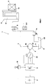
- the power unit according to the invention As can be observed in Fig. 1, the power unit according to the invention, indicated as a whole with 1, comprises:
- Another actuator 80 is arranged in connection with the delivery pipe 7 to indicate that more actuators can be supplied by the same delivery 7.
- said inverter is connected to a joy-stick type manipulator 12 which permits the adjustment of the asynchronous motor 30 and to an encoder 13 which controls the number of revolutions of the asynchronous motor 30.
- the system also comprises a valve of maximum pressure 14 which, in case of emergency, discharges in the collecting tank 5 the oil under pressure drawn from the delivery pipe 7.
- the inverter 3 which is used is a vectorial inverter with torque control belonging to the known type, suited to induce in said asynchronous motor 30 any torque value until the maximum suppliable torque is reached, even when the shaft of said asynchronous motor 30 is idle.
- said pump 4 is a reversible pump preferably of the piston type which, thanks to its reversibility, can also operate as a motor, as will be seen in the description given hereinafter, when it is supplied with liquid under pressure which enters through its delivery opening 42 and comes out of the suction opening 41.
- said pump drives into rotation the asynchronous motor 30 which operates as a generator and through the inverter 3 it supplies power to battery 2, re-charging it.
- Fig. 1 In order to describe the operation of the power unit according to the invention, reference is made to Fig. 1 wherein it can be observed that in the resting position the distributor 8 is shut and load 11, supported by the forks 10, is immobile in the position represented which corresponds, for instance, to the position on the ground.
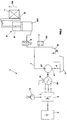
- the asynchronous motor 30 By acting on the joy-stick 12, the asynchronous motor 30 is driven into rotation and pump 4 sucks the oil 50 from tank 5 and through the delivery pipe 7 it sends it to each distributor 8. Should distributor 8, which supplies the actuator 9, be set in the open position, as can be observed in Fig. 2, actuator 9 is supplied and stem 91 with which it is equipped, comes out causing the lifting of the forks 10 and of load 11 placed on them, following direction 110.
- the distributor 8 could also not be present and the delivery pipe 7 could supply the actuator 9 directly. It is preferable, however, for the actuator 8 to be present, since by means of its opening, it is possible to choose the actuator to be supplied by acting on the joy-stick 12. It is possible to change the lifting speed of load 11 by acting appropriately on the joy-stick 12 by means of which the speeds of the asynchronous motor 30 and of the pump 4 connected to it and, therefore, the quantity of oil under pressure which supplies the actuator 9, are varied.
- any change of the lifting speed of load 11 is obtained by changing the number of revolutions of the asynchronous motor 30 and, consequently, of pump 4 connected with it.
- the quantity in the delivery pipe 7 which results to be proportional to the speed at which the forks 10 and load 11 placed on them are intended to be lifted. Therefore, all the energy that the asynchronous motor 30 supplies is used, except for the losses, to lift the load, contrary to what happens, instead, in the power units belonging to the known technique in which the electric motor and the pump supply a fixed quantity and the speed change for lifting the load is obtained by sending a part of the quantity taken at the delivery through a discharge by-pass, thereby suffering more or less important losses of energy.
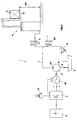
- inverter 3 In order to lower the load, it is necessary to act on inverter 3 by means of the joy-stick 12, by adjusting the resistant torque which the asynchronous motor 30 exerts on pump 4.
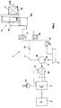
- the latter because it is of the reversible piston type, reverses its rotational direction, since it is supplied in correspondence with the delivery opening 42 by the flow 70 of oil which, as can be observed in Fig. 4, comes from the positive chamber 120 of the actuator 9, being pushed by piston 130 which is displaced downward following direction 140 because of the descent by gravity of load 11 placed on the forks 10.
- the suction opening 41 of the pump the oil is then discharged into tank 5.
- pump 4 acts then as a hydraulic motor and drives into rotation the asynchronous motor 30 which acts, therefore, as an electric power generator.
- the inverter 3 supplies battery 2, re-charging it, thus recovering, except for the inevitable losses, the potential energy owned by load 11 because of its being at height 150 from the ground.
- the power unit according to the invention also achieves the purpose of recovering as electric energy which is stored in the battery 2, the potential energy which load 11 loses when it descends, contrary to what happens in the power units belonging to the known technique in which all the potential energy owned by the load is dissipated in heat by the flow regulators which are used to adjust the descending speed of the load.
- the purpose of reducing the losses of energy while the load is being lifted is achieved.
- the capacity of the pump at the delivery is changed according to the speed with which the load is intended to be lifted.
- the purpose of recovering, except for unavoidable losses, the potential energy owned by the load when is in the lifted position is also achieved.
- the pressure which the load during its descent generates on the oil flowing back into the tank it is possible to make the pump to work as a hydraulic motor in order to drive into rotation the asynchronous motor.
- the latter by acting as a generator, re-charges the battery by means of the inverter.
- the power unit object of the present invention, can be also used on other types of operating machines, therefore, not only on fork-lift trucks.
- the power unit according to the invention may undergo changes suited to improve its operation or to make its manufacture less costly.
Applications Claiming Priority (3)
| Application Number | Priority Date | Filing Date | Title |
|---|---|---|---|
| IT95VI000172A IT1280604B1 (it) | 1995-11-02 | 1995-11-02 | Gruppo di potenza per l'alimentazione di attuatori idraulici |
| ITVI950172 | 1995-11-02 | ||
| US08/936,682 US6005360A (en) | 1995-11-02 | 1997-09-24 | Power unit for the supply of hydraulic actuators |
Publications (2)
| Publication Number | Publication Date |
|---|---|
| EP0777055A2 true EP0777055A2 (de) | 1997-06-04 |
| EP0777055A3 EP0777055A3 (de) | 1998-12-16 |
Family
ID=26332599
Family Applications (1)
| Application Number | Title | Priority Date | Filing Date |
|---|---|---|---|
| EP96117401A Withdrawn EP0777055A3 (de) | 1995-11-02 | 1996-10-30 | Antriebseinheit für hydraulischen Verbraucher |
Country Status (3)
| Country | Link |
|---|---|
| US (1) | US6005360A (de) |
| EP (1) | EP0777055A3 (de) |
| IT (1) | IT1280604B1 (de) |
Cited By (5)
| Publication number | Priority date | Publication date | Assignee | Title |
|---|---|---|---|---|
| EP0908413A2 (de) * | 1997-10-08 | 1999-04-14 | Still Wagner GmbH & Co. KG | Fluförderzeug mit einer Lastaufnahmevorrichtung und Verfahren zum Absenken der Lastaufnahmevorrichtung |
| WO2007051502A1 (de) * | 2005-11-02 | 2007-05-10 | Hydac Technology Gmbh | Hydraulikanlage |
| NL1035933C (en) * | 2008-09-15 | 2010-03-16 | Stertil Bv | System, lifting column and method for energy-efficient lifting and lowering a load. |
| CN104254693A (zh) * | 2012-03-30 | 2014-12-31 | 鲁卡斯液压有限公司 | 用于运行液压泵设备的方法以及液压泵设备 |
| US10180135B2 (en) | 2014-09-30 | 2019-01-15 | Artemis Intelligent Power Limited | Industrial system with synthetically commutated variable displacement fluid working machine |
Families Citing this family (27)
| Publication number | Priority date | Publication date | Assignee | Title |
|---|---|---|---|---|
| US6126401A (en) * | 1998-08-12 | 2000-10-03 | Computer Graphics Systems Development Corporation | Hybrid electric/hydraulic drive system |
| JP2000136806A (ja) * | 1998-11-04 | 2000-05-16 | Komatsu Ltd | 圧油のエネルギー回収装置および圧油のエネルギー回収・再生装置 |
| US6652239B2 (en) * | 2001-03-29 | 2003-11-25 | Kadant Inc. | Motor controller for a hydraulic pump with electrical regeneration |
| JP2004011168A (ja) * | 2002-06-04 | 2004-01-15 | Komatsu Ltd | 建設機械 |
| SE525159C2 (sv) * | 2002-06-05 | 2004-12-14 | Bt Ind Ab | Förfarande för att styra sänkningsrörelsen för en trucks luftcylinder |
| US20060090462A1 (en) * | 2003-11-14 | 2006-05-04 | Kazunori Yoshino | Energy regeneration system for working machinery |
| US7401464B2 (en) * | 2003-11-14 | 2008-07-22 | Caterpillar Inc. | Energy regeneration system for machines |
| US6945039B2 (en) * | 2003-11-14 | 2005-09-20 | Caterpillar Inc. | Power system and work machine using same |
| JP4667801B2 (ja) * | 2004-09-10 | 2011-04-13 | 日本輸送機株式会社 | 油圧システム及びこれを備えたフォークリフト |
| EP2217806B1 (de) * | 2007-11-09 | 2014-08-13 | Moog Inc. | Elektrohydraulisches stellglied zur steuerung des anstellwinkels einer windturbinenschaufel |
| US20110064706A1 (en) * | 2008-01-11 | 2011-03-17 | U.S. Nutraceuticals, Llc D/B/A Valensa International | Method of preventing, controlling and ameliorating urinary tract infections and supporting digestive health by using a synergistic cranberry derivative, a d-mannose composition and a proprietary probiotic blend |
| US7908852B2 (en) * | 2008-02-28 | 2011-03-22 | Caterpillar Inc. | Control system for recovering swing motor kinetic energy |
| US7980073B2 (en) * | 2008-05-08 | 2011-07-19 | Caterpillar Inc. | Hybrid system for a powertrain and hydraulic system |
| US20110056194A1 (en) * | 2009-09-10 | 2011-03-10 | Bucyrus International, Inc. | Hydraulic system for heavy equipment |
| US20110056192A1 (en) * | 2009-09-10 | 2011-03-10 | Robert Weber | Technique for controlling pumps in a hydraulic system |
| US8362629B2 (en) * | 2010-03-23 | 2013-01-29 | Bucyrus International Inc. | Energy management system for heavy equipment |
| US8626403B2 (en) | 2010-10-06 | 2014-01-07 | Caterpillar Global Mining Llc | Energy management and storage system |
| US8606451B2 (en) | 2010-10-06 | 2013-12-10 | Caterpillar Global Mining Llc | Energy system for heavy equipment |
| US8718845B2 (en) | 2010-10-06 | 2014-05-06 | Caterpillar Global Mining Llc | Energy management system for heavy equipment |
| WO2012051696A1 (en) | 2010-10-22 | 2012-04-26 | Tld Canada Inc. | Energy management system |
| US9803338B2 (en) | 2011-08-12 | 2017-10-31 | Eaton Corporation | System and method for recovering energy and leveling hydraulic system loads |
| EP2742186A2 (de) | 2011-08-12 | 2014-06-18 | Eaton Corporation | Verfahren und vorrichtung zur rückgewinnung von trägheitsenergie |
| US9190852B2 (en) | 2012-09-21 | 2015-11-17 | Caterpillar Global Mining Llc | Systems and methods for stabilizing power rate of change within generator based applications |
| EP2935907A1 (de) | 2012-12-19 | 2015-10-28 | Eaton Corporation | Regelsystem für ein hydrauliksystem und verfahren zur energierückgewinnung und zum lastenausgleich in diesem hydrauliksystem |
| DE102017106390A1 (de) * | 2017-03-24 | 2018-09-27 | Still Gmbh | Verfahren zum Betrieb einer Hydraulikanlage eines Flurförderzeugs |
| CN108975235B (zh) * | 2017-05-31 | 2020-11-06 | 北谷电子有限公司 | 升降装置动力系统及其控制方法 |
| WO2021112728A1 (en) * | 2019-12-05 | 2021-06-10 | Saab Ab | A self-contained electro-hydraulic linear actuator and a method for controlling the actuator |
Family Cites Families (8)
| Publication number | Priority date | Publication date | Assignee | Title |
|---|---|---|---|---|
| SE437861B (sv) * | 1983-02-03 | 1985-03-18 | Goran Palmers | Anordning vid medelst hydraul-cylinder drivna maskiner med en av en drivkella via en energiackumulatordriven pump |
| US4702076A (en) * | 1984-01-13 | 1987-10-27 | Dynamic Hydraulic Systems, Inc. | Hydraulically operated clam-shell device |
| JPH0780644B2 (ja) * | 1990-03-16 | 1995-08-30 | 株式会社日立製作所 | 油圧エレベーター |
| JP2628397B2 (ja) * | 1990-04-25 | 1997-07-09 | 回生工業株式会社 | インバータ電源を用いた油圧エレベータの速度制御方法 |
| JP2877257B2 (ja) * | 1991-02-05 | 1999-03-31 | 三菱重工業株式会社 | 作業機械の制御装置 |
| DE4317782C2 (de) * | 1993-05-28 | 1996-01-18 | Jungheinrich Ag | Hydraulische Hubvorrichtung für batteriegetriebene Flurförderzeuge oder dergleichen |
| DE4402653C2 (de) * | 1994-01-29 | 1997-01-30 | Jungheinrich Ag | Hydraulische Hubvorrichtung für batteriebetriebene Flurförderzeuge |
| US5499694A (en) * | 1994-08-15 | 1996-03-19 | Stewart & Stevenson Power, Inc. | Self propelled passenger lift vehicle |
-
1995
- 1995-11-02 IT IT95VI000172A patent/IT1280604B1/it active IP Right Grant
-
1996
- 1996-10-30 EP EP96117401A patent/EP0777055A3/de not_active Withdrawn
-
1997
- 1997-09-24 US US08/936,682 patent/US6005360A/en not_active Expired - Fee Related
Non-Patent Citations (1)
| Title |
|---|
| None |
Cited By (10)
| Publication number | Priority date | Publication date | Assignee | Title |
|---|---|---|---|---|
| EP0908413A2 (de) * | 1997-10-08 | 1999-04-14 | Still Wagner GmbH & Co. KG | Fluförderzeug mit einer Lastaufnahmevorrichtung und Verfahren zum Absenken der Lastaufnahmevorrichtung |
| EP0908413A3 (de) * | 1997-10-08 | 2001-08-08 | Still Wagner GmbH & Co. KG | Fluförderzeug mit einer Lastaufnahmevorrichtung und Verfahren zum Absenken der Lastaufnahmevorrichtung |
| WO2007051502A1 (de) * | 2005-11-02 | 2007-05-10 | Hydac Technology Gmbh | Hydraulikanlage |
| JP2009515100A (ja) * | 2005-11-02 | 2009-04-09 | ハイダック テクノロジー ゲゼルシャフト ミット ベシュレンクテル ハフツング | 油圧ユニット |
| US7891181B2 (en) | 2005-11-02 | 2011-02-22 | Hydac Technology Gmbh | Hydraulic unit |
| NL1035933C (en) * | 2008-09-15 | 2010-03-16 | Stertil Bv | System, lifting column and method for energy-efficient lifting and lowering a load. |
| EP2163506A1 (de) | 2008-09-15 | 2010-03-17 | Stertil B.V. | System, Hubsäule und Verfahren zum energieeffizienten Heben und Senken einer Last |
| US8251184B2 (en) | 2008-09-15 | 2012-08-28 | Stertil B.V. | Hydraulic load lifter with energy recovery system |
| CN104254693A (zh) * | 2012-03-30 | 2014-12-31 | 鲁卡斯液压有限公司 | 用于运行液压泵设备的方法以及液压泵设备 |
| US10180135B2 (en) | 2014-09-30 | 2019-01-15 | Artemis Intelligent Power Limited | Industrial system with synthetically commutated variable displacement fluid working machine |
Also Published As
| Publication number | Publication date |
|---|---|
| US6005360A (en) | 1999-12-21 |
| EP0777055A3 (de) | 1998-12-16 |
| ITVI950172A0 (it) | 1995-11-02 |
| IT1280604B1 (it) | 1998-01-23 |
| ITVI950172A1 (it) | 1997-05-02 |
Similar Documents
| Publication | Publication Date | Title |
|---|---|---|
| US6005360A (en) | Power unit for the supply of hydraulic actuators | |
| EP0314660A1 (de) | Hydraulische Hebeeinrichtung | |
| KR930002505B1 (ko) | 유압식 승강장치 | |
| EP1242748B1 (de) | Arbeitsmaschine | |
| EP1288505A1 (de) | Hybridmaschine mit hydraulischem antrieb | |
| US4761954A (en) | Fork-lift system | |
| EP3483453B1 (de) | Elektrohydraulisches arbeitsfahrzeug mit energierückgewinnung | |
| CN102606549B (zh) | 液压节能系统及液压起重设备 | |
| CN105502234B (zh) | 可调速大推力液压升降台 | |
| CN108083116A (zh) | 一种用于起重机的液压控制系统 | |
| CN108383039A (zh) | 一种节能型步进式升降机构液压控制系统 | |
| CN1079073C (zh) | 高能效液压举升系统的控制方法 | |
| CN112368482B (zh) | 液压回路 | |
| SK10393A3 (en) | Device for saving of electrical energy of drive of hydraulic lift | |
| EP3358202A1 (de) | Hydraulikzylinderantriebsvorrichtung | |
| US11542967B2 (en) | Hydraulic system with an energy recovery circuit | |
| CN114934934A (zh) | 一种具有分段调速功能的势能回收系统 | |
| JPS62184206A (ja) | 電気−油圧変換式駆動装置 | |
| JPH075269B2 (ja) | 作業車両の油圧動力回収装置 | |
| JPS60154900A (ja) | 油圧発生装置 | |
| USRE32404E (en) | Elevator with power recovery | |
| JP2553978Y2 (ja) | 建設機械の原動機と油圧回路の制御装置 | |
| CN114483678B (zh) | 强夯机电液控制系统及强夯机 | |
| JP4840263B2 (ja) | 発電システム | |
| CN101955139B (zh) | 节能堆高机 |
Legal Events
| Date | Code | Title | Description |
|---|---|---|---|
| PUAI | Public reference made under article 153(3) epc to a published international application that has entered the european phase |
Free format text: ORIGINAL CODE: 0009012 |
|
| AK | Designated contracting states |
Kind code of ref document: A2 Designated state(s): DE ES FR GB |
|
| PUAL | Search report despatched |
Free format text: ORIGINAL CODE: 0009013 |
|
| AK | Designated contracting states |
Kind code of ref document: A3 Designated state(s): DE ES FR GB |
|
| 17P | Request for examination filed |
Effective date: 19990426 |
|
| 17Q | First examination report despatched |
Effective date: 20000518 |
|
| STAA | Information on the status of an ep patent application or granted ep patent |
Free format text: STATUS: THE APPLICATION HAS BEEN WITHDRAWN |
|
| 18W | Application withdrawn |
Withdrawal date: 20001206 |