EP0775868A1 - Gasbrenner für Aufwärmöfen für siderurgische Produkte - Google Patents
Gasbrenner für Aufwärmöfen für siderurgische Produkte Download PDFInfo
- Publication number
- EP0775868A1 EP0775868A1 EP96402273A EP96402273A EP0775868A1 EP 0775868 A1 EP0775868 A1 EP 0775868A1 EP 96402273 A EP96402273 A EP 96402273A EP 96402273 A EP96402273 A EP 96402273A EP 0775868 A1 EP0775868 A1 EP 0775868A1
- Authority
- EP
- European Patent Office
- Prior art keywords
- burner
- gas
- orifices
- nose
- passage
- Prior art date
- Legal status (The legal status is an assumption and is not a legal conclusion. Google has not performed a legal analysis and makes no representation as to the accuracy of the status listed.)
- Granted
Links
- 229910000831 Steel Inorganic materials 0.000 title claims description 18
- 239000010959 steel Substances 0.000 title claims description 18
- 238000003303 reheating Methods 0.000 title claims description 7
- 238000010438 heat treatment Methods 0.000 claims description 23
- 238000011144 upstream manufacturing Methods 0.000 claims description 4
- 239000007789 gas Substances 0.000 description 38
- VNWKTOKETHGBQD-UHFFFAOYSA-N methane Chemical compound C VNWKTOKETHGBQD-UHFFFAOYSA-N 0.000 description 16
- MWUXSHHQAYIFBG-UHFFFAOYSA-N Nitric oxide Chemical compound O=[N] MWUXSHHQAYIFBG-UHFFFAOYSA-N 0.000 description 9
- 239000003345 natural gas Substances 0.000 description 8
- 238000002485 combustion reaction Methods 0.000 description 7
- 230000005855 radiation Effects 0.000 description 5
- 239000000446 fuel Substances 0.000 description 3
- 239000000571 coke Substances 0.000 description 2
- 239000003517 fume Substances 0.000 description 2
- 239000000203 mixture Substances 0.000 description 2
- 238000005054 agglomeration Methods 0.000 description 1
- 230000002776 aggregation Effects 0.000 description 1
- QVGXLLKOCUKJST-UHFFFAOYSA-N atomic oxygen Chemical compound [O] QVGXLLKOCUKJST-UHFFFAOYSA-N 0.000 description 1
- 230000008033 biological extinction Effects 0.000 description 1
- 229910010293 ceramic material Inorganic materials 0.000 description 1
- 239000011248 coating agent Substances 0.000 description 1
- 238000000576 coating method Methods 0.000 description 1
- 239000000567 combustion gas Substances 0.000 description 1
- 230000032798 delamination Effects 0.000 description 1
- 239000003546 flue gas Substances 0.000 description 1
- 230000004907 flux Effects 0.000 description 1
- 239000002737 fuel gas Substances 0.000 description 1
- 230000003116 impacting effect Effects 0.000 description 1
- 238000004519 manufacturing process Methods 0.000 description 1
- 238000013021 overheating Methods 0.000 description 1
- 239000001301 oxygen Substances 0.000 description 1
- 229910052760 oxygen Inorganic materials 0.000 description 1
- 238000005096 rolling process Methods 0.000 description 1
- 238000000926 separation method Methods 0.000 description 1
- 239000000779 smoke Substances 0.000 description 1
Images
Classifications
-
- F—MECHANICAL ENGINEERING; LIGHTING; HEATING; WEAPONS; BLASTING
- F23—COMBUSTION APPARATUS; COMBUSTION PROCESSES
- F23D—BURNERS
- F23D14/00—Burners for combustion of a gas, e.g. of a gas stored under pressure as a liquid
- F23D14/20—Non-premix gas burners, i.e. in which gaseous fuel is mixed with combustion air on arrival at the combustion zone
- F23D14/22—Non-premix gas burners, i.e. in which gaseous fuel is mixed with combustion air on arrival at the combustion zone with separate air and gas feed ducts, e.g. with ducts running parallel or crossing each other
- F23D14/24—Non-premix gas burners, i.e. in which gaseous fuel is mixed with combustion air on arrival at the combustion zone with separate air and gas feed ducts, e.g. with ducts running parallel or crossing each other at least one of the fluids being submitted to a swirling motion
-
- F—MECHANICAL ENGINEERING; LIGHTING; HEATING; WEAPONS; BLASTING
- F23—COMBUSTION APPARATUS; COMBUSTION PROCESSES
- F23C—METHODS OR APPARATUS FOR COMBUSTION USING FLUID FUEL OR SOLID FUEL SUSPENDED IN A CARRIER GAS OR AIR
- F23C9/00—Combustion apparatus characterised by arrangements for returning combustion products or flue gases to the combustion chamber
- F23C9/006—Combustion apparatus characterised by arrangements for returning combustion products or flue gases to the combustion chamber the recirculation taking place in the combustion chamber
-
- F—MECHANICAL ENGINEERING; LIGHTING; HEATING; WEAPONS; BLASTING
- F23—COMBUSTION APPARATUS; COMBUSTION PROCESSES
- F23M—CASINGS, LININGS, WALLS OR DOORS SPECIALLY ADAPTED FOR COMBUSTION CHAMBERS, e.g. FIREBRIDGES; DEVICES FOR DEFLECTING AIR, FLAMES OR COMBUSTION PRODUCTS IN COMBUSTION CHAMBERS; SAFETY ARRANGEMENTS SPECIALLY ADAPTED FOR COMBUSTION APPARATUS; DETAILS OF COMBUSTION CHAMBERS, NOT OTHERWISE PROVIDED FOR
- F23M5/00—Casings; Linings; Walls
- F23M5/02—Casings; Linings; Walls characterised by the shape of the bricks or blocks used
- F23M5/025—Casings; Linings; Walls characterised by the shape of the bricks or blocks used specially adapted for burner openings
Definitions
- the present invention relates to a gas burner, of the type used in furnaces for heating steel products, such as slab ovens for example.
- These burners are high-power burners, supplied in particular with steel gas (mixed gas, coke oven gas for example), and are placed in the roof of the reheating furnaces.
- steel gas mixed gas, coke oven gas for example
- burners of this type which generally comprise several concentric channels for supplying combustible gas and air, opening at the level of the burner nose, downstream of which combustion occurs.
- burners of the “jet burner” type are known with very high gas ejection speed, greater than 100 meters per second.
- the air and the combustion gas burn in the combustion chamber of the burner, and at the outlet of the burner, there is hot smoke, the combustion being completed.
- This type of burner is commonly used in ovens requiring direct heating of the products, for example in coke agglomeration hoods, because the very high gas ejection speed makes it possible to heat a very localized area.
- Such a type of burner is not suitable for furnaces for heating steel products because the heating they provide is very localized direct heating. Their use would cause temperature heterogeneity on the product to be reheated with the significant risk of the appearance of black marks and the risk of causing problems during the subsequent rolling operation (in the case of reheating the slabs).
- burners called “flat flame” or so-called “flat flame”.
- the combustion air is brought into rotation around the gas supply.
- the flame due to the combustion of the air / gas mixture is generated downstream of the burner nose, in the burner, that is to say in the housing provided in the internal lining of the oven and in which the burner is inserted.
- This tulip-shaped workpiece allows the flame to be pressed against the walls of said worker and against the walls of the roof of the oven.
- This type of burner allowing indirect heating of the product by radiation from the roof of the oven, has a number of drawbacks.
- the weak impulse of gases in this type of burner leads to poor mixing of the fumes inside the furnace and thus a heterogeneity of temperatures between the roof of the furnace and the steel product to be heated.
- this type of burner by design, has a flared flat flame and therefore a certain black hole in the center of said flame, where it does not generate a flame. This phenomenon reinforces the problem of temperature heterogeneity.
- this type of burner is not multi-fuel. It is only intended to operate on steel gas and cannot be adapted to operate on natural gas.
- This type of burner requires a tulip-shaped burner, it is relatively expensive to operate because of the high cost of this type of burner. In addition, this type of workman is relatively fragile.
- this type of burner has a low thermal efficiency, in the sense of its capacity to generate a temperature rise in the oven, because the useful heating surface on the roof of the oven of each burner is relatively small.
- the flame due to the combustion of the air / gas mixture is generated downstream of the burner nose, in the opening, in the form of a ball.
- This type of burner has three series of orifices, a first for the passage of gas, a second for the passage of air, arranged in a circle around the orifices for the passage of gas, generating a short flame, with a length of l 'order of 2 meters, and a third series of orifices for the passage of air, located at the periphery, generating a long flame, with a length of the order of 4.5 meters.
- This type of burner is a burner for direct heating of steel products. It therefore has a drawback linked to this function, namely the heterogeneity of the temperatures at the level of the product to be heated, certainly less significant than in the case of "jet burners".
- the object of the present invention is to propose a burner combining the direct heating and indirect heating function by radiation of the roof of the oven, having a large latitude for adjusting the heating power, making it possible to generate a uniform temperature of the roof of the oven, can use both steel and natural gas, while not producing too much nitrogen oxide.
- the present invention also relates to an oven vault for heating steel products, characterized in that it comprises at least one housing 9, cylindrical with diameter D3, arranged in the internal lining of the oven vault, in which a burner is maintained according to the preceding claims, and in that the ratio between the diameter D2 of the crown of the orifices for the passage of air from the burner and the diameter D3 of the housing 9 is between 0.6 and 0.8, preferably equal at 0.68.
- the ratio between the diameter D3 of the housing arranged in the internal lining of the oven roof and the distance between the front surface of the burner nose and the oven roof is between 0.9 and 1, preferably equal to 0.95.
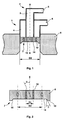
- the burner 1 comprises a box 2 for supplying combustible gas and air, formed by a central channel 3 for supplying the gas, oriented in the axial direction X of the burner, surrounded by an annular channel 4 for supplying d 'air.
- the burner 1 also includes a nose 7 also called a diffuser, generally made of a ceramic material.
- the nose 7 consists of a thick plate 8 which covers the axial ends of the different channels while ensuring the seal between them, and which is inserted in a housing 9, cylindrical with diameter D3, arranged in the internal coating of the roof of the oven, being held there by fixing means, not shown, on the wall of the oven.
- the upstream face of the burner nose 7 has a flat front surface 13, facing the interior of the furnace.
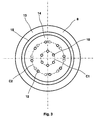
- the plate 8 of the burner nose 7 is traversed by a plurality of gas and air outlet orifices.
- the orifices 10, connected to the gas supply channel 3 are coaxial with the axial direction X of the burner.
- the plate 8 of the nose 7 of the burner is provided with six orifices 10, also distributed in a circle on the crown C1.
- the orifices 12, connected to the air supply channel 4 are made so that the axis of each orifice is situated in a plane parallel to the axial direction of the burner and tangent to the crown C2, and inclined in this plane, by an angle ⁇ with respect to said axial direction.
- the angle ⁇ is between 15 and 25 °.
- the orifices 12 are therefore oriented in a helix, so that the air flow which escapes therefrom has a rotational movement around the axis X of the burner, thus creating a swirling air flow causing a vacuum which sucks the gas flow.
- the plate 8 of the nose 7 of the burner is provided with eight orifices 12, also distributed in a circle on the crown C2.
- the nose 7 of the burner has a part 14 recessed towards the inside of the burner with respect to the front surface 13, substantially planar, perpendicular to the axis X of the burner, into which the orifices 10 for the passage of gas and the orifices open 12 for air passage, the recessed part 14 and the front surface 13 being connected to each other by a connecting surface 15.
- connection surface 15 between the front surface 13 and the recessed part 14 of the upstream face of the burner nose is substantially in the form of a truncated cone, the large base of which is located at the front surface 13.
- the angle ⁇ of the truncated cone of the connecting surface 15 is between 20 and 40 °, preferably equal to 30 °.
- the ratio D1 / D2 of the rings C1 and C2, respectively of the series of orifices 10 for the passage of gas and of the series of air passage openings is between 0.4 and 0.5.
- this ratio D1 / D2 is less than 0.4, the flame is of the "jet" type, directly impacting the product, and in the case of the use of natural gas, there is separation of the flame and risk of extinction . If this ratio is greater than 0.5, the flame is very short, disturbed, and the burner overheats, especially if natural gas is used.
- the ratio between the diameter D2 of the crown C2 of the series of air passage orifices 12 and the diameter D3 of the housing 9 arranged in the internal lining of the roof of the oven is between 0.6 and 0.8.
- this ratio D2 / D3 is less than 0.6, a soft, poorly directed flame is produced, sensitive to variations in the internal pressure of the furnace. If this ratio is greater than 0.8, the flame is an airplane nozzle type torch, it there is a strong delamination of the flame if natural gas is used, and at high flow the flame is blown for all types of gas.
- the ratio between the diameter D3 of the housing 9 fitted in the internal lining of the roof of the oven and the distance H between the front surface 13 of the burner nose and the roof of the oven is between 0.9 and 1.
- this D3 / H ratio is less than 0.9, there is internal overheating and too much NOx production when using steel gas. If this ratio is greater than 1, the flame is badly directed and the combustion is incomplete.
- This configuration allows the flame to develop in the housing 9 arranged in the roof of the oven. This flame is not directly pressed against the wall of the roof of the oven, but develops inside the oven in the form of a very obtuse angle cone, of the order of 160 to 170 °.
- the flame develops inside the oven more or less pressed against the wall of the roof of the oven.
- a ratio of diameters D1 / D2 equal to 0.40 or equal to 0.50 makes it possible to ensure that the burner will effectively combine the direct heating and indirect heating function by radiation from the roof of the oven.
- a D1 / D2 ratio of 0.43 is very close to ideal if a steel gas is used, but is not completely satisfactory if natural gas is used.
- a D1 / D2 ratio of 0.48 for example, is very close to ideal for natural gas, but causes sparks if a mixed gas is used at high flow rates and produces too much NOx.
- the ratio between the diameter D3 and the distance H is optimum when it is between 0.93 and 0.97, preferably equal to 0.95.
- Such a burner makes it possible to obtain heating of the furnace according to two combined modes, direct heating and indirect radiant heating, and this from a gas ejection speed equal to 40 meters per second.
- Such a burner can thus operate with a gas ejection speed of 40 to 100 meters per second, which gives it great latitude in adjusting the heating power, while ensuring a homogeneous vault temperature.
- Such a burner is multi-fuel, that is to say that it retains its properties regardless of the type of gas used, from natural gas to steel gas.
Landscapes
- Engineering & Computer Science (AREA)
- Chemical & Material Sciences (AREA)
- Combustion & Propulsion (AREA)
- Mechanical Engineering (AREA)
- General Engineering & Computer Science (AREA)
- Gas Burners (AREA)
- Pre-Mixing And Non-Premixing Gas Burner (AREA)
- Furnace Details (AREA)
Applications Claiming Priority (2)
| Application Number | Priority Date | Filing Date | Title |
|---|---|---|---|
| FR9513905 | 1995-11-23 | ||
| FR9513905A FR2741702B1 (fr) | 1995-11-23 | 1995-11-23 | Bruleur a gaz pour four de rechauffage de produits siderurgiques |
Publications (2)
| Publication Number | Publication Date |
|---|---|
| EP0775868A1 true EP0775868A1 (de) | 1997-05-28 |
| EP0775868B1 EP0775868B1 (de) | 1999-09-22 |
Family
ID=9484838
Family Applications (1)
| Application Number | Title | Priority Date | Filing Date |
|---|---|---|---|
| EP96402273A Expired - Lifetime EP0775868B1 (de) | 1995-11-23 | 1996-10-25 | Gasbrenner für Aufwärmöfen für siderurgische Produkte |
Country Status (5)
| Country | Link |
|---|---|
| EP (1) | EP0775868B1 (de) |
| AT (1) | ATE184978T1 (de) |
| DE (1) | DE69604366T2 (de) |
| ES (1) | ES2136955T3 (de) |
| FR (1) | FR2741702B1 (de) |
Cited By (6)
| Publication number | Priority date | Publication date | Assignee | Title |
|---|---|---|---|---|
| EP0823593A3 (de) * | 1996-08-05 | 1998-11-04 | The BOC Group plc | Emissionsarmer Wirbelbrenner |
| ES2159217A1 (es) * | 1998-05-14 | 2001-09-16 | Adiego Tomas Adiego | Dispositivo para evitar perdidas termicas de la corona de llamas de un quemador. |
| WO2003081136A1 (en) * | 2002-03-22 | 2003-10-02 | Danieli & C. Officine Meccaniche S.P.A. | Burner |
| WO2008070627A3 (en) * | 2006-12-04 | 2008-08-21 | Praxair Technology Inc | Combustion with variable oxidant low nox burner |
| US20100139324A1 (en) * | 2007-04-12 | 2010-06-10 | Saint- Gobain Isover | Internal combustion burner |
| EP3350513A1 (de) * | 2015-07-31 | 2018-07-25 | Nuvera Fuel Cells, LLC | Brenneranordnung mit geringen nox-emissionen |
Families Citing this family (1)
| Publication number | Priority date | Publication date | Assignee | Title |
|---|---|---|---|---|
| DE102008011567B4 (de) * | 2008-02-28 | 2010-01-28 | Corall, Paul, Dipl.-Ing. | Prüfeinrichtung zur Überprüfung der Funktionsfähigkeit von Rauchabzugsanlagen |
Citations (4)
| Publication number | Priority date | Publication date | Assignee | Title |
|---|---|---|---|---|
| FR2193464A5 (de) * | 1972-07-21 | 1974-02-15 | Airco Inc | |
| FR2532405A1 (fr) * | 1982-08-25 | 1984-03-02 | Air Liquide | Procede et dispositif d'allumage electrique d'un bruleur oxycombustible |
| EP0495690A1 (de) * | 1991-01-16 | 1992-07-22 | Sollac | Mischer von Luft und Verbrennungsgas für Gasbrenner von Industrieöfen |
| EP0674135A1 (de) * | 1994-03-24 | 1995-09-27 | Sollac S.A. | Gasbrenner für Industrieöfen |
-
1995
- 1995-11-23 FR FR9513905A patent/FR2741702B1/fr not_active Expired - Fee Related
-
1996
- 1996-10-25 DE DE69604366T patent/DE69604366T2/de not_active Expired - Fee Related
- 1996-10-25 ES ES96402273T patent/ES2136955T3/es not_active Expired - Lifetime
- 1996-10-25 EP EP96402273A patent/EP0775868B1/de not_active Expired - Lifetime
- 1996-10-25 AT AT96402273T patent/ATE184978T1/de not_active IP Right Cessation
Patent Citations (4)
| Publication number | Priority date | Publication date | Assignee | Title |
|---|---|---|---|---|
| FR2193464A5 (de) * | 1972-07-21 | 1974-02-15 | Airco Inc | |
| FR2532405A1 (fr) * | 1982-08-25 | 1984-03-02 | Air Liquide | Procede et dispositif d'allumage electrique d'un bruleur oxycombustible |
| EP0495690A1 (de) * | 1991-01-16 | 1992-07-22 | Sollac | Mischer von Luft und Verbrennungsgas für Gasbrenner von Industrieöfen |
| EP0674135A1 (de) * | 1994-03-24 | 1995-09-27 | Sollac S.A. | Gasbrenner für Industrieöfen |
Cited By (11)
| Publication number | Priority date | Publication date | Assignee | Title |
|---|---|---|---|---|
| EP0823593A3 (de) * | 1996-08-05 | 1998-11-04 | The BOC Group plc | Emissionsarmer Wirbelbrenner |
| ES2159217A1 (es) * | 1998-05-14 | 2001-09-16 | Adiego Tomas Adiego | Dispositivo para evitar perdidas termicas de la corona de llamas de un quemador. |
| WO2003081136A1 (en) * | 2002-03-22 | 2003-10-02 | Danieli & C. Officine Meccaniche S.P.A. | Burner |
| US7004408B2 (en) | 2002-03-22 | 2006-02-28 | Danieli & C. Officine Meccaniche S.P.A. | Burner |
| WO2008070627A3 (en) * | 2006-12-04 | 2008-08-21 | Praxair Technology Inc | Combustion with variable oxidant low nox burner |
| US7549858B2 (en) | 2006-12-04 | 2009-06-23 | Praxair Technology, Inc. | Combustion with variable oxidant low NOx burner |
| US7896647B2 (en) | 2006-12-04 | 2011-03-01 | Praxair Technology, Inc. | Combustion with variable oxidant low NOx burner |
| US20100139324A1 (en) * | 2007-04-12 | 2010-06-10 | Saint- Gobain Isover | Internal combustion burner |
| US9587822B2 (en) * | 2007-04-12 | 2017-03-07 | Saint-Gobain Isover | Internal combustion burner |
| EP3350513A1 (de) * | 2015-07-31 | 2018-07-25 | Nuvera Fuel Cells, LLC | Brenneranordnung mit geringen nox-emissionen |
| JP2018522200A (ja) * | 2015-07-31 | 2018-08-09 | ヌヴェラ・フュエル・セルズ,エルエルシー | NOx放出が低減されたバーナーアセンブリ |
Also Published As
| Publication number | Publication date |
|---|---|
| DE69604366T2 (de) | 2000-05-11 |
| ATE184978T1 (de) | 1999-10-15 |
| FR2741702A1 (fr) | 1997-05-30 |
| FR2741702B1 (fr) | 1997-12-26 |
| ES2136955T3 (es) | 1999-12-01 |
| DE69604366D1 (de) | 1999-10-28 |
| EP0775868B1 (de) | 1999-09-22 |
Similar Documents
| Publication | Publication Date | Title |
|---|---|---|
| EP0674135B2 (de) | Gasbrenner für Industrieöfen | |
| US5431559A (en) | Oxygen-fuel burner with staged oxygen supply | |
| CA2211769C (en) | Low emission swirl burner | |
| CA1253745A (fr) | Bruleur a charbon pulverise | |
| FR2581163A1 (fr) | Bruleur pour flamber des materiaux en acier | |
| EP0099828B1 (de) | Vorrichtung zur Verbrennung von brennbaren Fluiden mit Luftinduktion | |
| BE1015604A3 (fr) | Procede et dispositif pour augmenter la stabilite de la flamme dans les foyers au charbon pulverise. | |
| FR2616520A1 (fr) | Systeme a bruleur notamment a grande vitesse de sortie des gaz brules | |
| EP0775868B1 (de) | Gasbrenner für Aufwärmöfen für siderurgische Produkte | |
| CA2053457A1 (fr) | Procede de chauffe d'une enceinte thermique et bruleur | |
| EP0703410B1 (de) | Brenner mit einem Brennerstein und Verfahren zu dessen Verwendung | |
| EP0242249B1 (de) | Brenner mit niedriger Schadstoffemission im Abgas | |
| EP1702177A1 (de) | Verfahren zur abgestuften verbrennung mit optimierter einspritzung von primäroxidationsmittel | |
| EP0850883A2 (de) | Verfahren zur Herstellung von technischem Glas und Brenner zur Durchführung des Verfahrens | |
| CA1123285A (fr) | Procede de combustion d'un combustible liquide et bruleur pour sa mise en oeuvre | |
| EP0178198B1 (de) | Brenner mit vorheriger integrierter Mischung und integrierter Pilot-Flamme | |
| FR2780770A1 (fr) | Recuperateur, appareil a recuperation pour bruleur a tube rayonnant et deflecteur | |
| FR2914397A1 (fr) | Injecteur a jet creux de combustible liquide. | |
| EP1172607B1 (de) | Gasbrenner mit erhöhter Leistung | |
| JP3638170B2 (ja) | 高温炉用酸素ガスバーナ | |
| FR2604241A1 (fr) | Procede pour produire une flamme enrichie en oxygene. | |
| EP0383699A1 (de) | Thermischer Reaktor, insbesondere für einen Kessel und für einen mit Brennstoff gefeuerten Generator | |
| JPS6375408A (ja) | ラジアントチユ−ブバ−ナ | |
| FR2506897A1 (fr) | Bruleur a gaz | |
| FR2788838A1 (fr) | Procede de chauffage utilisant un bruleur a combustible liquide |
Legal Events
| Date | Code | Title | Description |
|---|---|---|---|
| PUAI | Public reference made under article 153(3) epc to a published international application that has entered the european phase |
Free format text: ORIGINAL CODE: 0009012 |
|
| AK | Designated contracting states |
Kind code of ref document: A1 Designated state(s): AT BE CH DE DK ES FI FR GB GR IT LI LU NL PT SE |
|
| 17P | Request for examination filed |
Effective date: 19970616 |
|
| GRAG | Despatch of communication of intention to grant |
Free format text: ORIGINAL CODE: EPIDOS AGRA |
|
| GRAG | Despatch of communication of intention to grant |
Free format text: ORIGINAL CODE: EPIDOS AGRA |
|
| GRAH | Despatch of communication of intention to grant a patent |
Free format text: ORIGINAL CODE: EPIDOS IGRA |
|
| 17Q | First examination report despatched |
Effective date: 19990304 |
|
| GRAH | Despatch of communication of intention to grant a patent |
Free format text: ORIGINAL CODE: EPIDOS IGRA |
|
| GRAA | (expected) grant |
Free format text: ORIGINAL CODE: 0009210 |
|
| AK | Designated contracting states |
Kind code of ref document: B1 Designated state(s): AT BE CH DE DK ES FI FR GB GR IT LI LU NL PT SE |
|
| PG25 | Lapsed in a contracting state [announced via postgrant information from national office to epo] |
Ref country code: SE Free format text: THE PATENT HAS BEEN ANNULLED BY A DECISION OF A NATIONAL AUTHORITY Effective date: 19990922 Ref country code: GR Free format text: LAPSE BECAUSE OF NON-PAYMENT OF DUE FEES Effective date: 19990922 Ref country code: FI Free format text: LAPSE BECAUSE OF NON-PAYMENT OF DUE FEES Effective date: 19990922 |
|
| REF | Corresponds to: |
Ref document number: 184978 Country of ref document: AT Date of ref document: 19991015 Kind code of ref document: T |
|
| REG | Reference to a national code |
Ref country code: CH Ref legal event code: EP |
|
| REF | Corresponds to: |
Ref document number: 69604366 Country of ref document: DE Date of ref document: 19991028 |
|
| ITF | It: translation for a ep patent filed | ||
| REG | Reference to a national code |
Ref country code: ES Ref legal event code: FG2A Ref document number: 2136955 Country of ref document: ES Kind code of ref document: T3 |
|
| GBT | Gb: translation of ep patent filed (gb section 77(6)(a)/1977) |
Effective date: 19991124 |
|
| PG25 | Lapsed in a contracting state [announced via postgrant information from national office to epo] |
Ref country code: PT Free format text: LAPSE BECAUSE OF FAILURE TO SUBMIT A TRANSLATION OF THE DESCRIPTION OR TO PAY THE FEE WITHIN THE PRESCRIBED TIME-LIMIT Effective date: 19991222 Ref country code: DK Free format text: LAPSE BECAUSE OF FAILURE TO SUBMIT A TRANSLATION OF THE DESCRIPTION OR TO PAY THE FEE WITHIN THE PRESCRIBED TIME-LIMIT Effective date: 19991222 |
|
| PLBE | No opposition filed within time limit |
Free format text: ORIGINAL CODE: 0009261 |
|
| STAA | Information on the status of an ep patent application or granted ep patent |
Free format text: STATUS: NO OPPOSITION FILED WITHIN TIME LIMIT |
|
| 26N | No opposition filed | ||
| PG25 | Lapsed in a contracting state [announced via postgrant information from national office to epo] |
Ref country code: LI Free format text: LAPSE BECAUSE OF NON-PAYMENT OF DUE FEES Effective date: 20001031 Ref country code: CH Free format text: LAPSE BECAUSE OF NON-PAYMENT OF DUE FEES Effective date: 20001031 |
|
| REG | Reference to a national code |
Ref country code: CH Ref legal event code: PL |
|
| REG | Reference to a national code |
Ref country code: GB Ref legal event code: IF02 |
|
| PGFP | Annual fee paid to national office [announced via postgrant information from national office to epo] |
Ref country code: GB Payment date: 20020925 Year of fee payment: 7 |
|
| PGFP | Annual fee paid to national office [announced via postgrant information from national office to epo] |
Ref country code: BE Payment date: 20020926 Year of fee payment: 7 |
|
| PGFP | Annual fee paid to national office [announced via postgrant information from national office to epo] |
Ref country code: NL Payment date: 20020930 Year of fee payment: 7 Ref country code: LU Payment date: 20020930 Year of fee payment: 7 |
|
| PGFP | Annual fee paid to national office [announced via postgrant information from national office to epo] |
Ref country code: AT Payment date: 20021003 Year of fee payment: 7 |
|
| PGFP | Annual fee paid to national office [announced via postgrant information from national office to epo] |
Ref country code: FR Payment date: 20021009 Year of fee payment: 7 |
|
| PGFP | Annual fee paid to national office [announced via postgrant information from national office to epo] |
Ref country code: DE Payment date: 20021017 Year of fee payment: 7 |
|
| PGFP | Annual fee paid to national office [announced via postgrant information from national office to epo] |
Ref country code: ES Payment date: 20021022 Year of fee payment: 7 |
|
| PG25 | Lapsed in a contracting state [announced via postgrant information from national office to epo] |
Ref country code: LU Free format text: LAPSE BECAUSE OF NON-PAYMENT OF DUE FEES Effective date: 20031025 Ref country code: GB Free format text: LAPSE BECAUSE OF NON-PAYMENT OF DUE FEES Effective date: 20031025 Ref country code: AT Free format text: LAPSE BECAUSE OF NON-PAYMENT OF DUE FEES Effective date: 20031025 |
|
| PG25 | Lapsed in a contracting state [announced via postgrant information from national office to epo] |
Ref country code: ES Free format text: LAPSE BECAUSE OF NON-PAYMENT OF DUE FEES Effective date: 20031027 |
|
| PG25 | Lapsed in a contracting state [announced via postgrant information from national office to epo] |
Ref country code: BE Free format text: LAPSE BECAUSE OF NON-PAYMENT OF DUE FEES Effective date: 20031031 |
|
| BERE | Be: lapsed |
Owner name: S.A. *SOLLAC Effective date: 20031031 |
|
| PG25 | Lapsed in a contracting state [announced via postgrant information from national office to epo] |
Ref country code: NL Free format text: LAPSE BECAUSE OF NON-PAYMENT OF DUE FEES Effective date: 20040501 Ref country code: DE Free format text: LAPSE BECAUSE OF NON-PAYMENT OF DUE FEES Effective date: 20040501 |
|
| GBPC | Gb: european patent ceased through non-payment of renewal fee |
Effective date: 20031025 |
|
| PG25 | Lapsed in a contracting state [announced via postgrant information from national office to epo] |
Ref country code: FR Free format text: LAPSE BECAUSE OF NON-PAYMENT OF DUE FEES Effective date: 20040630 |
|
| NLV4 | Nl: lapsed or anulled due to non-payment of the annual fee |
Effective date: 20040501 |
|
| REG | Reference to a national code |
Ref country code: FR Ref legal event code: ST |
|
| REG | Reference to a national code |
Ref country code: ES Ref legal event code: FD2A Effective date: 20031027 |
|
| PG25 | Lapsed in a contracting state [announced via postgrant information from national office to epo] |
Ref country code: IT Free format text: LAPSE BECAUSE OF NON-PAYMENT OF DUE FEES;WARNING: LAPSES OF ITALIAN PATENTS WITH EFFECTIVE DATE BEFORE 2007 MAY HAVE OCCURRED AT ANY TIME BEFORE 2007. THE CORRECT EFFECTIVE DATE MAY BE DIFFERENT FROM THE ONE RECORDED. Effective date: 20051025 |