EP0774645A2 - Apparat und Skala zum Messen einer Dimension eines Gegenstandes - Google Patents
Apparat und Skala zum Messen einer Dimension eines Gegenstandes Download PDFInfo
- Publication number
- EP0774645A2 EP0774645A2 EP95118657A EP95118657A EP0774645A2 EP 0774645 A2 EP0774645 A2 EP 0774645A2 EP 95118657 A EP95118657 A EP 95118657A EP 95118657 A EP95118657 A EP 95118657A EP 0774645 A2 EP0774645 A2 EP 0774645A2
- Authority
- EP
- European Patent Office
- Prior art keywords
- article
- scale
- marker
- dimension
- marks
- Prior art date
- Legal status (The legal status is an assumption and is not a legal conclusion. Google has not performed a legal analysis and makes no representation as to the accuracy of the status listed.)
- Granted
Links
Images


Classifications
-
- G—PHYSICS
- G01—MEASURING; TESTING
- G01B—MEASURING LENGTH, THICKNESS OR SIMILAR LINEAR DIMENSIONS; MEASURING ANGLES; MEASURING AREAS; MEASURING IRREGULARITIES OF SURFACES OR CONTOURS
- G01B11/00—Measuring arrangements characterised by the use of optical techniques
- G01B11/02—Measuring arrangements characterised by the use of optical techniques for measuring length, width or thickness
Definitions
- the invention relates to an apparatus for measuring dimension, angle, distance, size etc. (defined "dimension” simply hereinafter) of an article and a scale to be used in the same, and more particularly to, an apparatus for improving precision in measuring dimension of an article regardless of a portion of the article to be measured and a scale to be used in the same.
- the conventional apparatus for measuring dimension of an article comprises X- and Y- transparent scale plates having marks for scales, a mount plate for placing a rectangular sheet article to be measured thereon, a light equipment for radiating light to the article placed on the transparent scale plates, and X-, Y- and origin image sensors for receiving light transmitted through the X- and Y- transparent scale plates.
- the rectangular sheet article is placed on the mount plate, such that first and second orthogonal sides of the rectangular sheet article are positioned on inner portions of the X- and Y- transparent scale plates, and a vertex defined by the first and second orthogonal sides is positioned on an inner portion of a crossing area of the X- and Y- transparent scale plates.
- light is radiated from the light equipment to the X- and Y-transparent scale plates, so that light transmitted through outer portions of the X- and Y- transparent scale plates and an outer portion of the crossing area is received by X-, Y- and origin image sensors.
- a position of the vertex defined by the first and second orthogonal sides of the rectangular sheet article, and positions of two other vertexes defined by the second side and a third side of the rectangular sheet article, and by the first side and a fourth side of the rectangular sheet article are determined relative to the scales of the X- and Y- transparent scale plates. Consequently, lengths of the first to fourth sides of the rectangular sheet article, lengths of diagonal lines of the rectangular sheet article and vertex angles of the rectangular sheet article are obtained in accordance with the calculation of using the positions of the three vertexes of the rectangular sheet article.
- an apparatus for measuring dimension of an article comprises:
- a scale to be used in an apparatus for measuring dimension of an article comprises:
- a scale to be used in an apparatus for measuring dimension of an article comprises:
- the apparatus comprises an X-table 1a moving in the X-direction indicated by an arrow, a Y-table 1b moving in the Y-direction orthogonal to the X-direction, on which an article 2 is placed to be measured in dimension, a transparent scale plate 4 provided on the Y-table 1b to have a scale on one surface thereof, an image sensor unit 3 having a focusing system (not shown) to be focused on the article 2 and the scale of the scale plate 4 selectively, a calculation unit 5 for calculating dimension of the article 2 by receiving output signals of the image sensor unit 3, and light equipments 7a, 7b and 7c for radiating light through the scale plate to the article 2.
- the Y-table 1b and the scale plate 4 are designed , such that the article 2 is placed on the Y-table 1b to have a distance d greater than a focus depth of the focusing system of the image sensor unit 3 from the scale plate 4.
- Fig. 1B shows the transparent scale plate 4 having marks 41 for the scale arranged in matrix.
- the marks 41 which are enlarged are of a width W and a height W, and arrayed by a pitch P1.
- Fig. 1D shows a view area V x V on the marks 41 of the scale plate 4 or the article 2 covered by CCD sensors 31 of the image sensor unit 3, wherein the CCD sensors 31 are arranged in matrix by a pitch P 2 .
- Fig. 1E shows the article 2 of, for instance, a metal plate having apertures 21 and 22 formed by a distance D between the central points O 1 and O 2 thereof.
- the CCD sensors 31 of the image sensor unit 3 detect the mark 41 of the scale plate 4, so that a detected signal S is supplied to the calculation unit 5, wherein a waveform of the output signal S depends on the relation between the width W of the mark 41 and the pitch P 2 of the CCD sensors 31 of the image sensor unit 3, and the relative position of the CCD sensors 31 to the mark 41.
- the step-shaped waveform is advantageous in processing the output signals S, and discriminating dust on the scale plate 4 from the marks 41.
- the calculation unit 5 uses the central points of the marks 41. Therefore, the width W of the marks 41 is permissible to have deviation, because the central points thereof are not deviated due to the structure in which the marks 41 are square to be symmetrical in regard to the central points.
- the marks 41 are not limited to be square, but point-symmetrical shapes such as circle, etc.
- W 80 ⁇ m
- P 1 400 ⁇ m
- V 1000 ⁇ m
- M 100 ⁇ m
- P 2 2 ⁇ m.
- the article 2 is separated on optical axis from the marks 41 of the scale plate 4 by the predetermined distance preferably largely greater than the focus depth.
- the inequality d > W / 2N.A. is satisfied, when the number of aperture is N.A., and the width of the marks 41 is W.
- the X- and Y- tables 1a and 1b are controlled successively to move in the X- and Y- directions, respectively, so that the aperture 21 of the article 2 is positioned below the image sensor unit 3.
- the aperture 21 and the marks 41 of the scale plate 4 covering the aperture 21 are focused separately by the focusing system of the image sensor unit 3.
- the aperture 21 and the marks 41 are detected separately by the CCD sensors 31 of the image sensor unit 3, so that output signals S are supplied therefrom to the calculation unit 5, in which the central point O 1 of the aperture 21 is calculated in accordance with addresses of the marks 41.
- the X-and Y- tables 1a and 1b are moved in the X- and Y- directions, respectively, so that the aperture 22 of the article 2 is positioned below the image sensor unit 3.
- the central point O 2 of the aperture 22 is calculated in accordance with addresses of the marks 41 in the calculation unit 5.
- the distance D between the central points O 1 and O 2 of the apertures 21 and 22 is calculated in accordance with the calculated positions thereof in the calculation unit 5.
- an image sensor unit 3 may be moved in the X- and Y- directions, while an article 2 and a scale may be stationary, and a magnetic detecting system may be adopted in place of the optical detecting system as adopted above.
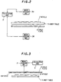
- Fig. 2 shows an apparatus for measuring dimension of an article in the second preferred embodiment according to the invention, wherein like parts are indicated by like reference numerals as used in the first preferred embodiment, provided that the scale plate 4 having the marks for the scale is provided on the opposite side to the article 2.
- the X- and Y- tables are simply shown by a table 1, and the image sensor unit 3 as shown in Fig. 1A is replaced by image sensor units 3A and 3B which are provided at the same positions on the opposite sides relative to the table 1.
- the article 2 and the scale plate 4 are moved to take the same positions relative to the image sensor units 3A and 3B in accordance with the X- and Y- movements of the table 1.
- output signals of the image sensor units 3A and 3B are supplied to the calculation unit 5, in which the output signals are processed to calculate dimension of the article 2.
- Fig. 3 shows an apparatus for measuring dimension of an article in the third preferred embodiment according to the invention, wherein like parts are indicated by like reference numerals as used in the first and second preferred embodiments.
- the scale plate 4 has the scale 4A on the surface facing the article 2 to increase precision in measuring dimension of the article 2 for the reason why both the article 2 and the scale 4A are detected through the scale plate 4 by the image sensor unit 3, so that the influence of a refractive index of the scale plate 4 is commonly applied to the detecting lights of the article 2 and the scale 4A.
- the optical conditions for the image sensor unit 3 of the scale 4A and the article 2 are different to each other. Accordingly, an image of the article 2 is diffracted at the scale plate 4, so that the optical error is occurred by this diffraction.
- Fig. 4 shows an apparatus for measuring dimension of an article in the fourth preferred embodiment according to the invention, wherein like parts are indicated by like reference numerals as used in the first to third preferred embodiments.
- a half mirror 6 is provided at an angle of 45° relative to the X- and Y- table 1 and the scale table 4 having the scale 4A, and shutters 8A and 8B are provided to shut one of light paths for the scale 4A and the article 2.
- the shutters 8A and 8B may be omitted when other means such as using different wavelengths of lights for the scale 4A and the article 2 is adopted.
- a predetermined portion of the article 2 and the relevant marks of the scale 4A are selectively detected in accordance with the switch-over of the shutters 8A and 8B by the image sensor unit 3.
- optical distances can be equal to decrease error.
- Fig. 5 shows an apparatus for measuring the dimension of an article according to a fifth embodiment of the present invention.
- This apparatus comprises: a table 1 having a horizontal surface on which an article to be measured is placed; a marker plate unit 7, disposed parallel to the table 1, comprising a marker plate 4 provided on the side of a reading unit 3 described below and a half mirror 6 provided on the side of the article 2; a reading unit 3, such as a CCD camera, for reading a value corresponding to an arbitrary point on the article 2 and a value, of a marker 4A on the marker plate 4, corresponding to said arbitrary point by taking advantage of light transmitted through and light reflected from the half mirror 6; and a calculation unit 5 for calculating the marker values read by the reading unit 3.
- the marker plate unit 7 is disposed so that the optical distance d 1 , between the article 2 and the half mirror 6 is equal to the optical distance, d 2 , between the marker 4A and the half mirror 6.
- the marker plate 4 has, on its surface, a coordinate marker 4A as shown in Fig. 3 and is formed of a material through which visible light can be passed, for example, glass.
- the marker 4A may also be one representing a dimension, an angle or the like.
- the half mirror 6 comprises a dichroic mirror of which the light reflectance and transmittance vary depending upon the wavelength.
- the reading unit 3 is constructed so as to be movable in X- and Y- directions. A value corresponding to an arbitrary point on the article 2 and a value, of a marker 4A on the marker plate 4, corresponding to said arbitrary point are read by taking advantage of light transmitted through and light reflected form the half mirror 6.
- the reading unit 3 when the reading unit 3 is moved in X- and Y- directions, it reads a arbitrary point of the article 2 on the table 1 by taking advantage of light transmitted through the half mirror 6 and, at the same time, a value, of the marker 4A on the marker plate 4, corresponding to the arbitrary point is read by taking advantage of light reflected from the half mirror 6.
- the reading unit 3 outputs the read marker 4A values into the calculation unit 5 which calculates the input marker 4A values to determine the dimension of the article 2.
- the article 2 and the marker 4A are disposed so that the optical distance between the article 2 and the reading unit 3 is equal to the optical distance between the marker 4A and the reading unit 3. Therefore, even though the reading unit 3 undergoes some change resulting in inclined optical path, the relationship between the article 2 and the reading point of the marker 4A through the half mirror 6 is not broken, enabling the precision of the measurement to be improved.
- the apparatus of the present invention has been described with reference to an embodiment where the reading unit 3 is moved, the apparatus may be constructed so that the table 1 and the marker plate unit 7 are moved instead of the reading unit 3. Further, according to the above embodiment, the marker plate 4 and the half mirror unit 6 are integral with each other to constitute the marker plate unit 7. They, however, may be independent of each other.
- an article to be measured and a marker are disposed so that the optical distance between the article and a reading unit is equal to the optical distance between the marker and the reading unit. This can eliminate the occurrence of parallax, resulting in satisfactory improved precision of the measurement.
Landscapes
- Physics & Mathematics (AREA)
- General Physics & Mathematics (AREA)
- Length Measuring Devices By Optical Means (AREA)
Priority Applications (2)
| Application Number | Priority Date | Filing Date | Title |
|---|---|---|---|
| EP00126219A EP1089052A1 (de) | 1995-11-15 | 1995-11-27 | Apparat und Skala zum Messen einer Dimension eines Gegenstandes |
| EP00126220A EP1091187A1 (de) | 1995-11-15 | 1995-11-27 | Apparat und Skala zum Messen einer Dimension eines Gegenstandes |
Applications Claiming Priority (3)
| Application Number | Priority Date | Filing Date | Title |
|---|---|---|---|
| JP29716395 | 1995-11-15 | ||
| JP07297163A JP3137573B2 (ja) | 1995-11-15 | 1995-11-15 | 計測装置 |
| JP297163/95 | 1995-11-15 |
Related Child Applications (2)
| Application Number | Title | Priority Date | Filing Date |
|---|---|---|---|
| EP00126220A Division EP1091187A1 (de) | 1995-11-15 | 1995-11-27 | Apparat und Skala zum Messen einer Dimension eines Gegenstandes |
| EP00126219A Division EP1089052A1 (de) | 1995-11-15 | 1995-11-27 | Apparat und Skala zum Messen einer Dimension eines Gegenstandes |
Publications (3)
| Publication Number | Publication Date |
|---|---|
| EP0774645A2 true EP0774645A2 (de) | 1997-05-21 |
| EP0774645A3 EP0774645A3 (de) | 1998-05-20 |
| EP0774645B1 EP0774645B1 (de) | 2002-06-12 |
Family
ID=17843010
Family Applications (3)
| Application Number | Title | Priority Date | Filing Date |
|---|---|---|---|
| EP00126220A Withdrawn EP1091187A1 (de) | 1995-11-15 | 1995-11-27 | Apparat und Skala zum Messen einer Dimension eines Gegenstandes |
| EP00126219A Withdrawn EP1089052A1 (de) | 1995-11-15 | 1995-11-27 | Apparat und Skala zum Messen einer Dimension eines Gegenstandes |
| EP95118657A Expired - Lifetime EP0774645B1 (de) | 1995-11-15 | 1995-11-27 | Apparat zum Messen einer Dimension eines Gegenstandes |
Family Applications Before (2)
| Application Number | Title | Priority Date | Filing Date |
|---|---|---|---|
| EP00126220A Withdrawn EP1091187A1 (de) | 1995-11-15 | 1995-11-27 | Apparat und Skala zum Messen einer Dimension eines Gegenstandes |
| EP00126219A Withdrawn EP1089052A1 (de) | 1995-11-15 | 1995-11-27 | Apparat und Skala zum Messen einer Dimension eines Gegenstandes |
Country Status (13)
| Country | Link |
|---|---|
| US (1) | US5644399A (de) |
| EP (3) | EP1091187A1 (de) |
| JP (1) | JP3137573B2 (de) |
| KR (1) | KR100295477B1 (de) |
| CN (1) | CN1069402C (de) |
| AU (1) | AU705435B2 (de) |
| CA (1) | CA2163603A1 (de) |
| DE (1) | DE69527068T2 (de) |
| IL (1) | IL116160A (de) |
| MY (1) | MY112820A (de) |
| PH (1) | PH31360A (de) |
| SG (1) | SG52183A1 (de) |
| TW (1) | TW326492B (de) |
Cited By (1)
| Publication number | Priority date | Publication date | Assignee | Title |
|---|---|---|---|---|
| EP1541961A1 (de) * | 2003-12-13 | 2005-06-15 | Mühlhan Surface Protection International GmbH | Vorrichtung und Verfahren zur Prüfung von Oberflächen, insbesondere von Stahloberflächen, z.B. hinsichtlich Struktur, Farbintensität und/oder Farbverteilung |
Families Citing this family (6)
| Publication number | Priority date | Publication date | Assignee | Title |
|---|---|---|---|---|
| US7034930B1 (en) * | 2000-08-08 | 2006-04-25 | Advanced Micro Devices, Inc. | System and method for defect identification and location using an optical indicia device |
| CN100447525C (zh) * | 2006-09-20 | 2008-12-31 | 上海量具刃具厂 | 影像测量仪的测量方法 |
| CN104034266B (zh) * | 2014-06-16 | 2017-01-25 | 中国科学院长春光学精密机械与物理研究所 | 基于表面微结构的高精度长度检测方法 |
| CN106152947B (zh) | 2015-03-31 | 2019-11-29 | 北京京东尚科信息技术有限公司 | 测量物体尺寸的设备、方法和装置 |
| CN105043269B (zh) * | 2015-07-08 | 2017-09-29 | 上海与德通讯技术有限公司 | 一种物体尺寸的测量方法及电子设备 |
| CN106840108B (zh) * | 2017-01-19 | 2019-01-22 | 东莞中子科学中心 | 视觉测量仪和视觉测量方法 |
Citations (5)
| Publication number | Priority date | Publication date | Assignee | Title |
|---|---|---|---|---|
| DE2939396A1 (de) * | 1978-09-28 | 1980-04-03 | Tokyo Shibaura Electric Co | Lagenabtastvorrichtung |
| DE3323836A1 (de) * | 1983-07-01 | 1985-01-03 | Siemens AG, 1000 Berlin und 8000 München | Verfahren zur festlegung einer koordinate auf einer oberflaeche eines festkoerpers und vorrichtung zur durchfuehrung eines solchen verfahrens |
| WO1990009559A1 (en) * | 1989-02-15 | 1990-08-23 | Josef Zybert | Position determination method and apparatus |
| DE3909855A1 (de) * | 1989-03-25 | 1990-09-27 | Ems Technik Gmbh | Verfahren zur lagerbestimmung einer positionierbaren flaeche sowie lagegeber |
| WO1993006432A1 (en) * | 1991-09-17 | 1993-04-01 | Advanced Robotics (A.R.L.) Ltd. | Precision measuring apparatus |
Family Cites Families (4)
| Publication number | Priority date | Publication date | Assignee | Title |
|---|---|---|---|---|
| US2650518A (en) * | 1951-03-22 | 1953-09-01 | William J Zaroff | Apparatus for measuring feet |
| DE2640284A1 (de) * | 1976-09-08 | 1978-03-09 | Zeiss Carl Fa | Okular zur laengen- und winkelmessung durch ein mikroskop |
| US4393401A (en) * | 1980-11-10 | 1983-07-12 | The Fairchild Engineering Company | Method and apparatus for dimensionally measuring articles |
| JPS6416402A (en) * | 1987-07-10 | 1989-01-19 | Hitachi Ltd | Wheel for adsorbing magnetism |
-
1995
- 1995-11-15 JP JP07297163A patent/JP3137573B2/ja not_active Expired - Lifetime
- 1995-11-23 CA CA002163603A patent/CA2163603A1/en not_active Abandoned
- 1995-11-24 AU AU39050/95A patent/AU705435B2/en not_active Ceased
- 1995-11-27 IL IL11616095A patent/IL116160A/xx not_active IP Right Cessation
- 1995-11-27 EP EP00126220A patent/EP1091187A1/de not_active Withdrawn
- 1995-11-27 US US08/562,733 patent/US5644399A/en not_active Expired - Fee Related
- 1995-11-27 DE DE69527068T patent/DE69527068T2/de not_active Expired - Fee Related
- 1995-11-27 EP EP00126219A patent/EP1089052A1/de not_active Withdrawn
- 1995-11-27 EP EP95118657A patent/EP0774645B1/de not_active Expired - Lifetime
- 1995-11-28 PH PH51794A patent/PH31360A/en unknown
- 1995-11-28 SG SG1995001944A patent/SG52183A1/en unknown
- 1995-11-28 TW TW084112654A patent/TW326492B/zh active
- 1995-11-29 KR KR1019950044838A patent/KR100295477B1/ko not_active IP Right Cessation
- 1995-11-29 CN CN95119638A patent/CN1069402C/zh not_active Expired - Fee Related
- 1995-11-29 MY MYPI95003660A patent/MY112820A/en unknown
Patent Citations (5)
| Publication number | Priority date | Publication date | Assignee | Title |
|---|---|---|---|---|
| DE2939396A1 (de) * | 1978-09-28 | 1980-04-03 | Tokyo Shibaura Electric Co | Lagenabtastvorrichtung |
| DE3323836A1 (de) * | 1983-07-01 | 1985-01-03 | Siemens AG, 1000 Berlin und 8000 München | Verfahren zur festlegung einer koordinate auf einer oberflaeche eines festkoerpers und vorrichtung zur durchfuehrung eines solchen verfahrens |
| WO1990009559A1 (en) * | 1989-02-15 | 1990-08-23 | Josef Zybert | Position determination method and apparatus |
| DE3909855A1 (de) * | 1989-03-25 | 1990-09-27 | Ems Technik Gmbh | Verfahren zur lagerbestimmung einer positionierbaren flaeche sowie lagegeber |
| WO1993006432A1 (en) * | 1991-09-17 | 1993-04-01 | Advanced Robotics (A.R.L.) Ltd. | Precision measuring apparatus |
Cited By (3)
| Publication number | Priority date | Publication date | Assignee | Title |
|---|---|---|---|---|
| EP1541961A1 (de) * | 2003-12-13 | 2005-06-15 | Mühlhan Surface Protection International GmbH | Vorrichtung und Verfahren zur Prüfung von Oberflächen, insbesondere von Stahloberflächen, z.B. hinsichtlich Struktur, Farbintensität und/oder Farbverteilung |
| WO2005057127A1 (de) * | 2003-12-13 | 2005-06-23 | Mühlhan Surface Protection International Gmbh | Vorrichtung und verfahren zur prüfung von oberflächen, insbesondere von stahloberflächen, z. b. hinsichtlich struktur, farbintensität und/oder farbverteilung |
| EP1548401A1 (de) * | 2003-12-13 | 2005-06-29 | Mühlhan Surface Protection International GmbH | Vorrichtung und Verfahren zur Prüfung von Oberflächen, insbesondere von Stahloberflächen, z.B. hinsichtlich Struktur, Farbintensität und/oder Farbverteilung |
Also Published As
| Publication number | Publication date |
|---|---|
| JP3137573B2 (ja) | 2001-02-26 |
| DE69527068T2 (de) | 2002-10-02 |
| EP0774645B1 (de) | 2002-06-12 |
| US5644399A (en) | 1997-07-01 |
| EP1091187A1 (de) | 2001-04-11 |
| AU705435B2 (en) | 1999-05-20 |
| EP1089052A1 (de) | 2001-04-04 |
| IL116160A0 (en) | 1996-01-31 |
| SG52183A1 (en) | 1998-09-28 |
| CA2163603A1 (en) | 1997-05-16 |
| DE69527068D1 (de) | 2002-07-18 |
| JPH09138108A (ja) | 1997-05-27 |
| PH31360A (en) | 1998-07-31 |
| CN1150242A (zh) | 1997-05-21 |
| CN1069402C (zh) | 2001-08-08 |
| KR100295477B1 (ko) | 2002-02-28 |
| IL116160A (en) | 1999-11-30 |
| AU3905095A (en) | 1997-05-22 |
| EP0774645A3 (de) | 1998-05-20 |
| MY112820A (en) | 2001-09-29 |
| TW326492B (en) | 1998-02-11 |
Similar Documents
| Publication | Publication Date | Title |
|---|---|---|
| US5812265A (en) | Apparatus for measuring dimension of article and scale to be used in the same | |
| US5369488A (en) | High precision location measuring device wherein a position detector and an interferometer are fixed to a movable holder | |
| JP5882672B2 (ja) | 光学式位置測定装置 | |
| US4025197A (en) | Novel technique for spot position measurement | |
| EP0302512B1 (de) | Vereinfachte Kalibrierung für eine Entfernungsinformationserwerbungsvorrichtung | |
| JPH0467607B2 (de) | ||
| US5767523A (en) | Multiple detector alignment system for photolithography | |
| EP0774645A2 (de) | Apparat und Skala zum Messen einer Dimension eines Gegenstandes | |
| US4684257A (en) | Measuring instrument | |
| EP0475748B1 (de) | Gerät zum Nachweis fremder Teilchen | |
| EP0019941B1 (de) | Ausrichtsystem für eine verkleinernde Projektionsvorrichtung | |
| US6207759B1 (en) | Composition for a cover of a golf ball | |
| GB2153995A (en) | Coordinate measuring instrument | |
| JP3209886B2 (ja) | 計測装置 | |
| TWI724821B (zh) | 微位移測量裝置 | |
| JPH0627645B2 (ja) | 2次元変位検出装置 | |
| JPH01142401A (ja) | 光学式変位測定装置 | |
| EP0271024A2 (de) | Optisches Fokus-Erkennungssystem | |
| JP2711919B2 (ja) | リニアスケール | |
| JPH08320205A (ja) | 干渉縞の評価装置及びそれを用いた回折干渉光学系の検査方法 | |
| JPH07270121A (ja) | 位置センサ | |
| JP3282745B2 (ja) | 2次元距離計を用いた板幅・蛇行測定装置 | |
| JPS5918405A (ja) | 光学的変位測定装置 | |
| JPH08145621A (ja) | エッジ検出装置 | |
| JPH01272041A (ja) | X−yテーブル |
Legal Events
| Date | Code | Title | Description |
|---|---|---|---|
| PUAI | Public reference made under article 153(3) epc to a published international application that has entered the european phase |
Free format text: ORIGINAL CODE: 0009012 |
|
| AK | Designated contracting states |
Kind code of ref document: A2 Designated state(s): BE CH DE FR GB IT LI NL SE |
|
| PUAL | Search report despatched |
Free format text: ORIGINAL CODE: 0009013 |
|
| AK | Designated contracting states |
Kind code of ref document: A3 Designated state(s): BE CH DE FR GB IT LI NL SE |
|
| 17P | Request for examination filed |
Effective date: 19981120 |
|
| 17Q | First examination report despatched |
Effective date: 20000718 |
|
| GRAG | Despatch of communication of intention to grant |
Free format text: ORIGINAL CODE: EPIDOS AGRA |
|
| RTI1 | Title (correction) |
Free format text: APPARATUS FOR MEASURING DIMENSION OF ARTICLE |
|
| GRAG | Despatch of communication of intention to grant |
Free format text: ORIGINAL CODE: EPIDOS AGRA |
|
| GRAH | Despatch of communication of intention to grant a patent |
Free format text: ORIGINAL CODE: EPIDOS IGRA |
|
| GRAH | Despatch of communication of intention to grant a patent |
Free format text: ORIGINAL CODE: EPIDOS IGRA |
|
| GRAA | (expected) grant |
Free format text: ORIGINAL CODE: 0009210 |
|
| AK | Designated contracting states |
Kind code of ref document: B1 Designated state(s): BE CH DE FR GB IT LI NL SE |
|
| REG | Reference to a national code |
Ref country code: GB Ref legal event code: FG4D |
|
| REG | Reference to a national code |
Ref country code: CH Ref legal event code: EP |
|
| REG | Reference to a national code |
Ref country code: CH Ref legal event code: NV Representative=s name: BUECHEL, KAMINSKI & PARTNER PATENTANWAELTE ESTABLI |
|
| REF | Corresponds to: |
Ref document number: 69527068 Country of ref document: DE Date of ref document: 20020718 |
|
| PGFP | Annual fee paid to national office [announced via postgrant information from national office to epo] |
Ref country code: SE Payment date: 20021106 Year of fee payment: 8 |
|
| ET | Fr: translation filed | ||
| PGFP | Annual fee paid to national office [announced via postgrant information from national office to epo] |
Ref country code: FR Payment date: 20021108 Year of fee payment: 8 |
|
| PGFP | Annual fee paid to national office [announced via postgrant information from national office to epo] |
Ref country code: GB Payment date: 20021127 Year of fee payment: 8 |
|
| PGFP | Annual fee paid to national office [announced via postgrant information from national office to epo] |
Ref country code: DE Payment date: 20021128 Year of fee payment: 8 |
|
| PGFP | Annual fee paid to national office [announced via postgrant information from national office to epo] |
Ref country code: NL Payment date: 20021129 Year of fee payment: 8 Ref country code: CH Payment date: 20021129 Year of fee payment: 8 |
|
| PGFP | Annual fee paid to national office [announced via postgrant information from national office to epo] |
Ref country code: BE Payment date: 20030121 Year of fee payment: 8 |
|
| PLBE | No opposition filed within time limit |
Free format text: ORIGINAL CODE: 0009261 |
|
| STAA | Information on the status of an ep patent application or granted ep patent |
Free format text: STATUS: NO OPPOSITION FILED WITHIN TIME LIMIT |
|
| 26N | No opposition filed |
Effective date: 20030313 |
|
| PG25 | Lapsed in a contracting state [announced via postgrant information from national office to epo] |
Ref country code: GB Free format text: LAPSE BECAUSE OF NON-PAYMENT OF DUE FEES Effective date: 20031127 |
|
| PG25 | Lapsed in a contracting state [announced via postgrant information from national office to epo] |
Ref country code: SE Free format text: LAPSE BECAUSE OF NON-PAYMENT OF DUE FEES Effective date: 20031128 |
|
| PG25 | Lapsed in a contracting state [announced via postgrant information from national office to epo] |
Ref country code: LI Free format text: LAPSE BECAUSE OF NON-PAYMENT OF DUE FEES Effective date: 20031130 Ref country code: CH Free format text: LAPSE BECAUSE OF NON-PAYMENT OF DUE FEES Effective date: 20031130 Ref country code: BE Free format text: LAPSE BECAUSE OF NON-PAYMENT OF DUE FEES Effective date: 20031130 |
|
| BERE | Be: lapsed |
Owner name: *JAPAN EM CO. LTD Effective date: 20031130 |
|
| PG25 | Lapsed in a contracting state [announced via postgrant information from national office to epo] |
Ref country code: NL Free format text: LAPSE BECAUSE OF NON-PAYMENT OF DUE FEES Effective date: 20040601 |
|
| PG25 | Lapsed in a contracting state [announced via postgrant information from national office to epo] |
Ref country code: DE Free format text: LAPSE BECAUSE OF NON-PAYMENT OF DUE FEES Effective date: 20040602 |
|
| EUG | Se: european patent has lapsed | ||
| GBPC | Gb: european patent ceased through non-payment of renewal fee |
Effective date: 20031127 |
|
| REG | Reference to a national code |
Ref country code: CH Ref legal event code: PL |
|
| PG25 | Lapsed in a contracting state [announced via postgrant information from national office to epo] |
Ref country code: FR Free format text: LAPSE BECAUSE OF NON-PAYMENT OF DUE FEES Effective date: 20040730 |
|
| NLV4 | Nl: lapsed or anulled due to non-payment of the annual fee |
Effective date: 20040601 |
|
| REG | Reference to a national code |
Ref country code: FR Ref legal event code: ST |
|
| PG25 | Lapsed in a contracting state [announced via postgrant information from national office to epo] |
Ref country code: IT Free format text: LAPSE BECAUSE OF NON-PAYMENT OF DUE FEES Effective date: 20051127 |