EP0774429A1 - Hochgeschwindigkeits-Förderanlage hoher Kapazität mit vertikal übereinander angeordneten Artikel-tragenden Bändern - Google Patents
Hochgeschwindigkeits-Förderanlage hoher Kapazität mit vertikal übereinander angeordneten Artikel-tragenden Bändern Download PDFInfo
- Publication number
- EP0774429A1 EP0774429A1 EP96850192A EP96850192A EP0774429A1 EP 0774429 A1 EP0774429 A1 EP 0774429A1 EP 96850192 A EP96850192 A EP 96850192A EP 96850192 A EP96850192 A EP 96850192A EP 0774429 A1 EP0774429 A1 EP 0774429A1
- Authority
- EP
- European Patent Office
- Prior art keywords
- dolly
- articles
- collection
- rail
- endless belts
- Prior art date
- Legal status (The legal status is an assumption and is not a legal conclusion. Google has not performed a legal analysis and makes no representation as to the accuracy of the status listed.)
- Withdrawn
Links
Images


Classifications
-
- B—PERFORMING OPERATIONS; TRANSPORTING
- B65—CONVEYING; PACKING; STORING; HANDLING THIN OR FILAMENTARY MATERIAL
- B65G—TRANSPORT OR STORAGE DEVICES, e.g. CONVEYORS FOR LOADING OR TIPPING, SHOP CONVEYOR SYSTEMS OR PNEUMATIC TUBE CONVEYORS
- B65G17/00—Conveyors having an endless traction element, e.g. a chain, transmitting movement to a continuous or substantially-continuous load-carrying surface or to a series of individual load-carriers; Endless-chain conveyors in which the chains form the load-carrying surface
- B65G17/30—Details; Auxiliary devices
- B65G17/32—Individual load-carriers
- B65G17/34—Individual load-carriers having flat surfaces, e.g. platforms, grids, forks
- B65G17/345—Individual load-carriers having flat surfaces, e.g. platforms, grids, forks the surfaces being equipped with a conveyor
-
- B—PERFORMING OPERATIONS; TRANSPORTING
- B65—CONVEYING; PACKING; STORING; HANDLING THIN OR FILAMENTARY MATERIAL
- B65G—TRANSPORT OR STORAGE DEVICES, e.g. CONVEYORS FOR LOADING OR TIPPING, SHOP CONVEYOR SYSTEMS OR PNEUMATIC TUBE CONVEYORS
- B65G47/00—Article or material-handling devices associated with conveyors; Methods employing such devices
- B65G47/74—Feeding, transfer, or discharging devices of particular kinds or types
- B65G47/94—Devices for flexing or tilting travelling structures; Throw-off carriages
- B65G47/96—Devices for tilting links or platform
-
- B—PERFORMING OPERATIONS; TRANSPORTING
- B65—CONVEYING; PACKING; STORING; HANDLING THIN OR FILAMENTARY MATERIAL
- B65G—TRANSPORT OR STORAGE DEVICES, e.g. CONVEYORS FOR LOADING OR TIPPING, SHOP CONVEYOR SYSTEMS OR PNEUMATIC TUBE CONVEYORS
- B65G2201/00—Indexing codes relating to handling devices, e.g. conveyors, characterised by the type of product or load being conveyed or handled
- B65G2201/02—Articles
- B65G2201/0288—Signatures, i.e. sections of printed magazines, papers or books
-
- B—PERFORMING OPERATIONS; TRANSPORTING
- B65—CONVEYING; PACKING; STORING; HANDLING THIN OR FILAMENTARY MATERIAL
- B65G—TRANSPORT OR STORAGE DEVICES, e.g. CONVEYORS FOR LOADING OR TIPPING, SHOP CONVEYOR SYSTEMS OR PNEUMATIC TUBE CONVEYORS
- B65G2207/00—Indexing codes relating to constructional details, configuration and additional features of a handling device, e.g. Conveyors
- B65G2207/18—Crossing conveyors
Definitions
- the invention relates to the high-speed, high-volume conveying of small articles, for example postal envelopes or parcels in mail order selling organizations, where a high number of articles with limited size and weight, such as parcels, books and the like, are to be conveyed rapidly to respective collection stations along the conveying line and then transferred thereto.
- a first such proposal involves a transport device comprised of two machines arranged in parallel, i.e., two carrousels, each comprising a certain number of dollies, with the articles being fed to these machines at their own loading stations.
- This solution allows the productivity of the plant to be markedly increased, but exhibits the drawback that twice as many collection stations are needed, and that the transport device must travel to two loading stations during each trip.
- This proposal is therefore only convenient when the number of destinations is limited, so that it is not too expensive to provide twicc the number of collection stations and then gather the articles after transferring them.
- Another known proposal consists in combining with each transport device two loading stations, the first loading station being arranged at the beginning of the conveying path and the second loading section being arranged half way along the path. A pre-selection of the objects is performed so as to send to the first loading station the objects that are to be discharged along the first half of the conveying path, with the other articles being sent to the second loading station. That proposal allows productivity to be increased, but it exhibits the drawback of the highly expensive need for carrying out a preselection of the articles in order to send them to the proper loading station.
- the present invention proposes a transport dolly having rotary mats that are superimposed one above the other, there preferably being two pairs of such superimposed mats.
- the apparatus has approximately the same dimensions as similar apparatuses having single mats.
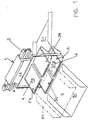
- the apparatus comprises a dolly 1 that moves along a fixed path preferably defined by a rail 2.
- a first pair of vertically superimposed rotary mats i.e., endless rotary belts, 3U, 3L is mounted on the dolly, and a second pair of vertically superimposed rotary mats, i.e., 3'U and 3'L is mounted on the dolly next to the first pair.
- Each of the mats forms a transport surface for an article 4.
- the depicted rail 2 is an elevated rail, with the dolly 1 suspended downwardly therefrom, but instead the rail could be a ground rail with the dolly projecting upwardly therefrom.
- the dolly 1 includes a frame 6 provided with drive wheels 7, having horizontal axes, resting on the upper edge 2A of the rail 2, and also provided with guide wheels or idle wheels 8, having vertical axes, engaging the sides 2B of the rail.
- a motor 9 (Fig. 4) is mounted on the frame 6 and, through a belt 10, rotates a pulley 11 fitted to a drive shaft 11A.
- the drive shaft 11 rotates the drive wheels 7.
- a motor can be mounted on each dolly or it is possible to provide one motor for a plurality of dollies that are linked to one another by means of suitable tie rods 12 or the like (see Fig. 3).
- the frame 6 carries bus bars 13 for making electrical connection with a power source supported by the rail 2 for supplying the necessary power to motor 12 and to the drive motors for the mats and the dollies, and partly for the transmission of data for controlling the operation of the apparatus.
- a structure consisting of a pair of stanchions 14 or the like is fixed, with the rotary mats being mounted on the stanchions.
- the mats of each pair of mats are arranged in vertically superimposed relationship at such heiqhts as to be level with the mouths of respectively vertically superimposed collection devices 5U, 5L (e.g., chutes, containers, conveyor belts) that are arranged at the collection stations along the path of conveyance.
- a framework 15 for the support of the rotary mats is secured, said mats being each provided with a motor 16 that is also operated by power received from the bus bars 13 to rotate the mats by means of belts 17.
- the superimposed mats will provide the possibility of discharging the articles 4 into separate vertically spaced collection devices at each collection station, with the mouths of the collection devices arranged in registry with respective ones of the mats. Alternatively, more than one of the articles can be discharged into the same collection device.
- an apparatus will be provided at the loading station that is able to load articles selectively onto the upper and lower dollies, depending on the collection device into which the articles are to be directed, which apparatus is described in concurrently filed Application Serial No. of Soldavini (Attorney Docket No. 024444-292), the disclosure of which is incorporated by reference herein.
- collection devices that can direct an article toward either of two vertically spaced collection devices.
- Such collection devices could comprise hoppers that are provided with movable chutes, which hoppers are the object of concurrently filed Application Serial No. of Soldavini (Attorney Docket No. 024444-295), the disclosure of which is incorporated by reference herein.
- the present apparatus operates as follows. At the moment of loading, the electronic system charged with handling the overall facility assigns to each article, according to its destination, the first empty mat which arrives at the loading station. Either the upper mat 3U or the lower mat 3L will be selected, depending on the configuration of the particular collection device, and the article will be automatically loaded onto that mat when it becomes in registry with the loading station. It is clear that if the collection station does not have separate collection devices at different levels, but rather has one collection device capable of carrying out a further selection of a conveying route so as to direct an article towards a selected collecting bin, regardless of whether it comes from the upper mat or the lower mat, the machine handling system will assign the article to the first empty mat at either level.
- this invention offers positive advantages because it allows, without changing the size of the facility, an almost double production to be obtained, without needing to increase the running speed of the dollies or use two separate machines.
- Fig. 4 shows a modification similar to that described above, wherein the dolly 1' is mounted on two parallel rails 7, instead of on one rail.
Landscapes
- Engineering & Computer Science (AREA)
- Mechanical Engineering (AREA)
- Discharge Of Articles From Conveyors (AREA)
- Intermediate Stations On Conveyors (AREA)
- Sorting Of Articles (AREA)
Applications Claiming Priority (2)
| Application Number | Priority Date | Filing Date | Title |
|---|---|---|---|
| ITMI952360 | 1995-11-16 | ||
| IT95MI002360A IT1276145B1 (it) | 1995-11-16 | 1995-11-16 | Apparecchiatura smistatrice con celle di trasporto degli oggetti su piani sovrapposti |
Publications (1)
| Publication Number | Publication Date |
|---|---|
| EP0774429A1 true EP0774429A1 (de) | 1997-05-21 |
Family
ID=11372536
Family Applications (1)
| Application Number | Title | Priority Date | Filing Date |
|---|---|---|---|
| EP96850192A Withdrawn EP0774429A1 (de) | 1995-11-16 | 1996-11-13 | Hochgeschwindigkeits-Förderanlage hoher Kapazität mit vertikal übereinander angeordneten Artikel-tragenden Bändern |
Country Status (3)
| Country | Link |
|---|---|
| EP (1) | EP0774429A1 (de) |
| JP (1) | JPH09216721A (de) |
| IT (1) | IT1276145B1 (de) |
Cited By (8)
| Publication number | Priority date | Publication date | Assignee | Title |
|---|---|---|---|---|
| EP0927689A1 (de) * | 1997-12-29 | 1999-07-07 | Sandvik Aktiebolag | Verfahren und Vorrichtung mit hoher Produktivität zum Sortieren von Paketen |
| US6478138B1 (en) | 1999-10-04 | 2002-11-12 | Rapistan Systems Advertising Corp. | Double width crossbelt sorter |
| US6889814B2 (en) | 2001-05-30 | 2005-05-10 | Rapistan Systems Advertising Corp. | Article sortation system |
| US7170024B2 (en) | 1999-08-02 | 2007-01-30 | Siemens Energy & Automation | Delivery point sequencing mail sorting system with flat mail capability |
| US7938252B2 (en) | 2007-12-21 | 2011-05-10 | Cinetic Sorting Corp. | Unstacking conveyor with floating surface |
| DE102013218376A1 (de) * | 2013-09-13 | 2015-03-19 | Siemens Aktiengesellschaft | Querbandsortertransportelement |
| US9145272B2 (en) | 2011-08-16 | 2015-09-29 | Crisplant A/S | Cross-belt sorting system |
| EP2578520B1 (de) * | 2011-10-04 | 2015-12-30 | BEUMER GmbH & Co. KG | Fördervorrichtung |
Citations (6)
| Publication number | Priority date | Publication date | Assignee | Title |
|---|---|---|---|---|
| CH515163A (de) * | 1966-04-14 | 1971-11-15 | Int Standard Electric Corp | Aufzug zum Umschlag von Fördergut zwischen auf verschiedenen Höhen befindlichen Fördereinrichtungen bzw. Förderstrecken |
| GB2111933A (en) | 1981-12-24 | 1983-07-13 | Francesco Canziani | Unloading means for conveying apparatus |
| EP0343612A2 (de) | 1988-05-23 | 1989-11-29 | Francesco Canziani | Verfahren und Vorrichtung für die Entladekontrolle von Gegenständen bei einer automatischen Sortiervorrichtung |
| EP0343613A2 (de) | 1988-05-23 | 1989-11-29 | Francesco Canziani | Verfahren für die Kontrolle der exakten Positionierung von Gegenständen zum Sortieren bei einer automatischen Sortieranlage |
| WO1992011098A1 (en) * | 1990-12-17 | 1992-07-09 | Australian Postal Corporation | Tilt tray sorter accessory |
| EP0611709A2 (de) * | 1993-02-19 | 1994-08-24 | FINMECCANICA S.p.A. | Verteilförderer mit Einrichtungen, die die Transportplatten in horizontaler Stellung halten |
-
1995
- 1995-11-16 IT IT95MI002360A patent/IT1276145B1/it active IP Right Grant
-
1996
- 1996-11-13 EP EP96850192A patent/EP0774429A1/de not_active Withdrawn
- 1996-11-18 JP JP8306549A patent/JPH09216721A/ja active Pending
Patent Citations (6)
| Publication number | Priority date | Publication date | Assignee | Title |
|---|---|---|---|---|
| CH515163A (de) * | 1966-04-14 | 1971-11-15 | Int Standard Electric Corp | Aufzug zum Umschlag von Fördergut zwischen auf verschiedenen Höhen befindlichen Fördereinrichtungen bzw. Förderstrecken |
| GB2111933A (en) | 1981-12-24 | 1983-07-13 | Francesco Canziani | Unloading means for conveying apparatus |
| EP0343612A2 (de) | 1988-05-23 | 1989-11-29 | Francesco Canziani | Verfahren und Vorrichtung für die Entladekontrolle von Gegenständen bei einer automatischen Sortiervorrichtung |
| EP0343613A2 (de) | 1988-05-23 | 1989-11-29 | Francesco Canziani | Verfahren für die Kontrolle der exakten Positionierung von Gegenständen zum Sortieren bei einer automatischen Sortieranlage |
| WO1992011098A1 (en) * | 1990-12-17 | 1992-07-09 | Australian Postal Corporation | Tilt tray sorter accessory |
| EP0611709A2 (de) * | 1993-02-19 | 1994-08-24 | FINMECCANICA S.p.A. | Verteilförderer mit Einrichtungen, die die Transportplatten in horizontaler Stellung halten |
Cited By (15)
| Publication number | Priority date | Publication date | Assignee | Title |
|---|---|---|---|---|
| EP0927689A1 (de) * | 1997-12-29 | 1999-07-07 | Sandvik Aktiebolag | Verfahren und Vorrichtung mit hoher Produktivität zum Sortieren von Paketen |
| US7982156B2 (en) | 1999-08-02 | 2011-07-19 | Siemens Industry, Inc. | Delivery point sequencing mail sorting system with flat mail capability |
| US7170024B2 (en) | 1999-08-02 | 2007-01-30 | Siemens Energy & Automation | Delivery point sequencing mail sorting system with flat mail capability |
| US7589294B2 (en) | 1999-08-02 | 2009-09-15 | Siemens Energy & Automation, Inc. | Delivery point sequencing mail sorting system with flat mail capability |
| US6478138B1 (en) | 1999-10-04 | 2002-11-12 | Rapistan Systems Advertising Corp. | Double width crossbelt sorter |
| US6585101B2 (en) | 1999-10-04 | 2003-07-01 | Rapisten Systems Advertising Corp. | Double width sorter |
| US6889814B2 (en) | 2001-05-30 | 2005-05-10 | Rapistan Systems Advertising Corp. | Article sortation system |
| US7145095B2 (en) | 2001-05-30 | 2006-12-05 | Dematic Corp. | Article sortation system |
| US7863536B2 (en) | 2001-05-30 | 2011-01-04 | Dematic S.R.L. | Article sortation system |
| US7938252B2 (en) | 2007-12-21 | 2011-05-10 | Cinetic Sorting Corp. | Unstacking conveyor with floating surface |
| US9145272B2 (en) | 2011-08-16 | 2015-09-29 | Crisplant A/S | Cross-belt sorting system |
| EP2578520B1 (de) * | 2011-10-04 | 2015-12-30 | BEUMER GmbH & Co. KG | Fördervorrichtung |
| US9796538B2 (en) | 2011-10-04 | 2017-10-24 | Beumer Gmbh & Co. Kg | Conveyor apparatus |
| DE102013218376A1 (de) * | 2013-09-13 | 2015-03-19 | Siemens Aktiengesellschaft | Querbandsortertransportelement |
| DE102013218376B4 (de) * | 2013-09-13 | 2016-10-27 | Siemens Aktiengesellschaft | Querbandsortertransportelement |
Also Published As
| Publication number | Publication date |
|---|---|
| ITMI952360A1 (it) | 1997-05-16 |
| IT1276145B1 (it) | 1997-10-27 |
| ITMI952360A0 (de) | 1995-11-16 |
| JPH09216721A (ja) | 1997-08-19 |
Similar Documents
| Publication | Publication Date | Title |
|---|---|---|
| EP0774431A1 (de) | Verfahren und Vorrichtung zum Laden von Artikeln auf vertikal beabstandeten Ladeflächen von einer bewegten Transporteinrichtung | |
| EP1242197B1 (de) | Automatisches behälterbehandlungssystem für einen sortierer | |
| EP1970131B1 (de) | System zum Sortieren und zur Reihenfolgeplanung von Postsendungen | |
| EP1220719B1 (de) | Querbandsortiersystem | |
| EP2769776B1 (de) | Sortiervorrichtung mit kippbarem Trägerelement | |
| US8113334B2 (en) | Matrix sorter system | |
| US10022752B1 (en) | Package sorting module, system, and method of using the same | |
| CN1671488A (zh) | 单程排序组件 | |
| GB2111933A (en) | Unloading means for conveying apparatus | |
| US20080257798A1 (en) | Method and Device for Sorting Postal Items | |
| EP0952101A2 (de) | Verfahren und Vorrichtung zur Hochgeschwindigkeitsbehandlung von Gegenständen | |
| EP0774429A1 (de) | Hochgeschwindigkeits-Förderanlage hoher Kapazität mit vertikal übereinander angeordneten Artikel-tragenden Bändern | |
| KR20010034284A (ko) | 분류된 우편물 컨테이너용 배급 시스템 및 그 방법 | |
| US3193080A (en) | Multiple station feeding means | |
| US5937994A (en) | Container conveying installation for preparing sets of objects | |
| CN111976012A (zh) | 混凝土搅拌站上料系统 | |
| CN112371521B (zh) | 一种快递运转设备 | |
| JP2509954B2 (ja) | 高速自動仕分装置の荷物移載方法 | |
| CN112371533B (zh) | 一种快递智能化分拣系统 | |
| JPH0289795A (ja) | 異質物振分け処理装置 | |
| JP2000079945A (ja) | 農産物の選別包装装置 | |
| JPH10218352A (ja) | 物品の仕分け装置およびその仕分け方法 | |
| CN114345715A (zh) | 一种用于电商物流的包裹分拣机 | |
| JPH07308640A (ja) | 回収びん等の整列及び形状選別装置 | |
| JPS63171230A (ja) | プレス成形部品の搬送装置 |
Legal Events
| Date | Code | Title | Description |
|---|---|---|---|
| PUAI | Public reference made under article 153(3) epc to a published international application that has entered the european phase |
Free format text: ORIGINAL CODE: 0009012 |
|
| AK | Designated contracting states |
Kind code of ref document: A1 Designated state(s): AT BE CH DE DK ES FR GB IE IT LI LU NL PT SE |
|
| 17P | Request for examination filed |
Effective date: 19980131 |
|
| 17Q | First examination report despatched |
Effective date: 20000316 |
|
| STAA | Information on the status of an ep patent application or granted ep patent |
Free format text: STATUS: THE APPLICATION IS DEEMED TO BE WITHDRAWN |
|
| 18D | Application deemed to be withdrawn |
Effective date: 20000727 |