EP0774381A2 - Roof rails for vehicles - Google Patents
Roof rails for vehicles Download PDFInfo
- Publication number
- EP0774381A2 EP0774381A2 EP96113720A EP96113720A EP0774381A2 EP 0774381 A2 EP0774381 A2 EP 0774381A2 EP 96113720 A EP96113720 A EP 96113720A EP 96113720 A EP96113720 A EP 96113720A EP 0774381 A2 EP0774381 A2 EP 0774381A2
- Authority
- EP
- European Patent Office
- Prior art keywords
- railing
- tube
- roof
- support
- plug
- Prior art date
- Legal status (The legal status is an assumption and is not a legal conclusion. Google has not performed a legal analysis and makes no representation as to the accuracy of the status listed.)
- Withdrawn
Links
Images


Classifications
-
- B—PERFORMING OPERATIONS; TRANSPORTING
- B60—VEHICLES IN GENERAL
- B60R—VEHICLES, VEHICLE FITTINGS, OR VEHICLE PARTS, NOT OTHERWISE PROVIDED FOR
- B60R9/00—Supplementary fittings on vehicle exterior for carrying loads, e.g. luggage, sports gear or the like
- B60R9/04—Carriers associated with vehicle roof
Definitions
- the invention relates to a roof rail for vehicles, consisting of a railing pipe and a support foot at each railing pipe end.
- DE 42 41 771 A1 has disclosed a plug connection with a plug pin that has at least one convex-shaped front end and a disk attached centrally as the plug connection securing means, whereby the disc, which in the starting position has a larger diameter than the plug, can adapt when inserting the plug into the receiving bore, its diameter and the convex shape of the plug end face, and the disc is designed with a plurality of radial, free-running slots.
- a roof railing in which a plastic grommet which is pushed onto the plug-in pin of a support foot and engages radially by means of a locking lug in a wall opening of the railing tube.
- the plastic grommet also has an inner ring bead for snapping into an annular groove of the plug-in pin.
- plug connections are known from the prior art (cf. US 52 55 993 and US 44 49 656), in which a locking cam is loaded by a spring means or is formed as an integral part of the spring means.
- the invention is based on a roof railing of the type mentioned the task to achieve a further simplification of the plug connection between a railing pipe and a support foot or the means securing the plug connection while ensuring that the technical requirements fully sufficient safety against withdrawal.
- a reduction in cost, simplification, ease of assembly and a weight saving of the entire roof rails are sought.
- a roof rail for vehicles consisting of a railing tube and a support leg at each railing tube end with a hollow support leg lower part open at the top, a support plate formed on the support leg lower part, at least one bore penetrating the support plate for at least one fastening element, proposed on the lower part of the support leg, inserted into a railing pipe, an axially aligned space between the spigot and the railing pipe, a free space arranged, the spigot bracing the railing pipe and a cover cap proposed as a supporting foot upper part.
- the individual elements of the combination of features according to the invention are quite suitable for promoting and supporting one another.
- the two-part design of the support foot with the support foot lower part assuming the carrying function and the support foot upper part which takes on more of a covering and decorative function and is designed as a cover cap simplifies production and ensures material and weight savings.
- the support plate and fastener are freely accessible, which simplifies assembly.
- the free space between the spigot and the railing tube, which is completely or partially filled by the mounting element makes compliance with narrow tolerances superfluous, which in turn benefits the ease of manufacture.
- the plug-in pin is designed with a latching cam which engages in an opening in the railing tube for the purpose of additional positive locking on the railing tube. In this way, a particularly reliable non-positive and positive connection between the support foot and the railing tube is guaranteed.
- the holding element preferably consists of a wedge which can be driven into the free space.
- a wedge is a simple, inexpensive to manufacture and assemble component and works by self-locking.
- An expedient embodiment of the invention provides that the wedge has an extension tongue which projects into the cavity of the lower part of the support foot and has a through hole for anchoring a clip element of the cover cap.
- the wedge thus fulfills on the one hand the function of a non-positive connection element for fixing the lower part of the support leg on the railing tube and on the other hand the function of a holding element for the upper part of the support leg designed as a cover cap.
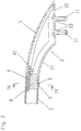
- Fig. 1 two roof rails, which extend along the lateral roof edges, are attached to a vehicle roof 1.
- Each roof rail consists of a railing tube 3 and a support leg 2 at the railing tube ends.
- Cross bars 10 indicated by dash-dotted lines can be attached to the railing tubes 3.
- the support foot 2 is formed from a support foot lower part 21 and a support foot upper part designed as a cover cap 5.
- the lower leg 21 is hollow and open at the top and closable by the cap 5.
- the lower part 21 of the supporting foot has a support plate 22 with bores 23 at the lower end for carrying out fastening elements 11 which serve to fasten the roof rails.
- the lower support leg 21 carries a plug pin 8 which engages in an end region of the railing tube 3.
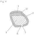
- the cross-sectional area of the plug pin 8 is smaller than the opening cross-section of the railing tube 3 due to a flattening in order to form a free space 12 for receiving a mounting element.
- the holding element consists of a wedge 4 which can be driven into the free space 12 and by means of which the plug-in pin 8 is braced with the railing tube 3.
- a positive connection is additionally provided, which is formed by a locking cam 7 located on the plug pin 8, which engages in a bore 6 of the railing tube 3.
- the wedge 4 is provided with an extension tongue 41 protruding into the cavity of the lower part 21 of the supporting foot and having a through opening 9.
- the through opening 9 is used to fix the covering cap 5 by one clip pins 51 formed thereon.
Abstract
Description
Die Erfindung bezieht sieh auf eine Dachreling für Fahrzeuge, bestehend aus einem Relingrohr und einem Stützfuß an jedem Relingrohrende.The invention relates to a roof rail for vehicles, consisting of a railing pipe and a support foot at each railing pipe end.
Gegenüber den herkömmlichen die Steckverbindungen sichernden Mitteln, wie Schrauben, Nieten, Stiften oder Verkleben ist durch die DE 42 41 771 A1 eine Steckverbindung mit einem Steckzapfen bekanntgeworden, der zumindest ein konvexgeformtes Stirnende und eine zentrisch daran befestigte Scheibe als die Steckverbindung sicherndes Mittel aufweist, wobei die Scheibe, die in der Ausgangslage einen gegenüber dem Steckzapfen größeren Durchmesser besitzt, sich beim Einstecken des Steckzapfens in die Aufnahmebohrung, deren Durchmesser und der konvexen Form des Steckzapfenstirnendes anzupassen vermag und wobei die Scheibe mit mehreren radialen, nach außen freiauslaufenden Schlitzen ausgebildet ist.Compared to the conventional means securing the plug connections, such as screws, rivets, pins or gluing, DE 42 41 771 A1 has disclosed a plug connection with a plug pin that has at least one convex-shaped front end and a disk attached centrally as the plug connection securing means, whereby the disc, which in the starting position has a larger diameter than the plug, can adapt when inserting the plug into the receiving bore, its diameter and the convex shape of the plug end face, and the disc is designed with a plurality of radial, free-running slots.
Aus der DE 42 30 110 A1 ist ferner eine Dachreling bekannt, bei der eine auf den Steckzapfen eines Stützfußes aufgeschobene und verrastete Kunststofftülle mittels einer Rastnase in eine Wandöffnung des Relingrohrs radial eingreift. Die Kunststofftülle weist zudem einen Innenringwulst zum Einrasten in eine Ringnut des Steckzapfens auf.From DE 42 30 110 A1 a roof railing is also known, in which a plastic grommet which is pushed onto the plug-in pin of a support foot and engages radially by means of a locking lug in a wall opening of the railing tube. The plastic grommet also has an inner ring bead for snapping into an annular groove of the plug-in pin.
Ferner sind aus dem Stand der Technik (vgl. US 52 55 993 und US 44 49 656) Steckverbindungen bekannt, bei denen ein Rastnocken durch ein Federmittel belastet oder als integraler Bestandteil des Federmittels ausgebildet ist.Furthermore, plug connections are known from the prior art (cf. US 52 55 993 and US 44 49 656), in which a locking cam is loaded by a spring means or is formed as an integral part of the spring means.
Der Erfindung liegt ausgehend von einer Dachreling der eingangs genannt Art die Aufgabe zugrunde, eine weitergehende Vereinfachung der Steckverbindung zwischen einem Relingrohr und einem Stützfuß bzw. der die Steckverbindung sichernden Mittel bei Gewährleistung einer den technischen Anforderungen vollauf genügenden Abzugssicherheit zu erzielen. Darüber hinaus wird eine Verbilligung, Vereinfachung, Montageerleichterung und eine Gewichtseinsparung der gesamten Dachreling angestrebt.The invention is based on a roof railing of the type mentioned the task to achieve a further simplification of the plug connection between a railing pipe and a support foot or the means securing the plug connection while ensuring that the technical requirements fully sufficient safety against withdrawal. In addition, a reduction in cost, simplification, ease of assembly and a weight saving of the entire roof rails are sought.
Zur Lösung dieser Aufgabe wird erfindungsgemäß eine Dachreling für Fahrzeuge, bestehend aus einem Relingrohr und einem Stützfuß an jedem Relingrohrende mit einem hohlen nach oben offenen Stützfuß-Unterteil, einer am Stützfuß-Unterteil ausgebildeten Auflagerplatte, zumindest einer die Auflagerplatte durchsetzenden Bohrung für zumindest ein Befestigungselement, einem am Stützfuß-Unterteil ausgebildeten, in ein Relingrohr eingesetzten Steckzapfen, einem axial ausgerichteten Freiraum zwischen Steckzapfen und Relingrohr, einem im Freiraum angeordneten, den Steckzapfen mit dem Relingrohr verspannenden Halterungselement und einer Abdeckkappe als Stützfuß-Oberteil vorgeschlagen.To achieve this object, according to the invention a roof rail for vehicles, consisting of a railing tube and a support leg at each railing tube end with a hollow support leg lower part open at the top, a support plate formed on the support leg lower part, at least one bore penetrating the support plate for at least one fastening element, proposed on the lower part of the support leg, inserted into a railing pipe, an axially aligned space between the spigot and the railing pipe, a free space arranged, the spigot bracing the railing pipe and a cover cap proposed as a supporting foot upper part.
Die Einzelelemente der erfindungsgemäßen Merkmalskombination sind durchaus geeignet, sich gegenseitig zu fördern und zu stützen. Die zweiteilige Ausbildung des Stützfußes mit dem die Tragefunktion übernehmenden Stützfuß-Unterteil und dem mehr eine Abdeck- und Zierfunktion übernehmenden, als Abdeckkappe ausgebildeten Stützfuß-Oberteil erleichtert die Herstellung und sichert eine Material- und Gewichtseinsparung. Die Auflagerplatte nebst Befestigungselement ist frei zugänglich, was die Montage vereinfacht. Gleiches gilt für den Freiraum zwischen Steckzapfen und Relingrohr und insbesondere auch für das Einbringen des den Steckzapfen mit dem Relingrohr verspannenden Halterungselements. Der Freiraum zwischen Steckzapfen und Relingrohr, der durch das Halterungselement ganz oder teilweise ausgefüllt wird, macht die Einhaltung enger Toleranzen überflüssig, was wiederum der einfachen Herstellung zugute kommt.The individual elements of the combination of features according to the invention are quite suitable for promoting and supporting one another. The two-part design of the support foot with the support foot lower part assuming the carrying function and the support foot upper part which takes on more of a covering and decorative function and is designed as a cover cap simplifies production and ensures material and weight savings. The support plate and fastener are freely accessible, which simplifies assembly. The same applies to the free space between the plug pin and the railing tube and in particular also for the introduction of the holding element which braces the plug pin with the railing tube. The free space between the spigot and the railing tube, which is completely or partially filled by the mounting element, makes compliance with narrow tolerances superfluous, which in turn benefits the ease of manufacture.
Gemäß einer Weiterbildung der Erfindung kann vorgesehen sein, daß der Steckzapfen zwecks zusätzlicher formschlüssiger Festlegung am Relingrohr mit einem in eine Öffnung im Relingrohr eingreifenden Rastnocken ausgebildet ist. Auf diese Weise wird eine besonders zuverlässige kraft- und formschlüssig wirkende Verbindung zwischen dem Stützfuß und dem Relingrohr gewährleistet.According to a further development of the invention, it can be provided that the plug-in pin is designed with a latching cam which engages in an opening in the railing tube for the purpose of additional positive locking on the railing tube. In this way, a particularly reliable non-positive and positive connection between the support foot and the railing tube is guaranteed.
Bevorzugterweise besteht das Halterungselement aus einem in den Freiraum eintreibbaren Keil. Ein Keil ist ein einfaches, kostengünstig zu fertigendes und zu montierendes Bauelement und wirkt durch Selbsthemmung.The holding element preferably consists of a wedge which can be driven into the free space. A wedge is a simple, inexpensive to manufacture and assemble component and works by self-locking.
Eine zweckmäßige Ausgestaltung der Erfindung sieht vor, daß der Keil eine in den Hohlraum des Stützfuß-Unterteils hineinragende Verlängerungszunge mit einer Druchgangsbohrung zur Verankerung eines Klipselements der Abdeckkappe aufweist. Damit erfüllt der Keil zum einen die Funktion eines kraftschlüssig wirkenden Verbindungselements für die Festlegung des Stützfuß-Unterteils am Relingrohr und zum anderen die Funktion eines Halterungselements für das als Abdeckkappe ausgebildete Stützfuß-Oberteil.An expedient embodiment of the invention provides that the wedge has an extension tongue which projects into the cavity of the lower part of the support foot and has a through hole for anchoring a clip element of the cover cap. The wedge thus fulfills on the one hand the function of a non-positive connection element for fixing the lower part of the support leg on the railing tube and on the other hand the function of a holding element for the upper part of the support leg designed as a cover cap.
Ein Ausführungsbeispiel der Erfindung wird im folgenden anhand der Zeichnungen näher erläutert, und es zeigen:
- Fig. 1
- ein Fahrzeugdach mit darauf angeordneten Dachrelings,
- Fig. 2
- den Verbindungsbereich zwischen einem Relingrohr und einem Stützfuß im vertikalen Längsschnitt,
- Fig. 3
- den Verbindungsbereich nach Fig. 2 im vergrößerten Maßstab und
- Fig. 4
- einen Schnitt IV - IV nach Fig. 2.
- Fig. 1
- a vehicle roof with roof rails arranged on it,
- Fig. 2
- the connection area between a railing pipe and a support foot in vertical longitudinal section,
- Fig. 3
- 2 on an enlarged scale and
- Fig. 4
- a section IV - IV of FIG. 2nd
In Fig. 1 sind auf einem Fahrzeugdach 1 zwei Dachrelings, die sich entlang der seitlichen Dachränder erstrecken, befestigt. Jede Dachreling besteht aus einem Relingrohr 3 und je einem Stützfuß 2 an den Relingrohrenden. An den Relingrohren 3 sind strichpunktiert angedeutete Querträger 10 befestigbar.In Fig. 1, two roof rails, which extend along the lateral roof edges, are attached to a
Der Stützfuß 2 wird gebildet aus einem Stützfuß-Unterteil 21 und einem als Abdeckkappe 5 ausgebildeten Stützfuß-Oberteil. Das Stützfuß-Unterteil 21 ist hohl und nach oben offen ausgebildet und durch die Abdeckkappe 5 verschließbar. Das Stützfuß-Unterteil 21 weist am unteren Ende eine Auflagerplatte 22 mit Bohrungen 23 zum Durchführen von zur Dachbefestigung der Dachreling dienenden Befestigungselementen 11 auf. Am oberen Ende trägt das Stützfuß-Unterteil 21 einen Steckzapfen 8, der in einen Endbereich des Relingrohrs 3 eingreift. Die Querschnittsfläche des Steckzapfens 8 ist durch eine Abflachung kleiner als der Öffnungsquerschnitt des Relingrohrs 3 zwecks Bildung eines Freiraums 12 zur Aufnahme eines Halterungselements. Das Halterungselement besteht aus einem in den Freiraum 12 eintreibbaren Keil 4, mittels dem der Steckzapfen 8 mit dem Relingrohr 3 verspannt wird.The
Eine formschlüssige Verbindung ist zusätzlich vorgesehen, die gebildet wird durch einen am Steckzapfen 8 befindlichen Rastnocken 7, der in eine Bohrung 6 des Relingrohrs 3 eingreift.A positive connection is additionally provided, which is formed by a
Zur Festlegung des Stützfuß-Oberteils bzw. der Abdeckkappe 5 am Stützfuß-Unterteil 21 ist der Keil 4 mit einer in den Hohlraum des Stützfuß-Unterteils 21 hineinragenden Verlängerungszunge 41 versehen mit einer Durchgangsöffnung 9. Die Durchgangsöffnung 9 wird zur Festlegung der Abdeckkappe 5 von einem daran angeformten Klipszapfen 51 durchsetzt.To fix the upper part of the supporting foot or the
Claims (4)
Applications Claiming Priority (2)
| Application Number | Priority Date | Filing Date | Title |
|---|---|---|---|
| DE19542341 | 1995-11-14 | ||
| DE1995142341 DE19542341A1 (en) | 1995-11-14 | 1995-11-14 | Roof rails for vehicles |
Publications (2)
| Publication Number | Publication Date |
|---|---|
| EP0774381A2 true EP0774381A2 (en) | 1997-05-21 |
| EP0774381A3 EP0774381A3 (en) | 1998-09-16 |
Family
ID=7777381
Family Applications (1)
| Application Number | Title | Priority Date | Filing Date |
|---|---|---|---|
| EP96113720A Withdrawn EP0774381A3 (en) | 1995-11-14 | 1996-08-28 | Roof rails for vehicles |
Country Status (2)
| Country | Link |
|---|---|
| EP (1) | EP0774381A3 (en) |
| DE (1) | DE19542341A1 (en) |
Cited By (2)
| Publication number | Priority date | Publication date | Assignee | Title |
|---|---|---|---|---|
| EP1055559A2 (en) | 1999-05-28 | 2000-11-29 | JAC Products Deutschland GmbH | Method for securing two members together and assembly of members so secured |
| WO2003051674A1 (en) * | 2001-12-15 | 2003-06-26 | Thule Automotive Limited | Roof rail |
Families Citing this family (1)
| Publication number | Priority date | Publication date | Assignee | Title |
|---|---|---|---|---|
| DE102007005653A1 (en) * | 2007-01-31 | 2008-08-07 | Jac Products Deutschland Gmbh | Roof rail for vehicles |
Citations (4)
| Publication number | Priority date | Publication date | Assignee | Title |
|---|---|---|---|---|
| US4279368A (en) * | 1979-03-09 | 1981-07-21 | Four Star Corporation | Stanchion assembly |
| US4616772A (en) * | 1983-01-31 | 1986-10-14 | Mareydt Ray G | Carrier rack and stanchion |
| DE4018178A1 (en) * | 1989-06-07 | 1990-12-13 | Huron St Clair Inc | CARRIER FOR LUGGAGE RACK |
| DE4427776C1 (en) * | 1994-08-05 | 1995-10-05 | Happich Fahrzeug Dachsysteme | Roof rail for vehicle |
Family Cites Families (3)
| Publication number | Priority date | Publication date | Assignee | Title |
|---|---|---|---|---|
| SE436633B (en) * | 1982-04-21 | 1985-01-14 | Thule Ind Ab | LOAD SHARE FOR VEHICLES |
| DE4230110C2 (en) * | 1992-09-09 | 1995-07-06 | Happich Fahrzeug Dachsysteme | Roof rails for motor vehicles |
| DE4241771A1 (en) * | 1992-12-11 | 1994-06-16 | Happich Gmbh Gebr | Roof rails for motor vehicles |
-
1995
- 1995-11-14 DE DE1995142341 patent/DE19542341A1/en not_active Withdrawn
-
1996
- 1996-08-28 EP EP96113720A patent/EP0774381A3/en not_active Withdrawn
Patent Citations (4)
| Publication number | Priority date | Publication date | Assignee | Title |
|---|---|---|---|---|
| US4279368A (en) * | 1979-03-09 | 1981-07-21 | Four Star Corporation | Stanchion assembly |
| US4616772A (en) * | 1983-01-31 | 1986-10-14 | Mareydt Ray G | Carrier rack and stanchion |
| DE4018178A1 (en) * | 1989-06-07 | 1990-12-13 | Huron St Clair Inc | CARRIER FOR LUGGAGE RACK |
| DE4427776C1 (en) * | 1994-08-05 | 1995-10-05 | Happich Fahrzeug Dachsysteme | Roof rail for vehicle |
Cited By (2)
| Publication number | Priority date | Publication date | Assignee | Title |
|---|---|---|---|---|
| EP1055559A2 (en) | 1999-05-28 | 2000-11-29 | JAC Products Deutschland GmbH | Method for securing two members together and assembly of members so secured |
| WO2003051674A1 (en) * | 2001-12-15 | 2003-06-26 | Thule Automotive Limited | Roof rail |
Also Published As
| Publication number | Publication date |
|---|---|
| DE19542341A1 (en) | 1997-05-15 |
| EP0774381A3 (en) | 1998-09-16 |
Similar Documents
| Publication | Publication Date | Title |
|---|---|---|
| AT404219B (en) | DRAWER | |
| EP1794031B1 (en) | Roof rack system for a vehicle, method for producing the roof rack system and vehicle comprising a roof rack system | |
| DE19915119A1 (en) | Mounting element for furniture construction | |
| EP3742932B1 (en) | Front panel for a drawer | |
| DE19958745C1 (en) | Fastening device with spring lock for a seat belt fitting | |
| DE102005037020A1 (en) | Household appliance door, has door carrier unit merged to mounting unit, where carrier unit includes beading units that are connected to hinge by plug and socket connection and fastening unit for form-fit connection with door front unit | |
| EP0580023B1 (en) | Roof rails for vehicles | |
| DE19939615B4 (en) | Seat frame for a seat in motor vehicles | |
| DE202005010186U1 (en) | Bearing device for bearing element to put in C-shaped profile rail has fastening nut and bearing part with hole on its bearing flank holding neck part which has hole to take nut and spacer between neck part and flank | |
| DE3902399A1 (en) | TRIM MOLDINGS | |
| DE4230110C2 (en) | Roof rails for motor vehicles | |
| DE4447121A1 (en) | Releasable lock for cover of ground utility | |
| EP1393993B1 (en) | Airbag Module | |
| EP0774381A2 (en) | Roof rails for vehicles | |
| EP0837254A1 (en) | Hollow wall anchor | |
| EP1099865B1 (en) | Trim fastening especially for motor vehicles | |
| DE4333479A1 (en) | Fastener for coat hook in motor vehicle - consists of clip-like holder to lock into opening in body wall | |
| EP1366942B1 (en) | Fixation for canvas top for convertible vehicle | |
| DE102009057177A1 (en) | Fastening arrangement for profile part at carrier part, particularly for profile part of lateral bumper cover of motor vehicle at body-sided carrier part, has fastening element, with which profile part is fixed at carrier part | |
| DE4427776C1 (en) | Roof rail for vehicle | |
| EP1544029A2 (en) | Footrest for mounting to a vehicle floor | |
| EP1036707A2 (en) | Roof rail for vehicles | |
| EP0717951B1 (en) | Support arm and supporting device with four disposed supporting arms | |
| DE19730279B4 (en) | Device for mounting a seat of a vehicle | |
| DE3317020C1 (en) | Attachment element, which consists of plastic, is constructed as an elongated body having an essentially round cross-section, and has clip connections at the ends |
Legal Events
| Date | Code | Title | Description |
|---|---|---|---|
| PUAI | Public reference made under article 153(3) epc to a published international application that has entered the european phase |
Free format text: ORIGINAL CODE: 0009012 |
|
| 17P | Request for examination filed |
Effective date: 19960911 |
|
| AK | Designated contracting states |
Kind code of ref document: A2 Designated state(s): DE FR GB SE |
|
| PUAL | Search report despatched |
Free format text: ORIGINAL CODE: 0009013 |
|
| AK | Designated contracting states |
Kind code of ref document: A3 Designated state(s): DE FR GB SE |
|
| RAP1 | Party data changed (applicant data changed or rights of an application transferred) |
Owner name: JAC PRODUCTS DEUTSCHLAND GMBH |
|
| GRAG | Despatch of communication of intention to grant |
Free format text: ORIGINAL CODE: EPIDOS AGRA |
|
| 17Q | First examination report despatched |
Effective date: 20001127 |
|
| STAA | Information on the status of an ep patent application or granted ep patent |
Free format text: STATUS: THE APPLICATION HAS BEEN WITHDRAWN |
|
| 18W | Application withdrawn |
Withdrawal date: 20010410 |