EP0774333A2 - Tyre vulcanizing mould provided with venting means - Google Patents
Tyre vulcanizing mould provided with venting means Download PDFInfo
- Publication number
- EP0774333A2 EP0774333A2 EP96118423A EP96118423A EP0774333A2 EP 0774333 A2 EP0774333 A2 EP 0774333A2 EP 96118423 A EP96118423 A EP 96118423A EP 96118423 A EP96118423 A EP 96118423A EP 0774333 A2 EP0774333 A2 EP 0774333A2
- Authority
- EP
- European Patent Office
- Prior art keywords
- valve
- cavern
- collar
- housing
- facing away
- Prior art date
- Legal status (The legal status is an assumption and is not a legal conclusion. Google has not performed a legal analysis and makes no representation as to the accuracy of the status listed.)
- Granted
Links
Images


Classifications
-
- B—PERFORMING OPERATIONS; TRANSPORTING
- B29—WORKING OF PLASTICS; WORKING OF SUBSTANCES IN A PLASTIC STATE IN GENERAL
- B29C—SHAPING OR JOINING OF PLASTICS; SHAPING OF MATERIAL IN A PLASTIC STATE, NOT OTHERWISE PROVIDED FOR; AFTER-TREATMENT OF THE SHAPED PRODUCTS, e.g. REPAIRING
- B29C33/00—Moulds or cores; Details thereof or accessories therefor
- B29C33/10—Moulds or cores; Details thereof or accessories therefor with incorporated venting means
-
- B—PERFORMING OPERATIONS; TRANSPORTING
- B29—WORKING OF PLASTICS; WORKING OF SUBSTANCES IN A PLASTIC STATE IN GENERAL
- B29D—PRODUCING PARTICULAR ARTICLES FROM PLASTICS OR FROM SUBSTANCES IN A PLASTIC STATE
- B29D30/00—Producing pneumatic or solid tyres or parts thereof
- B29D30/02—Solid tyres ; Moulds therefor
-
- B—PERFORMING OPERATIONS; TRANSPORTING
- B29—WORKING OF PLASTICS; WORKING OF SUBSTANCES IN A PLASTIC STATE IN GENERAL
- B29D—PRODUCING PARTICULAR ARTICLES FROM PLASTICS OR FROM SUBSTANCES IN A PLASTIC STATE
- B29D30/00—Producing pneumatic or solid tyres or parts thereof
- B29D30/06—Pneumatic tyres or parts thereof (e.g. produced by casting, moulding, compression moulding, injection moulding, centrifugal casting)
- B29D30/0601—Vulcanising tyres; Vulcanising presses for tyres
- B29D30/0606—Vulcanising moulds not integral with vulcanising presses
- B29D2030/0607—Constructional features of the moulds
- B29D2030/0617—Venting devices, e.g. vent plugs or inserts
-
- B—PERFORMING OPERATIONS; TRANSPORTING
- B29—WORKING OF PLASTICS; WORKING OF SUBSTANCES IN A PLASTIC STATE IN GENERAL
- B29L—INDEXING SCHEME ASSOCIATED WITH SUBCLASS B29C, RELATING TO PARTICULAR ARTICLES
- B29L2030/00—Pneumatic or solid tyres or parts thereof
Landscapes
- Engineering & Computer Science (AREA)
- Mechanical Engineering (AREA)
- Moulds For Moulding Plastics Or The Like (AREA)
- Heating, Cooling, Or Curing Plastics Or The Like In General (AREA)
- Organic Low-Molecular-Weight Compounds And Preparation Thereof (AREA)
- Check Valves (AREA)
Abstract
Description
Die Erfindung bezieht sich auf eine Vulkanisationsform für die Herstellung von Luftreifen mit einer Vielzahl zwischen 1.000 und 3.000 von Entlüftungsbohrungen.The invention relates to a vulcanization mold for the manufacture of pneumatic tires with a plurality of between 1,000 and 3,000 vent holes.
Es ist bekannt, daß eine jede Reifenvulkanisationsform entlüftet werden muß, damit sich der Reifenrohling durch Aufblähen von innen her an die formgebenden Werkzeuge der Vulkanisationsform anlegt. Dabei treibt der Rohling radial außen Luft vor sich her; wo diese Luft nicht abfließen kann, wird sie komprimiert bis auf einen Druck knapp unter dem angewandten Blähdruck. Zwar führt die Druckanwendung zu einer Erhöhung des Luftlösevermögens im Kautschuk, jedoch ist selbst dann noch das Luftlösevermögen außerordentlich klein. Die Reste von Luft, die weder abgeführt wurden noch im Kautschuk in Lösung gegangen sind, bilden örtliche Polster zwischen der Innenkontur der Vulkanisationsform und der Außenkontur des Reifenrohlings.It is known that each tire vulcanization mold has to be vented so that the green tire attaches itself to the shaping tools of the vulcanization mold by inflating from the inside. The blank drives air in front of it radially on the outside; where this air cannot flow out, it is compressed to a pressure just below the applied inflation pressure. Although the application of pressure leads to an increase in the air dissolving capacity in the rubber, even then the air dissolving capacity is extremely small. The remains of air, which have neither been removed nor dissolved in the rubber, form local cushions between the inner contour of the vulcanization mold and the outer contour of the green tire.
Der an diesen Orten fehlende direkte Kontakt zwischen der Vulkanisationsform, nachfolgend nur kurz "Form" genannt, und dem Rohling führt nicht nur zu einer Eindellung des Rohlinges an einer solchen Stelle sondern darüberhinaus zu einer verringerten Heizung infolge des wesentlich geringeren Wärmeleitvermögens von Luft gegenüber dem Metall der Form; dies kann zu einer unzureichenden Schwefelvernetzung führen und ein Werkstoffversagen im Betrieb verursachen.The lack of direct contact at these locations between the vulcanization mold, hereinafter simply referred to as "mold", and the blank not only leads to the indentation of the blank at such a location, but also to a reduced heating due to the much lower thermal conductivity of air to the metal the form; this can lead to insufficient sulfur crosslinking and cause material failure in the company.
Alle Reifenhersteller verwenden deshalb große Aufmerksamkeit darauf, ihre Formen zu entlüften.All tire manufacturers therefore take great care to deflate their molds.
Laufflächenprofile von Reifen sind in der Regel sehr détailreich mit Längs- und Quernuten sowie zahlreichen, teils sogar gewundenen, Einschnitten, die verschiedene Positive, wie Klötze und Stege voneinander trennen. Pneumatisch gesehen unterteilen die in der Regel zahlreichen Vorsprünge der Form nach radial innen, die die späteren Reifennegative abformen, das abzuführende Luftvolumen in voneinander isolierte Kammern, von denen jede zumindest einen Entlüftungskanal benötigt.Tire tread patterns are usually very detailed with longitudinal and transverse grooves and numerous, sometimes even sinuous, cuts that separate different positives such as blocks and bars. From a pneumatic point of view, the generally numerous protrusions of the shape radially inward, which mold the later tire negatives, divide the air volume to be discharged into mutually insulated chambers, each of which requires at least one ventilation channel.
Gemäß der ältesten und bis heute noch vorherrschenden Technik werden zur Entlüftung von Formen eine Vielzahl etwa senkrecht zur abzuformenden Oberfläche verlaufender dünner Bohrungen in den abformenden Werkzeugen angeordnet, die in Entlüftungskanäle der äußeren Bauteile der Form münden. Diese Bohrungen haben einen Durchmesser von etwa 0,7 bis 1,5 mm je nach erforderlicher Bohrtiefe und damit nach der Reifengröße. Eine typische PKW-Sommerreifen-Form verfügt über etwa 1.500 Entlüftungsbohrungen, eine typische PKW-Winterreifen-Form über etwa 2.500 Entlüftungsbohrungen.According to the oldest and still predominant technology, a large number of thin bores, which run approximately perpendicular to the surface to be molded, are arranged in the molding tools for venting of molds, which open into ventilation channels of the outer components of the mold. These holes have a diameter of approximately 0.7 to 1.5 mm depending on the required drilling depth and thus on the size of the tires. A typical car summer tire shape has about 1,500 vent holes, a typical car winter tire shape has about 2,500 vent holes.
Diese Löcher haben für die abzuführende Luft einen erfreulich geringen strömungswiderstand; allerdings ist ihr Strömungswiderstand selbst für den zäheren Kautschuk noch so gering, daß nach dem Aufbau des Blähdruckes bis zur Erreichung einer ein weiteres Fließen verhindernden Vernetzung nennenswerte Mengen von Kautschuk in die Entlüftungsbohrungen herein fließen. In der Regel ist es möglich, durch Abstimmung von Vulkanisationsgeschwindigkeit (durch Temperaturverlauf, Beschleunigerdosierung, Schwefeldosierung), Durchmesser der Entlüftungslöcher und Rißfestigkeit der vulkanisierten borstenähnlichen Austriebe sicherzustellen, daß die Austriebe bei der Reifenentnahme aus der Form nicht vom Reifen abreißen; rissen sie ab, blieben sie in ihrem jeweiligen Entlüftungsloch stecken und würden die korrekte Entlüftung des nachfolgend in dieser Form zu vulkanisierenden Reifens vereiteln.These holes have a pleasantly low flow resistance for the air to be removed; However, even for the tougher rubber, their flow resistance is still so low that after the expansion pressure has been built up, significant amounts of rubber flow into the ventilation holes until a further flow-preventing crosslinking is reached. As a rule, it is possible to ensure, by adjusting the speed of vulcanization (through temperature profile, accelerator dosage, sulfur dosage), diameter of the vent holes and crack resistance of the vulcanized bristle-like shoots, that the shoots do not tear off the tire when the tire is removed from the mold; if they tore off, they would get stuck in their respective ventilation hole and would prevent correct ventilation of the tire subsequently to be vulcanized in this form.
Es gibt, gerade im oberen Preissegment, viele Kunden, die das borsten- oder igelartige Erscheinungsbild der so entnommenen Reifen mit ihren vielen Austrieben nicht mögen. Vornehmlich deshalb werden in vielen Reifenserien die Austriebe vor der Auslieferung entfernt. Hierfür sind zahlreiche Techniken bekannt, von denen einige an ein Rasieren, andere an ein Hobeln und noch andere an ein Schleifen erinneren. Zwecks besonders ansprechender Schnittkanten ist auch eine Kälteversprödung der abzutrennenden Austriebe bekannt. - Alle diese Techniken verursachen aber erhebliche Kosten.There are many customers, especially in the upper price segment, who do not like the bristle or hedgehog-like appearance of the tires removed in this way with their many sprouts. This is the main reason why in many tire series the shoots are removed before delivery. Numerous techniques are known for this, some reminiscent of shaving, others reminding of planing and still others reminding of grinding. For the purpose of particularly attractive cut edges, cold embrittlement of the shoots to be separated is also known. - However, all of these techniques involve considerable costs.
Deshalb besteht seit langem die Aufgabe, Vorrichtungen und/oder Verfahren anzugeben, die ohne kostspielige nachträgliche Austriebentfernung zu austriebslosen Reifen führen. Zur Lösung dieser Aufgabe sind bereits mehrere Vorschläge bekannt geworden:For this reason, there has long been the task of specifying devices and / or methods which lead to tires without a drive without expensive subsequent removal from the drive. Several proposals for solving this task have already become known:
Aus dem US-Patent 3,377,662 vom April 1968 ist es bekannt, in jede der an sich bekannten Entlüftungsbohrungen einen im Querschnitt sternförmigen Stift einzusetzen, dessen äußerer Hüllkreis geringfügig größer ist als der Innendurchmesser der Entlüftungsbohrungen, sodaß jeder Stift durch eine Preßpassung in seiner Bohrung gehalten ist. Aus dem ehemals einen, relativ großen, Querschnitt pro Bohrung werden so mehrere, im Querschnitt wesentlich kleinere, Kanäle, wobei selbst die Summe der Querschnittflächen der so erzeugten Einzelkanäle etwa um den Faktor 10 unter der Querschnittfläche der so gedrosselten Entlüftungsbohrung liegt, die Einzelquerschnittflächen etwa um den Faktor 100.From US Pat. No. 3,377,662 dated April 1968, it is known to insert a pin with a star-shaped cross-section in each of the ventilation bores known per se, the outer envelope circle of which is slightly larger than the inside diameter of the ventilation bores, so that each pin is held in its bore by an interference fit . The formerly one, relatively large, cross-section per bore thus becomes several channels, which are significantly smaller in cross-section, with even the sum of the cross-sectional areas of the individual channels thus produced being approximately 10 times below the cross-sectional area of the vent hole thus throttled, and the individual cross-sectional areas approximately the factor 100.
Dieser Vorschlag geht davon aus, daß Bohrer einen bestimmten Schlankheitsgrad, also eine Bohrerlänge im Verhältnis zum Durchmesser, nicht überschreiten können, weil sie sonst ausknicken würden. Deshalb kann der Durchmesser einer Entlüftungsbohrung nicht beliebig klein gewählt werden.This proposal assumes that drills cannot exceed a certain degree of slenderness, i.e. a drill length in relation to the diameter, because otherwise they would buckle. Therefore, the diameter of a ventilation hole cannot be chosen to be as small as desired.
Für die angestrebte Entlüftungsfunktion dürften die Strömungsquerschnitte hingegen deutlich kleiner sein als sie mit einem Bohrer herstellbar sind; entsprechend würden auch die Austriebe kleiner. Der Kerngedanke dieser Schrift ist also, eine aus herstellungstechnischen Gründen zu weite Bohrung nachträglich auf einige sehr viel engere Kanäle zu drosseln. Von nahezu identischem Inhalt ist die EP-PS 0 518 899.For the desired ventilation function, however, the flow cross-sections are likely to be significantly smaller than can be produced with a drill; the shoots would correspondingly become smaller. The main idea of this document is therefore to subsequently restrict a hole that is too wide for manufacturing reasons to some much narrower channels. EP-PS 0 518 899 is of almost identical content.
Die europäische Patentanmeldung 0 311 550, veröffentlicht im April 89, lehrt, in jede der an sich bekannten Entlüftungskanäle einen im Querschnitt kreisrunden Stift einzusetzen von geringfügig kleinerem Außendurchmesser als dem Innendurchmesser der Entlüftungsbohrung an der reifenformenden Seite. In einem weiter außen liegenden Bereich weist jeder Entlüftungskanal Vorsprünge auf, die den jeweiligen Stift, wohl durch eine Presspassung, halten.European patent application 0 311 550, published in April 89, teaches to insert a pin with a circular cross section with a slightly smaller outside diameter than the inside diameter of the vent hole on the tire-shaping side in each of the known ventilation channels. In a further outlying area, each ventilation channel has projections which hold the respective pin, probably by means of an interference fit.
Auch hier geht es um eine nachträgliche Verengung zunächst zu weiter Kanäle durch Einsatz je eines Stiftes. Abweichend von vorheriger Schrift verteilt diese Lösung den verbleibenden Strömungsquerschnitt einer Entlüftungsbohrung nicht auf viele kleine, auf einem Ring liegende Spalten, sondern ergibt einen zusammenhängenden, engen, kreisförmigen Spalt. Derweil das sternartige Außenprofil von Stiften gemäß vorheriger Schrift preiswert durch Ziehen eines Drahtes durch eine entsprechende Matritze erhältlich ist, erfordert die keilnabenartige Innenprofilierung der Entlüftungskanäle gemäß EP-PA 0 311 550 den Übergang vom Bohren auf das teurere Stoßen oder Fräsen.Here, too, it is a matter of a subsequent narrowing to wide channels by using one pin each. Contrary to the previous document, this solution does not distribute the remaining flow cross-section of a vent hole over many small gaps lying on a ring, but results in a coherent, narrow, circular gap. While the star-like outer profile of pins according to the previous document is inexpensive to obtain by pulling a wire through a corresponding die, the wedge-hub-like inner profile of the ventilation channels according to EP-PA 0 311 550 requires the transition from drilling to more expensive shaping or milling.
Die EP-PA 0 591 745 schlägt vor, an bestimmten, den Reifen abformenden Stellen der Form offenporiges Material zu verwenden einer Porengröße unter 0,05 mm. Diese Porösität soll groß genug sein, um eine ausreichend schnelle Luftabfuhr zu ermöglichen und klein genug, um ein Eindringen von Kautschuk in die Poren mit anschließender Verstopfung zu vermeiden.EP-PA 0 591 745 proposes to use open-pore material at certain points of the shape that shape the tire and a pore size of less than 0.05 mm. This porosity should be large enough to allow air to escape quickly enough and small enough to prevent rubber from penetrating into the pores with subsequent blockage.
Eigene Erfahrungen deuten jedoch darauf hin, daß doch nach zu wenigen vulkanisierten Reifen bereits zu viele Poren verstopfen. Eine Porenreinigung ist nahezu unmöglich.However, our own experience suggests that too many pores clog after too few vulcanized tires. Pore cleaning is almost impossible.
Aus der europäischen Patentanmeldung 0 440 040, veröffentlicht im August 1991, ist es bekannt, Formsegmente entlang solchen Linien in Teilsegmente aufzutrennen, die Orte mit Entlüftungsbedarf miteinander verbinden. Auch hier geht es also um die Idee, die Entlüftungskanäle schmaler zu halten, sodaß der dadurch erhöhte Strömungswiderstand für den Kautschuk nur einen sehr kleinen Einfließweg zuläßt.From European patent application 0 440 040, published in August 1991, it is known to separate shaped segments along such lines into sub-segments which connect locations with ventilation requirements to one another. Here too, the idea is to keep the ventilation channels narrower, so that the increased flow resistance for the rubber allows only a very small inflow path.
Gegenüber dem vorbekannten Stand der Technik erlaubt diese Maßnahme eine Reinigung der Entlüftungsspalte, wobei das betroffene Formsegment in seine Teilsegmente zerlegt wird. Allerdings sind solche Formen durch die hohe Anzahl von Paßflächen, die zudem bei den meisten modernen Reifenprofilen nicht etwa eben sein könnten sondern gewölbt sein müßten entsprechend dem Querrillenverlauf des fertigen Reifens, sehr teuer.Compared to the known state of the art, this measure allows the ventilation gaps to be cleaned, the affected shape segment being broken down into its sub-segments. However, such shapes are very expensive due to the large number of mating surfaces, which, moreover, in most modern tire treads could not be flat but should be curved in accordance with the transverse groove course of the finished tire.
Aus der gegenüber zuvor genannter Entgegenhaltung älteren, nachveröffentlichten DE-OS 39 14 649 ist eine besondere Anordnung solcher Entlüftungsspalte, dort mit dem Bezugszeichen 18 angesprochen, bekannt und zwar unmittelbar am Fuße der Rippen (Spalte 2, Zeile 43).A special arrangement of such venting gaps, referred to there by
Die gegenüber der europäischen Patentanmeldung 0 440 040 etwas prioritätsjüngere europäische Patentanmeldung 0 451 832 lehrt ebenfalls die Anordnung von Entlüftungsspalten durch puzzleartige Feinunterteilung der Formsegmente. In diese Richtung weisen auch DE-OS 19 33 816 (siehe Anspruch 6), JP-A-76 91 423, JP-A-51-119776 und die US-PS 4,691,431 und 4,708,609.European patent application 0 451 832, which is somewhat younger in priority than European patent application 0 440 040, also teaches the arrangement of ventilation gaps by means of fine, puzzle-like subdivision of the mold segments. DE-OS 19 33 816 (see claim 6), JP-A-76 91 423, JP-A-51-119776 and US Pat. Nos. 4,691,431 and 4,708,609 also point in this direction.
Es ist auch immer wieder vorgeschlagen worden, in der Reifenvulkanisierform vor dem Einprägen des Laufflächenprofiles ein Vacuum zu erzeugen. Hierfür könnte eine wesentlich kleinere Anzahl von Entlüftungskanälen genügen, bei ausreichender Zeiteinräumung zum Evakuieren sogar ein einziger; die einer solchen Form zu entnehmenden Reifen sind also im wesentlichen frei von Austrieben und es entsteht kein Reinigungsbedarf.It has also been repeatedly proposed to create a vacuum in the tire vulcanizing mold before the tread pattern is impressed. A much smaller number of ventilation channels could suffice for this, even a single one with sufficient time to evacuate; the tires to be removed from such a shape are therefore essentially free of sprouts and there is no need for cleaning.
Nachteiligerweise ist aber angesichts der Größe und der zahlreichen Teilungsebenen von Vulkanisierformen für Reifen eine Unterdruckerzeugung unter 0,1 bar nur mit exorbitantem Aufwande möglich; bei 0,1 bar verbleiben aber noch Restluftmengen, die die Aufnahmefähigkeit des Kautschukes durch Lösung überschreiten; auf Entlüftungskanäle kann man dann aber immer noch nicht verzichten. - Dergleichen wird vorgeschlagen in den US-Patenten 4,573,894, 4,597,929, 4,881,881 und 5,283,022 sowie der der DE-OS 22 10 099 und der europäischen Patentanmeldung 0 468 154. Auch die EP-PA 0 414 630 knüpft hieran an und lehrt zudem zur Entnahme des fertig vulkanisierten Reifens das Gegenteil, also ein Einblasen von Gas in die Form durch die "Entlüftungs"kanäle. Letzteres - ohne Vakuumanwendung - ist vorbekannt aus US-PS 4,812,281.Disadvantageously, however, given the size and the numerous division levels of vulcanizing molds for tires, it is only possible to generate a vacuum under 0.1 bar with exorbitant effort; at 0.1 bar there are still residual air quantities that exceed the absorption capacity of the rubber by solution; However, you still cannot do without ventilation channels. - The same is proposed in US Patents 4,573,894, 4,597,929, 4,881,881 and 5,283,022 as well as that of DE-OS 22 10 099 and European Patent Application 0 468 154. EP-PA 0 414 630 ties in with this and also teaches how to remove the fully vulcanized tire the opposite, that is, a gas injection into the mold through the "ventilation" channels. The latter - without vacuum application - is previously known from US Pat. No. 4,812,281.
Die deutschen Offenlegungsschriften 22 00 314 vom Juli 1973, 25 24 538 vom Dezember 1976 und 31 42 288 vom Mai 1983 offenbaren Vorrichtungen zur Herstellung austriebfreier Spritzgußteile. Ein einziger Entlüftungskanal ist konzentrisch zur Rotationsachse der Kavität angeordnet und mündet in einen Evakuator, der vor Einspritzbeginn der Polymermischung ein weitgehendes Vacuum in der Form erzeugt. Der Restluftdruck kann hierbei sehr klein sein, weil nur eine einzige Dichtfläche existiert, die zudem eine kurze Bogenlänge aufweist. Kurz nach Einspritzbeginn, also noch vor dem vollständigen Ausfüllen der Kavität mit der Polymermischung, verschließt ein Ventil mit kegelförmigem Ventilteller den Entlüftungskanal.The German laid-open documents 22 00 314 from July 1973, 25 24 538 from December 1976 and 31 42 288 from May 1983 disclose devices for the production of non-driven injection molded parts. A single ventilation channel is arranged concentrically to the axis of rotation of the cavity and opens into an evacuator, which creates a largely vacuum in the mold before the polymer mixture starts to be injected. The residual air pressure can be very low because there is only one sealing surface, which also has a short arc length. Shortly after the start of injection, i.e. before the cavity is completely filled with the polymer mixture, a valve with a conical valve disc closes the ventilation channel.
Die Ventilschließung wird direkt (DE-OS 22 00 314 und DE-OS 31 42 288) durch das Aufprallen der Polymermischungs-Strömung auf die kavitätsseitige Fläche des Ventiltellers bewirkt oder indirekt (DE-OS 25 24 538) durch eine durch den einseitig angreifenden Förderdruck verursachte Verbiegung einer Platte, die durch einen Verschiebemechanismus auf den Ventilteller übertragen wird. Die sehr frühe Schließung des Ventiles gewährleistet, daß nichts von der Polymermischung in den Spalt zwischen Sitzfläche und kavitätsabgewandter Kegelfläche des Ventiltellers eindringt. Hierdurch wird eine vollständige Austriebfreiheit erreicht und ein Verklebungsproblem des Ventiles von vorneherein vermieden; deshalb reicht zur Ventilöffnung bei Entnahme des fertig vulkanisierten Teiles, insbesondere Gummidichtringes, eine schwache Wendelfeder aus.The valve closure is effected directly (DE-OS 22 00 314 and DE-OS 31 42 288) by the impact of the polymer mixture flow on the cavity-side surface of the valve plate or indirectly (DE-OS 25 24 538) by the delivery pressure acting on one side caused bending of a plate, which is transferred to the valve plate by a sliding mechanism. The very early closing of the valve ensures that none of the polymer mixture penetrates into the gap between the seat surface and the conical surface of the valve disc facing away from the cavity. In this way, complete freedom from streaking is achieved and a sticking problem of the valve is avoided from the outset; a weak coil spring is therefore sufficient to open the valve when the finished vulcanized part, in particular the rubber sealing ring, is removed.
Diese Entlüftungstechnik lebt mit dem Problem, daß die in der Form noch vorhandene Restluftmenge ab dem - frühen - Schließzeitpunkt des Ventiles nicht mehr entweichen kann, sondern komprimiert wird. Dieser Nachteil ist in guten Spritzgießformen hinnehmbar, weil sehr kleine Restluftmengen erreichbar sind. Überdies erreichen die die Polymermischung fördernden Extruder je nach Typ Förderdrucke zwischen 100 und 400 bar, meistens ca. 300 bar. Dadurch kann die außerordentlich kleine Restluftmenge in Spritzgießformen enorm komprimiert werden, sodaß schon von hierher am Ende des Füllvorganges das Restluftvolumen auf praktisch Null geschrumpft ist. Ferner wird hierdurch die Luftaufnahme im Kautschuk durch Lösung erhöht.This ventilation technique lives with the problem that the amount of residual air still present in the mold can no longer escape from the - early - closing time of the valve, but is compressed. This disadvantage is acceptable in good injection molds because very small amounts of residual air can be reached. In addition, the extruders that deliver the polymer mixture reach between 100 and 400 bar, usually around 300 bar, depending on the type of delivery pressure. As a result, the extremely small amount of residual air in injection molds can be compressed enormously, so that from here, at the end of the filling process, the residual air volume has shrunk to practically zero. This also increases the air absorption in the rubber through solution.
Weil so kleine Restluftmengen in Reifenformen nicht möglich sind aufgrund der um ca. drei Zehnerpotenzen größeren Volumina und der zahlreichen, teilweise aufeinander stoßenden Dichtflächen sehr großer Bogenlänge, und weil die Fülldrücke bei PKW- und Motorradreifen nur bei ca. 10 bar, bei schweren LKW-Reifen bei ca. 15 bar liegen, ist dieses austriebfreie Spritzgießen nicht auf die Herstellung von Luftreifen übertragbar.Because such small amounts of residual air in tire molds are not possible due to the volume that is approximately three orders of magnitude larger and the numerous, sometimes abutting sealing surfaces, and because the inflation pressures for car and motorcycle tires are only around 10 bar, for heavy truck Tires are around 15 bar, this non-extrusion injection molding is not transferable to the manufacture of pneumatic tires.
Aus der DE-OS 36 22 598 ist die Anordnung von Entlüftungsbohrungen in einem Formwerkzeug für MehrkomponentenKunststoffe auf einem von Hand vorschiebbaren Stößel bekannt.From DE-OS 36 22 598 the arrangement of ventilation holes in a mold for multi-component plastics on a manually pushable plunger is known.
Den Überblick über den Stand der Technik abschließend ist festzustellen, daß zwar einige der zuvor zitierten Vorschläge kleine Verbesserungen gebracht haben, aber noch keine rundum befriedigende Lösung zur Entlüftung von Reifenformen angegeben wurde, was sich am deutlichsten darin zeigt, daß auch heute noch die meisten Reifen nach der Entnahme aus der Form als störend empfundene Austriebe zeigen.To conclude the overview of the prior art, it should be noted that although some of the proposals cited above have brought small improvements, no all-round satisfactory solution for venting tire molds has been given, which is most clearly shown by the fact that most tires are still used today show disruptive shoots after removal from the mold.
Deshalb haben es sich die Erfinder zur Aufgabe gemacht, eine Vulkanisationsform zu schaffen, die ohne spanende Nachbearbeitung die Fertigung praktisch austriebfreier Luftreifen ermöglicht.Therefore, the inventors have set themselves the task of creating a vulcanization mold that enables the production of practically non-driven pneumatic tires without machining.
Die Aufgabe wird erfindungsgemäß dadurch gelöst, daß jede Entlüftungsbohrung ein Ventil enthält, das so gestaltet ist, daß es durch das Herannahen der Rohlingsoberfläche geschlossen wird und beim Entformen wieder geöffnet wird, sodaß das Prägen des nächsten zu vulkanisierenden Rohlinges wieder bei geöffneten Ventilen erfolgt. Vorzugsweise weist jedes der in je einer Entlüftungsbohrung erfindungsgemäß anzuordnenden Ventile einen beweglichen Ventileinsatz mit einem Schaft und einen darauf angeordneten Teller auf, der auf der kavernenabgewandten Seite als Kegelstumpf und auf der kavernenzugewandten Seite mit einer zumindest im wesentlichen planen Fläche ausgebildet ist, wobei die kegelstumpfartige Fläche der Ventilteller mit einer daran angepaßten Fläche des betreffenden Segmentes der Vulkanisationsform bzw. eines Ventilgehäuses zusammenwirkt.The object is achieved in that each vent hole contains a valve which is designed so that it is closed by the approaching of the blank surface and is opened again during demolding, so that the next blank to be vulcanized is embossed again with the valves open. Preferably, each of the valves to be arranged in a vent hole according to the invention has a movable valve insert with a stem and a plate arranged thereon, which is designed as a truncated cone on the side facing away from the cavern and with an at least substantially flat surface on the side facing the cavern, the truncated surface the valve disk interacts with an adapted surface of the relevant segment of the vulcanization mold or a valve housing.
Dabei wird jedes der Ventile in die geschlossene Stellung gedrückt beim Auftreffen der Polymermischung während des Prägens des Rohlinges des Reifens, der vorzugsweise ein Luftreifen ist, umgekehrt aber wird durch eine schwache Feder jedes der Ventile in die offene Stellung gedrückt bei Entnahme des fertigen Reifens.Each of the valves is pressed into the closed position when the polymer mixture strikes while embossing the green tire, which is preferably a pneumatic tire, but conversely a weak spring pushes each of the valves into the open position when the finished tire is removed.
Während bei den über ein einziges, etwa doppelt bis dreifach so großes Ventil evacuierten Spritzgießformen das Ventil "zu früh" schließt, schließen bei der hier vorgestellten Lösung zur vorzugsweise evacuatorlosen Entlüftung von Reifenvulkanisationsformen die zahlreichen winzigen Ventile wesentlich zeitgenauer - insbesondere nicht zu früh, was aus Sicherheitsgründen überaus wichtig ist - weil sie jeweils am Ende eines Polymerströmungszweiges angeordnet sind und nicht in der Nähe des Anfanges. Dabei wird hingenommen, daß für eine 100-prozentige Austriebsvermeidung einige der Ventile eine Nuance zu spät schließen. Die so hingenommenen kreisringartigen Austriebe haben bei den bisherigen Versuchen einen mittleren Ringdurchmesser von 2,8 mm, eine Ringbreite von ca. 0,3 mm und eine Höhe von ca. 0,25 mm; die Austriebe sind damit so klein, daß zumindest in den meisten Marktsegmenten eine nachträgliche Austriebentfernung entbehrlich ist.While in the case of the injection molds evacuated via a single valve, which is about twice to three times as large, the valve closes "too early", in the solution presented here for preferably evacuator-free ventilation of tire vulcanization molds, the numerous tiny valves close much more precisely - in particular not too early, which is the rule Safety is extremely important - because they are each arranged at the end of a polymer flow branch and not near the beginning. It is accepted that some of the valves close a shade too late for 100% prevention of drive-out. The toroidal shoots accepted in this way have had an average ring diameter of 2.8 mm, a ring width of approx. 0.3 mm and a height of approx. 0.25 mm in previous attempts; the shoots are so small that, at least in most market segments, a subsequent shoot removal is unnecessary.
Hieraus resultieren Einsparungen an Arbeitszeit, Platzbedarf und teuer zu entsorgender Abfallmenge von Gummi; diese Einsparungen übertreffen die Kosten des erhöhten Kapitalbedarfes wegen der Ventilkosten. Insbesondere die Einsparung an Arbeitszeit überraschte interne Kritiker der Erfindung, die zunächst befürchteten, daß die an den alten Schleifmaschinen eingesparte Arbeitszeit mehr als kompensiert würde durch den Wartungsaufwand für die in geradezu irrwitzig hoher Anzahl verwendeten Ventile. Überraschenderweise aber hat die erste Versuchsform an keinem einzigen der ca. 1.600 kleinen Ventile irgendeinen Wartungsbedarf für die Ventile gezeigt.This results in savings in working hours, space requirements and expensive waste of rubber to dispose of; these savings exceed the cost of increased capital requirements due to valve costs. In particular, the saving in working time surprised internal critics of the invention, who initially feared that the working time saved on the old grinding machines would be more than compensated for by the maintenance effort for the valves, which were used in an almost insanely high number. Surprisingly, however, the first test form did not show any need for maintenance of the valves on any of the approximately 1,600 small valves.
Die gegenüber den bisher vorherrschenden, nagelähnlichen Austrieben durch die Erfindung wesentlich unscheinbarer gewordenen Austriebe entsprechen in ihrem Erscheinungsbild denjenigen, die gemäß der auf Seite 4 diskutierten EP-PA 0 311 550 am Reifen zurückbleiben.In comparison with the hitherto prevailing, nail-like shoots that have become much more inconspicuous due to the invention, their appearance corresponds to those that remain on the tire in accordance with EP-PA 0 311 550 discussed on
Im Unterschied zu den vielen früheren Vorschlägen mit engen, aber starren, Entlüftungsspalten werden an der erfindungsgemäßen Vorrichtung keine kumulierenden Kautschuk- oder Gummi- oder Verschwelungsrückstände beobachtet. Die überraschende Sauberkeit der zusammenwirkenden Ventilsitz- und Ventiltellerflächen scheint daran zu liegen, daß zum einen die in den Ventilspalt eingedrungene Kautschukmenge wegen der Ventilschließbewegung zu einer raschen und nahezu vollständigen Abdichtung gegen weiteren Kautschukfluß führt, sodaß die pro Spaltlänge eingedrungene Kautschukmenge noch viel kleiner ist als bei den bisherigen Vorschlägen zur Entlüftung über starre Spalte und zum anderen darauf, daß die - wegen ihrer Zartheit zunächst als besonders abrißgefährdet erscheinenden - Ausläufe der Austriebe doch nicht abreißen, weil durch die - am besten wohl durch eine Feder - angetriebene Eröffnung des Ventiles nach der Vulkanisation nichts von irgendeinem Austriebe mehr eingeklemmt ist; insbesondere wirkt also nicht mehr - mit der sonst üblichen Klemmwirkung - die Kautschukstauchung infolge des Blähdruckes nach.In contrast to the many previous proposals with narrow but rigid ventilation gaps, no cumulative rubber or rubber or charring residues are observed on the device according to the invention. The surprising cleanliness of the interacting valve seat and valve plate surfaces seems to be due to the fact that on the one hand the amount of rubber that has penetrated into the valve gap leads to a rapid and almost complete sealing against further rubber flow due to the valve closing movement, so that the amount of rubber that has penetrated per gap length is still much smaller than in the case of the previous proposals for ventilation via rigid gaps and, secondly, that the outlets of the shoots, which at first appear to be particularly at risk of being torn off, do not tear off, because the valve is opened after vulcanization, preferably by a spring nothing of any shoots is trapped; in particular, the rubber compression due to the expansion pressure no longer has an effect - with the otherwise usual clamping action.
Um die Sauberkeit der beiden zusammenwirkenden, vorzugsweise kegeligen, Flächen am Ventilsitz und -teller noch weiter zu erhöhen, ist es möglich diese Flächen anti-adhesiv zu beschichten; als Antiadhesivum empfehlen sich beispielsweise - wie an sich aus der DE-OS 39 03 899 und der EP-PA 0 228 652 bekannt - Polytetraflourethylen oder Polydimethylsiloxan.In order to further increase the cleanliness of the two interacting, preferably conical, surfaces on the valve seat and plate, it is possible to coat these surfaces with an anti-adhesive coating; As an antiadhesive, for example - as known per se from DE-OS 39 03 899 and EP-PA 0 228 652 - polytetrafluoroethylene or polydimethylsiloxane are recommended.
Statt der Zwangsöffnung (d. h. nicht durch Rausziehen mittels der Haftung zwischen fertigem Reifen und Ventilteller sondern durch einen Ventilantrieb) durch eine Feder wäre als Äquivalent auch ein pneumatischer Antrieb durch Lufteinblasen in die Entlüftungskanäle möglich, erscheint jedoch aufwendiger. Zwar zeigen die EP-PA 0 414 630 und US-PS 4,812,281 bereits ein Lufteinblasen beim Entformen, jedoch sind dort keine Ventile vorhanden und demzufolge gibt es dort auch keinen Ventilantrieb, auch keine pneumatische Antriebsunterstützung.Instead of the forced opening (i.e. not by pulling out by means of the adhesion between the finished tire and valve plate but by means of a valve drive) by a spring, a pneumatic drive by blowing air into the ventilation channels would also be possible as an equivalent, but appears more complex. Although EP-PA 0 414 630 and US Pat. No. 4,812,281 already show air blowing in during demolding, there are no valves there and consequently there is no valve drive, and no pneumatic drive support either.
Zur rationellen Fertigung erfindungsgemäßer Vulkanisationsformen und zwecks einfachen Ventilaustausches, falls mal ein Ventil versagen sollte, empfiehlt es sich, daß gemäß Anspruch 3 jedes Ventil ein eigenes, vorzugsweise zylinderförmiges, Gehäuse aufweist, gegenüber dem dem alle beweglichen Bauteile des Ventiles unverlierbar gehalten sind. Mit "unverlierbar" ist in diesem Zusammenhange gemeint, daß keine Einzelteile beim Versand vom Ventilhersteller oder beim vorgesehenen Ein- oder Ausschrauben verloren gehen können; das besagt nicht, daß das Ventil nicht mehr zerlegbar sein dürfte. Zumindest in dem noch laufenden Erprobungsstadium hat es sich bewährt, daß der Ventilteller zur regelmäßigen (wenn auch bislang befundlosen) Kontrolle leicht demontiert werden kann, zum Beispiel über einen Schnappverschluß, wie in den Ansprüchen 7 bis 13 und in zwei Ausführungsbeispielen ausführlich dargestellt.For the rational production of vulcanization forms according to the invention and for the purpose of simple valve replacement, should a valve fail, it is recommended that, according to
Vorzugsweise weisen die Ventilgehäuse (12) einen Außendurchmesser zwischen 2,0 und 6,0, für PKW-Reifen weiter bevorzugt zwischen 2,0 und 4,5 mm, für schwere LKW weiter bevorzugt zwischen 3,0 und 6,0 mm auf.The valve housings (12) preferably have an outer diameter between 2.0 and 6.0 mm, more preferably between 2.0 and 4.5 mm for car tires, and more preferably between 3.0 and 6.0 mm for heavy trucks.
Da nur selten Demontagen erforderlich werden, empfiehlt sich als Befestigung der Ventile in den Formsegmenten weniger je eine Gewindepaarung sondern mehr eine Preßpassung; zu diesem Zwecke sollte gemäß Anspruch 4 im ausgebauten Zustande des Ventiles der Außendurchmesser des Ventilgehäuses größer sein als der Innendurchmesser der zugehörigen Entlüftungsbohrung im Formsegment. Bei einem Gehäuseaußendurchmesser von 3,5 mm sollte das Übermaß gegenüber der Bohrung 50 bis 150 µm betragen, bei größerem Gehäusedurchmesser entsprechend mehr und bei kleinerem Gehäusedurchmesser weniger. Diese Übermaßangaben beziehen sich auf die Werkstoffpaarung Stahl für die Ventilgehäuse und Aluminium für die Segmente mit den aufnehmenden Bohrungen; der Fachmann weiß, daß er bei steiferer Werkstoffpaarung, z. B. Stahl/Stahl, die Übermaße entsprechend kleiner zu wählen hat.Since disassembly is rarely required, it is recommended to use a press fit rather than a pair of threads to fasten the valves in the mold segments; For this purpose, the outer diameter of the valve housing should be larger than the inner diameter of the associated vent hole in the mold segment when the valve is removed. With a housing outer diameter of 3.5 mm, the oversize should be 50 to 150 µm compared to the bore, correspondingly more with a larger housing diameter and less with a smaller housing diameter. These dimensions refer to the material pairing steel for the valve housing and aluminum for the segments with the receiving bores; the expert knows that he stiff material pairing, z. B. steel / steel, the oversize has to choose correspondingly smaller.
Vorzugsweise weist gemäß Anspruch 5 jedes Ventil der erfindungsgemäßen Vulkanisationsform auf der kavernenabgewandten Seite des Ventilschaftes, einen Anschlag auf, der die Bewegung des Ventileinsatzes in die Öffnungsstellung begrenzt und zwar weiter bevorzugt für Ventile in PKW-Reifenformen auf einen Weg zwischen 0,3 und 1,2 mm und für Formen für schwere LKW-Reifen auf einen Weg zwischen 0,5 und 2,0 mm. Das Maß, auf das die Ventilöffnungsbewegung begrenzt ist, wird im folgenden auch als Ventilhub bezeichnet. Mittels dieser Wegbegrenzung kann - im Zusammenwirken mit einer spannungsfreien Federlänge größer als der Einbaulänge der Feder in der weitest möglich geöffenten Stellung - erreicht werden, daß die Feder an ihren Krafteinleitungsflächen immer unter Zug bzw. Druck steht, was ein Federklappern, wie es auftreten würde bei einer spielbehafteten Federbefestigung, auf einfache und wirkungsvolle Weise vermeidet. Überdies würde bei zu großem Ventilschließweg der Ventilverschluß zu verzögert eintreten und einen zu großen Austrieb zwischen die zusammenwirkenden, vorzugsweise kegelstumpfförmigen Dichtflächen bewirken.Preferably, according to
Dahingestellt, daß bislang alle Versuchsheizungefl an allen Ventilen erfolgreich verlaufen sind, zumindest bislang erscheint noch eine leichte Inspizier- und ggf. Auswechselmöglichkeit für die Ventileinsätze erstrebenswert. Darum sollte der Ventileinsatz aus dem Ventilgehäuse bzw. - bei gehäuseloser Anordnung der Ventileinsätze direkt im jeweiligen Formsegment - aus dem Formsegment demontierbar sein, auch bei Verwendung eines Anschlages zur Begrenzung des Ventilschließweges; gerade ein solcher Anschlag steht aber einer Demontage in Richtung der Kaverne entgegen.Assuming that all test heaters on all valves have so far been successful, at least so far an easy inspection and, if necessary, replacement option for the valve inserts still seems desirable. For this reason, the valve insert should be removable from the valve housing or - if the valve inserts are arranged without a housing directly in the respective mold segment - from the mold segment, even when using a stop to limit the valve closing path; just such a stop stands in the way of disassembly in the direction of the cavern.
Als eine Lösung für dieses Problem wird vorgeschlagen, gemäß Anspruch 6 die Befestigung des Anschlages am Ventilschaft lösbar zu gestalten, zum Beispiel durch eine Gewindepaarung. Dazu könnte auf dem kavernenabgewandten Ende des Ventilschaftes ein Außengewinde angeordnet sein. Die als Anschlag dienende Scheibe könnte mit einer Durchlaßbohrung über dieses Gewinde geschoben und nachfolgend mit einer Mutter am Schaftende festgeklemmt werden; zur Reduktion der Teileanzahl wäre es auch möglich, das zum Schaftaußengewinde passende Innengewinde direkt in der Bohrung der Anschlagscheibe anzuordnen.As a solution to this problem, it is proposed to make the attachment of the stop on the valve stem detachable, for example by means of a thread pairing. For this purpose, an external thread could be arranged on the end of the valve stem facing away from the cavern. The disk serving as a stop could be pushed over this thread with a through hole and subsequently clamped with a nut at the end of the shaft; To reduce the number of parts, it would also be possible to arrange the internal thread that matches the external shaft thread directly in the bore of the stop disk.
Zwecks schnellerer Handhabung schlägt Anspruch 7 vor, die Wegbegrenzung durch einen mit Spiel ausgeführten Schnappverschluß zwischen dem Ventilschaft und dem Ventilgehäuse bzw. dem jeweiligen Formsegment zu realisieren. So sind alle Ventileinsätze ohne Lösen von Hunderten von Verschraubungen zu demontieren; der Schnappverschluß jedes Ventileinsatzes sollte so gestaltet sein, daß ein kräftiges Herausziehen in Richtung der Kaverne zur Demontage und ein kräftiges Hereindrücken zur Montage genügt. Nähere Détails finden sich in den Ausführungsbeispielen und den Ansprüchen 8 und 9 sowie 10 bis 13.For the purpose of faster handling,
Zur Erläuterung der Erfindung werden nachfolgend einige Ausführungsbeispiele anhand von Figuren beschrieben. Es zeigt:
- Fig. 1a
- im Längsschnitt die linke Hälfte eines Formsegmentes aus dem den Laufflächenbereich des Reifens abformenden Bereich mit einem Ventil in jeder Entlüftungsbohrung, und zwar ohne anliegenden Rohling,
- Fig. 1b
- im Längsschnitt die gleiche Hälfte des Formsegmentes, jedoch mit einem anliegenden Rohling, der alle Entlüftungsventile in die Schließstellung führt,
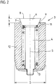
- Fig. 2
- in gleicher Schnittebene im Maßstab 20:1 ein einzelnes Entlüftungsventil mit einem angeschraubten Anschlage auf der kavernenabewandten Seite zur Begrenzung des Ventilöffnungsweges,
- Fig. 3
- in gleicher Schnittebene im Maßstab 20:1 ein einzelnes Entlüftungsventil mit einer Begrenzung des Ventilöffnungsweges durch ein definiertes Spiel in einem Schnappverschluß, zu dem eine als seperates Bauteil einzulegende Biegefeder gehört,
- Fig. 4a
- im gleichen Maßstab in der Draufsicht in ausgebautem Zustande die in
Figur 3 eingebaute Biegefeder - Fig. 4b
- in analoger Darstellungsweise eine andere Ausführung der in
Figur 3 einbaubaren Biegefeder und - Fig. 5
- in analoger Darstellung zur Figur 3 ein einzelnes Entlüftungsventil mit einer Begrenzung des Ventilöffnungsweges durch ein definiertes Spiel in einem Schnappverschluß, wobei hier jedoch die für einen Schnappverschluß nötige Einfederung nicht als Biegung einer seperaten Biegefeder sondern des unteren geschlitzten Endes des Ventilschaftes erreicht wird.
- Fig. 1a
- in longitudinal section, the left half of a shaped segment from the area molding the tread area of the tire with a valve in each vent hole, without a blank,
- Fig. 1b
- in longitudinal section the same half of the mold segment, but with an adjacent blank, which leads all vent valves into the closed position,
- Fig. 2
- in the same sectional plane on a scale of 20: 1, a single vent valve with a screwed-on stop on the side facing away from the cavern to limit the valve opening path,
- Fig. 3
- in the same sectional plane on a scale of 20: 1, a single vent valve with a limitation of the valve opening path through a defined play in a snap lock, which includes a spiral spring to be inserted as a separate component,
- Fig. 4a
- on the same scale, in a plan view, in the disassembled state, the spiral spring installed in FIG. 3
- Fig. 4b
- in an analogous representation another version of the spiral spring which can be installed in FIG. 3 and
- Fig. 5
- in an analogous representation to FIG. 3, a single vent valve with a limitation of the valve opening path through a defined play in a snap lock, but here the deflection required for a snap lock is achieved not as a bend of a separate spiral spring, but rather at the lower slotted end of the valve stem.
Figur 1a zeigt im Längsschnitt die linke Hälfte eines Formsegmentes 10 einer erfindungsgemäßen Vulkanisationsform 1; die Vulkanisationsform 1 ist in diesem Beispiel wie üblich - für die Erfindung aber nicht erforderlich - im Laufflächenbereich radial geteilt, die Segmente 10 sind also radial beweglich. Dieses Segment 10 stammt aus dem den Laufflächenbereich des Reifens abformenden Bereich. Üblicherweise weisen radial geteilte Formen 7 bis 13 Segmente 10 im Laufflächenbereich auf, in PKW-Reifenformen meistens 7 oder 9, in Leicht-LKW-Reifenformen meistens 9 oder 11 und in Schwer-LKW-Reifenformen meistens 11 oder 13.Figure 1a shows in longitudinal section the left half of a
Abweichend von der späteren Funktionsstellung des fertigen Reifens mit etwa horizontaler Stellung der Rotationsachse werden Vulkanisationsformen in der Regel in flacher Anordnung betrieben, also mit senkrechter Stellung der Rotationsachse; so sind die Rohlinge besser einlegbar und die vulkanisierten Reifen leichter zu entformen. Die beiden Seitenteile der Form heißen dementsprechend Formober- und Formunterseite.Deviating from the later functional position of the finished tire with an approximately horizontal position of the axis of rotation, vulcanization molds are generally operated in a flat arrangement, that is to say with the axis of rotation in a vertical position; the blanks are easier to insert and the vulcanized tires can be removed more easily. The two side parts of the mold are accordingly called the top and bottom of the mold.
Entlüftungsbedarf besteht sowohl für die radial beweglichen Segmente 10 wie für die beiden hier nicht dargestellten Seitenteile; die Anzahl der benötigten Entlüftungsöffnungen 2 pro Fläche ist jedoch in den Seitenteilen kleiner als in den Segmenten 10, weil dort die abzuformende Gestalt nicht so kompliziert ist. Vorzugsweise erfolgt die Entlüftung in den axial beweglichen Seitenteilen 10 über ebensolche Ventile 3 wie in den radial beweglichen Segmenten 10; weil abgesehen von der weniger dichten Anordnung der Entlüftungsöffnungen 2 keine Unterschiede zwischen der Entlüftung der radial beweglichen Segmente 10 und der axial beweglichen Seitenteile 10 bestehen, gilt das Bezugszeichen 10 für beide Segmentarten.There is a need for ventilation both for the radially
Wesentlich ist, daß in jeder Entlüftungsbohrung 2 ein Ventil 3 angeordnet ist. Das Formsegment ist in Fig. 1a dargestellt ohne anliegenden Rohling; infolgedessen sind alle Entlüftungsventile 3 im Zusammenspiel mit je einer schwachen Druckfeder 11, wie sie in der größeren Figur 2 deutlicher zu erkennen ist, geöffnet. Dabei ragen die Ventilteller 6, wie auch in Figur 2 erkennbar, in die Kaverne herein.It is essential that a
Die Rückholfeder zur Erreichung der Öffnungsstellung sollte so schwach wie möglich und so stark - unter Berücksichtigung von Gewicht, Reibung und Fertigungstoleranzen - wie nötig sein; um die Öffnungsstellung sicher zu erreichen, reicht es nach den bisherigen Versuchen aus, wenn die Vorspannung (genauer: die Vorstauchung) das 1,5-fache aus der Summe des Eigengewichtes des Ventileinsatzes und dem halben Federeigengewicht beträgt.The return spring to reach the opening position should be as weak as possible and as strong - taking into account weight, friction and manufacturing tolerances - as necessary; In order to reach the opening position safely, it is sufficient, according to previous tests, if the pre-tension (more precisely: the pre-compression) is 1.5 times the sum of the dead weight of the valve insert and half the spring weight.
In eine solche Form 1, wie in Fig. 1a gezeigt, mit offenen Entlüftungskanälen 2 infolge geöffenter Ventile 3 ist nunmehr in an sich bekannter Weise der Rohling eines Reifens 14 einzulegen.The blank of a tire 14 is now to be inserted in a
Figur 1b zeigt in analoger Darstellungsweise zur Figur 1a den Moment, wo - gegen Ende des "Resterhebens" - der Rohling des zu prägenden und zu vulkanisierenden Reifens 14 gerade in den Rillengründen der Form 1, die die erhabenden Stellen des entstehenden Laufflächenprofiles abformen und wo die meisten Entlüftungskanäle 2 kavernenseitig münden, zur Anlage kommt. Durch dieses Anlegen drückt der schon eine gewisse Gestaltfestigkeit aufweisende Kautschuk die Ventile 3 gegen den nur schwachen Widerstand der jeweiligen Druckfeder in die hier gezeigte geschlossene Stellung.Figure 1b shows in an analogous representation to Figure 1a the moment when - towards the end of the "residual lifting" - the blank of the tire 14 to be embossed and vulcanized, precisely in the groove bases of the
Unter "Resterheben" wird in der Reifenfachsprache der kleine Rest der gesamten Erhebung oder Bombage verstanden, der innerhalb der Vulkanisationsform durch Blähung erreicht wird und durch den die Profilformgebung erreicht oder - bei sehr tiefen Profilen und/oder sehr zugsteifen Bewehrungen - zumindest vollendet wird."Residual lifting" is understood in the tire technical language to mean the small remainder of the entire elevation or bombage, which is achieved by flatulence within the vulcanization mold and by which the profile shaping is achieved or - in the case of very deep profiles and / or very rigid reinforcements - is at least completed.
Figur 2 zeigt in gleicher Schnittebene wie Figur 1 im Maßstab 20:1 ein einzelnes Entlüftungsventil 3 mit einem Ventileinsatz 4. Der Ventileinsatz 4 umfaßt zumindest einen Ventilteller 6 und einen Ventilschaft 5. An einem Absatze des Ventiltellers 6 ist die Feder 11 zentriert. Zur Begrenzung des Ventilöffnungsweges ist auf der kavernenabewandten Seite ein ein Innengewinde aufweisender Anschlag 13 angeschraubt, zusammenwirkend mit einem Außengewinde auf dem entsprechenden Ende des Ventilschaftes 5.Figure 2 shows in the same sectional plane as Figure 1 on a scale of 20: 1 a
Der Ventilteller 6 weist eine an die Kaverne der Form angepaßte und demnach im wesentlichen plane Stirnfläche 8 auf. An diese legt sich der Reifenrohling beim Resterheben an. Der Ventilteller 6 ist im übrigen als Kegelstumpf 7 gestaltet passend im Durchmesser und im Kegelwinkel an die innenkegelige Fläche 9. Der Kegelwinkel zur strichpunktierten Längsachse des Ventileinsatzes sollte zwischen 15° und 60° liegen; gut bewährt hat sich der hier gezeigte Winkel von 22°.The
Zwecks besserer Logistik in der Formenfertigung, z. B. zwecks Outsourcen der gesamten Ventilherstellung an einen Ventilhersteller, empfiehlt es sich, wie hier gezeigt, jeden Ventileinsatz 4 in einem seperaten, im wesentlichen zylinderförmigen Gehäuse 12 anzuordnen. Zusammen mit der Druckfeder 11 und dem Anschlage 13 ergibt sich so eine Baueinheit, die alle Einzelteile des Ventiles 3 unverlierbar zusammenfaßt; ein solches Ventil 3 kann komplett vormontiert vom Ventilhersteller bezogen und vom Formenbauer in entsprechend vorbereitete Entlüftungsbohrungen von der Kaverne her eingesetzt werden.For better logistics in mold manufacturing, e.g. B. for the purpose of outsourcing the entire valve production to a valve manufacturer, it is recommended, as shown here, to arrange each
Das Einsetzen erfolgt vorzugsweise durch Einschlagen in eine enge Bohrung; so wird eine Preßpassung erreicht. Um einerseits einen hinreichend sicheren Halt und andererseits eine das Segment nicht verletzende Demontiermöglichkeit zu erhalten, hat es sich bewährt, bei einem Gehäuseaußendurchmesser D von 3,5 mm einen Bohrungsinnendurchmesser d (siehe Figur 1a) von 3,35 mm vorzusehen. Zwecks Erleichterung des Einschlagens weist das Gehäuse 12 am kavernenabgewandten Ende vorteilhafterweise eine Verjüngung auf.The insertion is preferably carried out by driving into a narrow hole; an interference fit is achieved. In order to obtain a sufficiently secure hold on the one hand and on the other hand a disassembly possibility that does not violate the segment, it has proven useful to provide an inner bore diameter d (see FIG. 1a) of 3.35 mm with an outer housing diameter D of 3.5 mm. In order to facilitate hammering in, the
Die Feder 11 ist vorzugsweise als Drahtwendelfeder ausgeführt mit etwa 10 freien Windungen und je einer auf Block anliegenden Windung an beiden Enden; bei einer steileren Wicklung der Feder erscheint es möglich, bei jedem Auf- und Zugehen eine kleine Verdrehung des Ventileinsatzes um die strichpunktierte Längsachse zu erreichen. So könnte noch länger anhaltend eine über dem Ventiltellerumfang besonders gleichmäßige Schließwirkung erreicht werden.The
Wird abweichend von Figur 2 das Ventil 3 gehäuselos ausgeführt, so ist selbstverständlich die innenkegelige Fläche 9 direkt an entsprechender Stelle des Formsegmentes einzubohren oder einzufräsen.If, in contrast to FIG. 2, the
Figur 3 zeigt in gleicher Schnittebene wie Figur 2 und im gleichen Maßstab 20:1 ein einzelnes Entlüftungsventil 3 mit einer Begrenzung des Ventilhubes h durch ein definiertes Spiel in einem Schnappverschluß, zu dem eine als seperates Bauteil einzulegende Biegefeder 16 gehört. In der weitestmöglich geöffenten Stellung, die hier gezeigt ist, schlägt der Ventilschaft 5 mit dar kavernenzugewandten Kegelstumpffäche 18.1 des Bundes 18, der am kavernenabgewandten Ende des Ventilschaftes 5 angeordnet ist, an die kavernenabgewandte Stirnfläche 16.3 der nach nach innenweisenden Schenkel 16.1 der Biegefeder 16.Figure 3 shows in the same sectional plane as Figure 2 and on the same scale 20: 1, a
Fig. 4a zeigt diese Biegefeder 16 einzeln im gleichen Maßstabe in der Draufsicht mit einem außen liegenden C-förmigen Teil 16.2, der so weit zusammenbiegbar ist, daß die Feder 16 von der kavernenabgewandten Seite her, also in Figur 3 von unten her, eingeführt werden kann in den Schacht des Gehäuses und sodann in der Nut 15 einschnappt, die auf der Innenseite des Ventilgehäuses 12 bzw. - bei gehäuseloser Ausführung - in der Bohrung im Segment in einer Ebene senkrecht zur Längsachse des Ventiles 3 angeordnet ist. Die Biegefeder 16 weist ferner nach innen weisende, elastisch biegsame Schenkel 16.1 auf, die so bemessen sind, daß sie nach ihrer Ausfederung in die in Figur 3 gezeigte Nut 17 des Ventilschaftes 5 eingreifen, also eng genug gestellt, daß nach Anlegen der kavernenzugewandten Fläche 18.1 des Bundes 18 an die kavernenabgewandte Fläche 16.3 der Feder 16 ein Widerstand gegen weiteres Herausziehen des Ventileinsatzes 4 auftritt; vorzugsweise sollten andererseits die Schenkel 16.1 so weit stehen, daß sich der Ventileinsatz 4 zwischen den Anschlägen 18.1 und 17.1 klemmfrei bewegen kann längs seiner strichpunktierten Längsachse.Fig. 4a shows this
Diese Schenkel 16.1 werden, wie Figur 3 zu entnehmen, beim Montieren des Ventilschaftes 5 von der Kaverne her gespreizt mittels einer vorauseilenden, also am kavernenabgewandten Ende angeordneten, konischen Fläche 18.2, die zu einer bundartigen Verdickung 18 des Ventilschaftes 5 am kavernenabgewandten Ende des Ventilschaftes 5 gehört. Nach Überwindung des dicksten Bereiches des Bundes 18 verengen sich die Schenkel 16.1 - auf der invers orientierten konischen Fläche 18.1 abgleitend - wieder so weit, daß der Ventilschaft 5 nur mit großer Kraft in Richtung der Kaverne (insbesondere mit einer größeren Kraft als der der Feder 11) in umgekehrter Richtung wieder heraus gezogen werden könnte. Um die Feder 16 stärker gegen ein Herausdrücken aus der Nut 15 bei Montage des Ventileinsatzes 4 zu sichern, kann von der kavernenabgewandten Seite her eine Hülse bis zur Feder eingepreßt oder -geschraubt werden.As can be seen in FIG. 3, these limbs 16.1 are spread from the cavern when the
Die nach innen weisenden Schenkel 16.1 greifen in eine Nut 17 des Ventilschaftes 5 ein, die (17) zur kavernenabgewandten Seite hin durch die konische Fläche 18.1 und zur kavernenzugewandten Seite hin durch die vorzugsweise plane Fläche 17.1 begrenzt ist. Die Nutweite w17 der Nut 17 ist um einen Betrag größer als die Federweite 16; dieser Betrag ist etwas größer als der Ventilhub h, sodaß in der geschlossenen Stellung des Ventiles 3 die Nutstirnfläche 17.1, die die Schließbewegung mitmacht, nicht bis zur kavernenzugewandten Stirnfläche 16.4 der Biegefeder 16 vordringt, wodurch eine Überbestimmung in der Wegbegrenzung des Ventileinsatzes 4 vermieden und somit sattes Einführen der außenkonischen Fläche 7 des Ventiltellers 6 in die innenkonische Fläche 9 möglich ist, was ein perfektes Schließen des Ventiles 3 und Versatzfreiheit zwischen der Stirnfläche 8 des Ventiltellers 6 und der umgebenden Kavernenoberfläche bewirkt. - Dies könnte theoretisch auch bei kleinerer Nutweite w17 erreicht werden, wenn die Nutweite w15 dann entsprechend größer wäre, kurzum gälte:![]()
![]()
Allerdings müßte dann auch der Außenteil 16.2 gegenüber dem Gehäuse 12 verschieblich sein, was aber zu einer Spieladdition auch in der Radialrichtung des Ventiles und zu einer Neigung zum Verkanten mit entsprechend streuenden Reibungsbeiwerten führt. Deshalb ist vorzugsweise w16 nur so geringfügig kleiner als w15, daß das zum Einsetzen nötige Spiel von ca. 20 µm erreicht ist. Obige Forderung vereinfacht sich dann zu:![]()
![]()
Figur 4b zeigt in analoger Darstellungsweise zu Figur 4a eine solche Variante der Biegefeder 16, bei der an den C-förmigen Teil, hier 16.5, nicht nach innen hin sondern nach außen hin Schenkel anschließen, die hier mit 16.6 bezeichnet sind. Die Schenkel 16.6 sollen in die Gehäusenut 15 eingreifen und der C-förmige Teil 16.5 in die Nut 17 des Ventilschaftes 5.FIG. 4b shows, in a manner analogous to that of FIG. 4a, such a variant of the
Figur 5 zeigt in analoger Darstellung zur Figur 3 ein einzelnes Entlüftungsventil 3 mit einer Begrenzung des Ventilöffnungsweges durch ein definiertes Spiel in einem Schnappverschluß, wobei auch hier die für einen Schnappverschluß erforderliche Einfederung als Biegung erreicht wird, jedoch nicht als Biegung einer seperaten Biegefeder sondern als Biegung des kavernenabgewandten, auf der Zeichnung also unten erscheinenden, geschlitzten Endes des Ventilschaftes 5.FIG. 5 shows, in an analogous representation to FIG. 3, a
Zur Kostenersparnis wird die Schlitzung durch nur einen Schlitz 19 erreicht, wie hier gezeigt. Dann muß der Schlitz 19 wie gezeigt ziemlich weit sein, um nicht nur in der gezeigten Längsschnittebene einen ausreichenden Einfederweg der beiden stehen bleibenden Zungen aufeinander zu beim Montieren und Demontieren durch die kavernenabgewandte Öffnung 12.1 des Gehäuses 12 hindurch zu ermöglichen sondern auch in der darauf senkrecht stehenden weiteren Längsschnittebene durch das Ventil 3. (Letztgenannte Schnittebene wäre für die gesamte Form 1 als eine Querschnittebene zu bezeichnen.) Es wäre aber auch eine schmalere Schlitzausführung möglich, wenn der Bund 18 in Schlitznähe nivelliert würde, also weniger hervorragte aus der übrigen Oberfläche des Schaftes 5, oder wenn statt des einen Schlitzes 19 zwei sich kreuzende Schlitze am kavernenabgewandten Ende des Schaftes 5 angeordnet würden.To save costs, the slitting is achieved by only one
Der Bund 18 am kavernenabgewandten Ende des Ventilschaftes 5 hat eine kavernenzugewandte Begrenzungsfläche 18.1. Sie dient als Anschlagfläche zur Begrenzung der Ventileröffnung und ist so plaziert, daß sie in der gewünschten Öffnungsstellung - der bei einem Ventiltellerdurchmesser von etwa 2,8 mm und einem Kegelwinkel zur Längsachse von 22° ein Ventilhub von etwa 0,5 mm entsprechen sollte, wie hier gezeigt - an die kavernenabgewandte Fläche des Gehäuses 12 - oder einer äquivalenten Fläche bei gehäuseloser Ausführung - anschlägt. Durch dieses Anschlagen ist der Öffnungsweg begrenzt.The
Die umgekehrte Bewegung, die Schließbewegung, wird in keiner Weise durch den Bund 18 begrenzt sondern allein durch das Auftreffen der außenkegeligen Fläche 7 des Ventiltellers 6 auf die innenkegelige Fläche 9.The reverse movement, the closing movement, is in no way limited by the
Zur Demontage eines solchen Ventileinsatzes 4 reicht infolge der gezeigten und bevorzugten konischen Ausführung der Anschlagfläche 18.1 ein kräftiges Ziehen am Ventilteller 6 in Richtung der Kaverne; ansonsten müßten mit der anderen Hand die stehenbleibenden Zungen des Ventilschaftes von Hand elastisch so weit zusammengebogen werden, daß sie die Öffnung 12.1 des Gehäuses 12 passieren können.To remove such a
Zur Montage ist analog eine konische Ausbildung auch der anderen Begrenzungsfläche 18.2 des Bundes 18 zweckmäßig; dann reicht ein kräftiges Hereindrücken.Analogous to the assembly, a conical design of the other boundary surface 18.2 of the
Die Tiefe des Schlitzes 19 bzw. der Schlitze am kavernenabgewandten Ende des Schaftes 5 ist klein genug, um im Zusammenspiel mit der so aufrecht erhaltenen Zungensteifigkeit einen ausreichenden Widerstand gegen unabsichliche Entfernung des Ventileinsatzes zu erhalten, andererseits groß genug, um die Zungen so biegeweich zu machen, daß eine Demontage erträglich leicht vonstatten geht.The depth of the
Die détaillierten Ausführungsbeispiele sollen dem Fachmann umfangreiche Kenntnis von der Erfindung geben; der Schutzumfang wird aber durch diese Détails aber nicht eingeschränkt. Kern der Erfindung ist allein, in jede der Hunderte von Entlüftungsbohrungen einer Reifenvulkanisationsform je ein Ventil einzusetzen, wobei jedes Ventil durch das Herannahen der Rohlingsoberfläche geschlossen wird und beim Entformen wieder geöffnet wird.The detailed exemplary embodiments are intended to give the person skilled in the art extensive knowledge of the invention; however, the scope of protection is not restricted by these details. The essence of the invention alone is to insert a valve into each of the hundreds of ventilation bores of a tire vulcanization mold, each valve being closed by the approach of the blank surface and being opened again during demolding.
Folgende Bezugszeichenliste ist Bestandteil der Beschreibung:The following list of reference symbols is part of the description:
- 11
- VulkanisationsformVulcanization form
- 22nd
- Entlüftungsbohrungen in 1Vent holes in 1
- 33rd
- Ventil, einzusetzen in 2Valve, to be used in 2
- 44th
- Ventileinsatz von 3Valve insert from 3
- 55
- Schaft von 4Shaft of 4
- 66
- Teller am kavernenzugewandten Ende von 4Plate at the end of 4 facing the cavern
- 77
- Kegelstumpf an der kavernenabgewandten Seite von 6Truncated cone on the side of 6 facing away from the cavern
- 88th
- im wesentlichen plane Fläche an der kavernenzugewandten Seite von 6essentially flat surface on the side of FIG. 6 facing the cavern
- 99
- innenkegelige Fläche in 10 bzw. 12 passend zu 7inner conical surface in 10 or 12 suitable for 7
- 1010th
- Segment von 1Segment of 1
- 1111
-
schwache Feder, Einsatz 4 von Ventil 3 in die Offenstellung drückendweak spring, pushing
insert 4 ofvalve 3 into the open position - 1212th
- Gehäuse von 3Housing of 3
- 1313
- Anschlag zur Bewegungsbegrenzung von 4Stop to limit movement of 4
- 1414
-
Luftreifen 15 Nut in der Innenseite des Gehäuses 12 auf der kavernenabgewandten Seite
Pneumatic tire 15 groove in the inside of thehousing 12 on the side facing away from the cavern - 1616
-
Biegefeder für Schnappverschluß
- 16.1 nach innen weisende Schenkel von 16 (4a)
- 16.2 äußerer, C-förmiger Teil der Biegefeder 16 (4a)
- 16.3 kavernenabgewandte Stirnfläche von 16
- 16.4 kavernenzugewandte Stirnfläche von 16
- 16.5 innerer, C-förmiger Teil anderer Biegefeder 16 (4b)
- 16.6 nach außen weisende Schenkel von 16 (4b)
- 16.1 inward-pointing legs of 16 (4a)
- 16.2 outer, C-shaped part of the spiral spring 16 (4a)
- 16.3 end face facing away from the cavern of 16
- 16.4 end face facing the cavern of 16
- 16.5 inner, C-shaped part of other spiral spring 16 (4b)
- 16.6 outward leg of 16 (4b)
- 1717th
-
Nut auf der Außenseite des Ventilschaftes 5 in der Nähe des kavernenabgewandten Endes
- 17.1 Stirnfläche zur Begrenzung von 17 auf kavernenzugewandter Seite
valve stem 5 near the end facing away from the cavern- 17.1 End face to limit 17 on the side facing the cavern
- 1818th
-
Bund am kavernenabgewandten Ende des Ventilschaftes 5
- 18.1 kavernenzugewandte Begrenzungsfläche des Bundes 18, gleichzeitig kavernenabgewandte Begrenzungsfläche der Nut 17, als Anschlagfläche dienend
- 18.2 kavernenabgewandte Begrenzungsfläche des Bundes 18, vorzugsweise kegelstumpfartig als Einführhilfe ausgebildet
cavern 5- 18.1 boundary surface of the
collar 18 facing the cavern, at the same time the boundary surface of thegroove 17 facing away from the cavern, serving as a stop surface - 18.2 boundary surface of the
collar 18 facing away from the cavern, preferably in the form of a truncated cone, as an insertion aid
- 1919th
-
Schlitz(e) durch das kavernenabgewandte Ende des Ventilschaftes 5 um eine Einfederung der Bundweite zu ermöglichenSlot (e) through the end of the
valve stem 5 facing away from the cavern in order to allow deflection of the waist width - DD
-
Außendurchmesser des Ventilgehäuses 12Outside diameter of the
valve housing 12 - dd
- InnendurchmesserInside diameter
- hH
- VentilhubValve lift
- w15w15
-
Weite der Nut 15Width of the
groove 15 - w16w16
-
Weite oder Dicke der Biegefeder 16Width or thickness of the
spiral spring 16 - w17w17
-
Weite der Nut 17Width of the
groove 17
Claims (13)
dadurch gekennzeichnet, daß jede der Hunderte von Entlüftungsbohrungen (2) ein Ventil (3) enthält, wobei jedes Ventil (3) so gestaltet ist, daß es durch das Herannahen der Rohlingsoberfläche geschlossen wird und beim Entformen wieder geöffnet wird.Vulcanization mold (1) for the production of tires (14) with a large number between 600 and 3,000 of ventilation holes (2)
characterized in that each of the hundreds of vent holes (2) contains a valve (3), each valve (3) being designed to be closed by the approach of the blank surface and to be opened again upon removal from the mold.
Applications Claiming Priority (2)
| Application Number | Priority Date | Filing Date | Title |
|---|---|---|---|
| DE19543276 | 1995-11-20 | ||
| DE19543276A DE19543276C1 (en) | 1995-11-20 | 1995-11-20 | Tire vulcanization mold with ventilation |
Publications (3)
| Publication Number | Publication Date |
|---|---|
| EP0774333A2 true EP0774333A2 (en) | 1997-05-21 |
| EP0774333A3 EP0774333A3 (en) | 1997-08-20 |
| EP0774333B1 EP0774333B1 (en) | 2001-01-31 |
Family
ID=7777956
Family Applications (1)
| Application Number | Title | Priority Date | Filing Date |
|---|---|---|---|
| EP96118423A Expired - Lifetime EP0774333B1 (en) | 1995-11-20 | 1996-11-16 | Tyre vulcanizing mould provided with venting means |
Country Status (19)
| Country | Link |
|---|---|
| EP (1) | EP0774333B1 (en) |
| JP (1) | JPH09141660A (en) |
| KR (1) | KR100484002B1 (en) |
| CN (1) | CN1066667C (en) |
| AT (1) | ATE199002T1 (en) |
| AU (1) | AU710458B2 (en) |
| BR (1) | BR9605614A (en) |
| CA (1) | CA2190720A1 (en) |
| CZ (1) | CZ291837B6 (en) |
| DE (2) | DE19543276C1 (en) |
| ES (1) | ES2155564T3 (en) |
| HU (1) | HU219783B (en) |
| MY (1) | MY117718A (en) |
| PL (1) | PL180855B1 (en) |
| PT (1) | PT774333E (en) |
| RU (1) | RU2189311C2 (en) |
| TR (1) | TR199600886A2 (en) |
| TW (1) | TW362061B (en) |
| ZA (1) | ZA967689B (en) |
Cited By (15)
| Publication number | Priority date | Publication date | Assignee | Title |
|---|---|---|---|---|
| GB2339163A (en) * | 1998-05-27 | 2000-01-19 | Dunlop Tyres Ltd | Mould vents |
| WO2003070443A1 (en) * | 2002-02-25 | 2003-08-28 | Kabushiki Kaisha Bridgestone | Rubber molded article vulcanizing mold, and method for cleaning the same |
| US6871831B1 (en) | 2003-12-19 | 2005-03-29 | The Goodyear Tire & Rubber Company | Mold vent |
| WO2009007493A1 (en) | 2007-07-11 | 2009-01-15 | Wd Racing Oy | Air venting valve of vulcanising mould |
| US7645131B2 (en) | 2006-03-03 | 2010-01-12 | Glebus Alloys Europe, S.R.O. | Venting valve to be used in venting bores of vulcanization molds |
| CN101323154B (en) * | 2007-06-13 | 2010-12-15 | 韩国轮胎株式会社 | Vent device of vulcanization mold |
| CN106141600A (en) * | 2016-07-01 | 2016-11-23 | 宜兴市凯诚模具有限公司 | A kind of processing technology of automobile tire mould |
| CN106738495A (en) * | 2017-02-08 | 2017-05-31 | 高密同创气门芯有限公司 | Exhaust apparatus, its assemble method and the tire-mold with the exhaust apparatus |
| WO2017211476A1 (en) | 2016-06-06 | 2017-12-14 | Continental Reifen Deutschland Gmbh | Ventilation unit for a vulcanization mold of a vehicle pneumatic tyre |
| US10118357B2 (en) | 2017-01-10 | 2018-11-06 | Continental Reifen Deutschland Gmbh | Holder for arranging a foil on a mold surface of a sidewall shell of a vulcanizing mold and a vulcanizing mold having such a holder |
| DE102017223310A1 (en) | 2017-12-20 | 2019-06-27 | Contitech Mgw Gmbh | Process for producing a shaped hollow body and apparatus for carrying out the process |
| DE102018203053A1 (en) | 2018-03-01 | 2019-09-05 | Continental Reifen Deutschland Gmbh | vulcanization mold |
| DE102018205607A1 (en) | 2018-04-13 | 2019-10-17 | Continental Reifen Deutschland Gmbh | vulcanization mold |
| WO2021144504A1 (en) * | 2020-01-16 | 2021-07-22 | Wd Racing Oy | Venting valve and method of mounting valve stem of venting valve |
| US11090842B2 (en) | 2017-04-12 | 2021-08-17 | Wd Racing Oy | Valve insert and air venting valve |
Families Citing this family (65)
| Publication number | Priority date | Publication date | Assignee | Title |
|---|---|---|---|---|
| GB9623770D0 (en) * | 1996-11-15 | 1997-01-08 | Sp Tyres Uk Ltd | Mould vents |
| GB9708584D0 (en) * | 1997-04-29 | 1997-06-18 | Sp Tyres Uk Ltd | Mould vents |
| DE19900596A1 (en) * | 1999-01-11 | 2000-07-13 | Dunlop Gmbh | Vulcanizing mold for technical rubber products, especially tires, has a two part shut off valve, one part of which has an outlet for air which closes when rubber approaches |
| ID27551A (en) | 1998-07-27 | 2001-04-12 | Dulop Gmbh | MOLD TIRE VULNIZATION WITH THE BARRIER COMPONENTS INSTALLED IN THE WIND DRILL HOLE |
| DE19833730C2 (en) * | 1998-07-27 | 2002-11-21 | Dunlop Gmbh | Tire vulcanization mold with valves installed in ventilation holes |
| DE10050195C1 (en) * | 2000-10-09 | 2002-02-28 | Fraunhofer Ges Forschung | Tyre valve removal method uses pulling device secured to part of valve projecting from tyre wall by providing joint connection |
| JP3589644B2 (en) * | 2000-12-07 | 2004-11-17 | 日本碍子株式会社 | Tire mold |
| JP2002240042A (en) * | 2001-02-15 | 2002-08-28 | Bridgestone Corp | Mold for vulcanizing and molding tire |
| KR100410785B1 (en) * | 2001-06-28 | 2003-12-18 | 한국타이어 주식회사 | Ventmember of vulcanizing mold |
| DE10155931A1 (en) * | 2001-11-14 | 2003-05-22 | Dunlop Gmbh | Vulcanization mold for the production of technical rubber products |
| KR20030069699A (en) * | 2002-02-22 | 2003-08-27 | 송영호 | Air plug of tire vulcanization mold |
| JP2004082692A (en) | 2002-06-28 | 2004-03-18 | Ngk Insulators Ltd | Flap vent piece installation assembly, flap vent piece installation structure and installation method, and tire molding mold |
| JP3717895B2 (en) * | 2002-07-04 | 2005-11-16 | 韓国タイヤ株式会社 | Tire vulcanization mold vent device |
| KR100498023B1 (en) * | 2002-12-02 | 2005-07-01 | 한국타이어 주식회사 | Vent member for tire vulcanizing mold |
| JP4277989B2 (en) * | 2003-07-07 | 2009-06-10 | 横浜ゴム株式会社 | Tire molds and plugs used for vent holes in tire molds |
| CN101076439B (en) | 2004-12-28 | 2011-08-24 | 倍耐力轮胎股份公司 | Vehicle tyre manufacturing method and apparatus |
| BRPI0419250B1 (en) * | 2004-12-28 | 2014-11-11 | Pirelli | "METHOD AND APPARATUS FOR MANUFACTURING TIRES FOR VEHICLE WHEELS". |
| BRPI0406493A (en) * | 2004-12-30 | 2006-09-05 | Unilever Nv | cleaning article device, equipment and manufacturing process having a fluid mass and having complex shapes and use of the cleaning article |
| US7654817B2 (en) * | 2005-01-28 | 2010-02-02 | Yugenkaisha T&K Corporation | Vent piece |
| KR101006894B1 (en) * | 2008-09-17 | 2011-01-12 | 한국타이어 주식회사 | Vent apparatus for tire vulcanizing mold |
| JP5195392B2 (en) * | 2008-12-18 | 2013-05-08 | 横浜ゴム株式会社 | Vent unit for vulcanization mold and vulcanization mold |
| DE102009021697B4 (en) * | 2009-02-17 | 2015-04-02 | Ftm Formentechnik U. Metallbau Gmbh | Cleaning of molds for the production of tire profiles |
| KR101338763B1 (en) | 2009-04-28 | 2013-12-06 | 아사히 가세이 겐자이 가부시키가이샤 | Device for forming thermosetting resin foam plate and method of manufacturing thermosetting resin foam plate |
| JP5593688B2 (en) * | 2009-12-02 | 2014-09-24 | 横浜ゴム株式会社 | Tire molding die plug, tire molding die and tire |
| DE102009059253B4 (en) | 2009-12-22 | 2020-12-03 | Continental Reifen Deutschland Gmbh | Vulcanization mold and use of a venting means as holding means for punched foils |
| JP2011198090A (en) | 2010-03-19 | 2011-10-06 | Fuji Xerox Co Ltd | Print job information management device, printer, and print job information management program |
| TW201132482A (en) * | 2010-03-23 | 2011-10-01 | Xiang-Hong You | Structure of degasing set of tire mold |
| DE102010043045A1 (en) * | 2010-10-28 | 2012-05-03 | Bayerische Motoren Werke Aktiengesellschaft | Molding tool for manufacturing fiber composite plastic parts, has cylinder comprising suction hole in fluid connection with cavity in piston position and locked against cavity in another piston position |
| DE102010060901B4 (en) * | 2010-11-30 | 2016-02-04 | Continental Reifen Deutschland Gmbh | Device for mounting ventilation valves in mold segments of a vulcanization mold for vehicle tires |
| US8834143B2 (en) * | 2011-02-24 | 2014-09-16 | The Yokohama Rubber Co., Ltd. | Tire vulcanization mold |
| DE102011050409A1 (en) | 2011-05-17 | 2012-11-22 | Continental Reifen Deutschland Gmbh | Vulcanization mold for vehicle tires |
| DE102011053207A1 (en) | 2011-09-02 | 2013-03-07 | Continental Reifen Deutschland Gmbh | Method for cleaning of molded or shaped segments of tire vulcanizing mold, involves testing venting units by ultrasonic-device on function from mold interior, where detected venting units are separated |
| DE102011053663A1 (en) | 2011-09-16 | 2013-03-21 | Continental Reifen Deutschland Gmbh | Vulcanization mold for vehicle tires and pneumatic vehicle tires, which is heat-pressed with an aforementioned Vulkanisierform |
| DE102012104500B4 (en) | 2012-05-24 | 2022-01-13 | Continental Reifen Deutschland Gmbh | Vulcanizing mold for vehicle tires |
| DE102012106809A1 (en) | 2012-07-26 | 2014-02-20 | Continental Reifen Deutschland Gmbh | Method and device for assisting the demoulding of a vulcanized pneumatic vehicle tire |
| DE102013108384A1 (en) | 2013-08-05 | 2015-02-05 | Continental Reifen Deutschland Gmbh | Vulcanization mold for vehicle tires and vehicle tires, which is heat-pressed with an aforementioned Vulkanisierform |
| DE102013110664A1 (en) | 2013-09-26 | 2015-03-26 | Continental Reifen Deutschland Gmbh | Venting means for a Vulkanisierform for vehicle tires |
| DE102013225160A1 (en) | 2013-12-06 | 2015-06-11 | Continental Reifen Deutschland Gmbh | Vulcanization mold for winter and all season vehicle tires |
| DE102013225280A1 (en) | 2013-12-09 | 2015-06-11 | Continental Reifen Deutschland Gmbh | Vulcanization mold for vehicle tires |
| FR3024068B1 (en) * | 2014-07-22 | 2016-08-12 | Michelin & Cie | MOLD FOR THE VULCANIZATION OF A PNEUMATIC COMPRISING MOBILE ELEMENTS OBTAINED BY LASER FRITTAGE |
| DE102014216869A1 (en) | 2014-08-25 | 2016-02-25 | Continental Reifen Deutschland Gmbh | vulcanizing |
| JP6453018B2 (en) * | 2014-10-01 | 2019-01-16 | 東洋ゴム工業株式会社 | Vulcanization molding equipment |
| KR101600324B1 (en) | 2014-11-10 | 2016-03-21 | 한국타이어 주식회사 | Spring Vent Apparatus of Tire Vulcanizing Mold |
| JP6514049B2 (en) * | 2015-06-09 | 2019-05-15 | 株式会社ブリヂストン | Mold for rubber article and method for manufacturing mold for rubber article |
| DE102015213027A1 (en) | 2015-07-13 | 2017-01-19 | Continental Reifen Deutschland Gmbh | Vulcanization mold for vehicle tires |
| DE102016206949B4 (en) * | 2016-04-25 | 2021-11-11 | Vitesco Technologies GmbH | Process for the production of an assembly, vulcanization tool and assembly |
| KR101689650B1 (en) * | 2016-06-02 | 2016-12-27 | 주식회사 메가산업 | Spring vent of tire vulcanizing mold |
| DE102016209912A1 (en) | 2016-06-06 | 2017-12-07 | Continental Reifen Deutschland Gmbh | Venting unit for a vulcanization mold of a pneumatic vehicle tire |
| DE102016209916A1 (en) | 2016-06-06 | 2017-12-07 | Continental Reifen Deutschland Gmbh | Venting unit for a vulcanization mold of a pneumatic vehicle tire |
| DE102016209910A1 (en) | 2016-06-06 | 2017-12-07 | Continental Reifen Deutschland Gmbh | Venting unit for a vulcanization mold of a pneumatic vehicle tire |
| USD825721S1 (en) | 2016-07-11 | 2018-08-14 | Wd Racing Oy | Valve insert |
| IT201600126146A1 (en) * | 2016-12-14 | 2018-06-14 | Bridgestone Corp | VULCANIZATION MOLD OF A TREAD STRIP |
| FR3080559B1 (en) * | 2018-04-30 | 2021-04-30 | Michelin & Cie | MOLDING ELEMENT WITH AIR EXHAUST SLOT AND MICRO-MOLDING SECTOR |
| JP7083700B2 (en) * | 2018-05-31 | 2022-06-13 | Toyo Tire株式会社 | Manufacturing method of tire vulcanization mold and pneumatic tire |
| FI128331B (en) * | 2018-10-11 | 2020-03-31 | Wd Racing Oy | Venting valve |
| DE102018218010A1 (en) | 2018-10-22 | 2020-04-23 | Contitech Mgw Gmbh | Device for producing a shaped hollow body |
| CZ308197B6 (en) * | 2018-12-21 | 2020-06-24 | GOTTSCHOL ALCUILUX CZ, spol. s r. o. | Venting valve for venting holes of vulcanizing moulds |
| CN109435293A (en) * | 2018-12-27 | 2019-03-08 | 高密同创气门芯有限公司 | A kind of exhaust apparatus and tire-mold |
| JP6741097B1 (en) * | 2019-02-25 | 2020-08-19 | 横浜ゴム株式会社 | Tire vulcanizing apparatus and method |
| CN109940794A (en) * | 2019-04-30 | 2019-06-28 | 山东豪迈机械科技股份有限公司 | A kind of exhaust apparatus and tire-mold |
| CN110027138B (en) * | 2019-06-12 | 2019-12-13 | 山东豪迈机械科技股份有限公司 | Exhaust device and tire mold |
| KR102086810B1 (en) * | 2019-08-29 | 2020-03-09 | 이춘성 | Gas outlet of mold core |
| FI128951B (en) | 2020-01-16 | 2021-03-31 | Wd Racing Oy | Venting valve and method of mounting valve stem of venting valve |
| FR3107202B1 (en) | 2020-02-19 | 2024-02-16 | Gottschol Alcuilux Cz | Deaeration valve on vulcanization mold discharge ports |
| FR3137867A1 (en) | 2022-07-13 | 2024-01-19 | Compagnie Generale Des Etablissements Michelin | System and Method for Acquisition and Determination of Valve Axes in Tire Vulcanization Molds |
Citations (26)
| Publication number | Priority date | Publication date | Assignee | Title |
|---|---|---|---|---|
| US3377662A (en) | 1965-04-20 | 1968-04-16 | Bridgestone Tire Co Ltd | Metal mold having vent plug means for shaping a plastic article and vulcanizing a rubber article |
| DE1933816A1 (en) | 1969-07-03 | 1971-01-14 | Herbert Maschf L | Radial vulcanizing mould for vehicle - tyres |
| DE2200314A1 (en) | 1972-01-05 | 1973-07-12 | Continental Gummi Werke Ag | Injection mould tool - for rubber or plastics articles, having automatic air bubble eliminator |
| DE2210099A1 (en) | 1972-03-02 | 1973-09-06 | Dunlop Ag | Moulding tyres - and evacuating air between carcase and mould |
| JPS5191423A (en) | 1975-02-07 | 1976-08-11 | ||
| JPS51119776A (en) | 1975-04-14 | 1976-10-20 | Bridgestone Tire Co Ltd | Metal mold for vulcanizing tire |
| DE2524538A1 (en) | 1975-06-03 | 1976-12-16 | Continental Gummi Werke Ag | Injection mould for articles of rubber or synthetics - ensures timely cutting of connection to vacuum by deflection |
| DE3142288A1 (en) | 1981-10-24 | 1983-05-05 | Continental Gummi-Werke Ag, 3000 Hannover | Injection mould for producing rubber or plastic articles |
| US4573894A (en) | 1984-11-23 | 1986-03-04 | The B. F. Goodrich Company | Apparatus for ventless tire molding |
| US4597929A (en) | 1984-11-23 | 1986-07-01 | The B. F. Goodrich Company | Method for ventless tire molding and tire resulting therefrom |
| EP0228652A2 (en) | 1985-12-27 | 1987-07-15 | Dow Corning Corporation | Multiple release mold coating |
| US4691431A (en) | 1984-10-31 | 1987-09-08 | Sumitomo Rubber Industries, Ltd. | Method of making a metal mold for tire vulcanization |
| US4708609A (en) | 1984-03-22 | 1987-11-24 | Bridgestone Corporation | Tire manufacturing mold |
| DE3622598A1 (en) | 1986-07-05 | 1988-04-28 | Elastogran Polyurethane Gmbh | Moulding tool for multicomponent plastics, in particular polyurethane |
| US4812281A (en) | 1987-12-14 | 1989-03-14 | The Goodyear Tire & Rubber Company | Pressurization of tire mold vents |
| EP0311550A2 (en) | 1987-10-06 | 1989-04-12 | The Goodyear Tire & Rubber Company | Mold vent plug |
| US4881881A (en) | 1988-02-08 | 1989-11-21 | The Uniroyal Goodrich Tire Company | Plug-resistant arch-vents for a tire mold |
| DE3903899A1 (en) | 1989-02-10 | 1990-08-16 | Continental Ag | Vulcanising mould for rubber articles |
| DE3914649A1 (en) | 1989-05-02 | 1990-11-08 | Az Formen & Maschbau Gmbh | VENTED TIRE SHAPE |
| EP0414630A1 (en) | 1989-08-23 | 1991-02-27 | The Goodyear Tire & Rubber Company | Detachment of tires from molds |
| EP0440040A2 (en) | 1990-01-31 | 1991-08-07 | Maschinenbau Herbert GmbH & Co. | Profiled segment for tyre-vulcanising mould |
| EP0451832A2 (en) | 1990-04-13 | 1991-10-16 | PIRELLI COORDINAMENTO PNEUMATICI S.p.A. | A mold and method of tyre curing and method for mold manufacturing |
| EP0468154A2 (en) | 1990-07-27 | 1992-01-29 | Uniroyal Goodrich Licensing Services, Inc. | Improved tire mold, method and tire |
| EP0518899A1 (en) | 1990-03-07 | 1992-12-23 | Fct Sa | System for evacuating air from moulds for vulcanizing tyres. |
| US5283022A (en) | 1989-09-29 | 1994-02-01 | The Uniroyal Goodrich Tire Company | Restrictor for tire mold vent passage and method of use |
| EP0591745A2 (en) | 1992-10-07 | 1994-04-13 | Compagnie Generale Des Etablissements Michelin-Michelin & Cie | Tyre mould and method for moulding tyres |
Family Cites Families (11)
| Publication number | Priority date | Publication date | Assignee | Title |
|---|---|---|---|---|
| US2865052A (en) * | 1955-10-04 | 1958-12-23 | Hooker Chemical Corp | Vented mold for plastic materials |
| GB922788A (en) * | 1958-08-25 | 1963-04-03 | Dunlop Rubber Co | Venting means for moulds |
| NL7610516A (en) * | 1975-09-30 | 1977-04-01 | Sekisui Plastics | STEAM DRAINING DEVICE. |
| US4021168A (en) * | 1976-02-12 | 1977-05-03 | The General Tire & Rubber Company | Tire mold having washered nails inserted in the vents |
| US4492554A (en) * | 1980-08-26 | 1985-01-08 | Corn States Metal Fabricators, Inc. | Valve unit for a mold vent |
| US4347212A (en) * | 1980-08-26 | 1982-08-31 | Corn States Metal Fabricators, Inc. | Method for forming a tire |
| US4436497A (en) * | 1982-10-27 | 1984-03-13 | The Goodyear Tire & Rubber Company | Mold and vent plug therefor |
| JPS6147216A (en) * | 1984-08-11 | 1986-03-07 | Bridgestone Corp | Manufacture of rubber or plastic molding and mold employed in said manufacturing method |
| US4759701A (en) * | 1987-09-18 | 1988-07-26 | Corn States Metal Fabricators, Inc. | Venting unit for a rubber article forming mold having vents |
| DE4007049A1 (en) * | 1990-03-07 | 1991-09-12 | Hoechst Ag | METHOD FOR PRODUCING 3'-AMINOPROPYL-2-SULFATOETHYL SULPHONE |
| KR970006948Y1 (en) * | 1994-04-12 | 1997-07-11 | 금호타이어 주식회사 | Air vent device of vulcanizing molds |
-
1995
- 1995-11-20 DE DE19543276A patent/DE19543276C1/en not_active Expired - Lifetime
-
1996
- 1996-08-05 CZ CZ19962308A patent/CZ291837B6/en not_active IP Right Cessation
- 1996-08-06 HU HU9602172A patent/HU219783B/en unknown
- 1996-08-12 PL PL96315650A patent/PL180855B1/en unknown
- 1996-08-16 JP JP8216372A patent/JPH09141660A/en active Pending
- 1996-08-28 RU RU96116933/12A patent/RU2189311C2/en active
- 1996-09-12 ZA ZA967689A patent/ZA967689B/en unknown
- 1996-09-13 MY MYPI96003805A patent/MY117718A/en unknown
- 1996-10-23 TW TW085112998A patent/TW362061B/en not_active IP Right Cessation
- 1996-11-07 TR TR96/00886A patent/TR199600886A2/en unknown
- 1996-11-15 AU AU71784/96A patent/AU710458B2/en not_active Expired
- 1996-11-16 AT AT96118423T patent/ATE199002T1/en active
- 1996-11-16 PT PT96118423T patent/PT774333E/en unknown
- 1996-11-16 ES ES96118423T patent/ES2155564T3/en not_active Expired - Lifetime
- 1996-11-16 DE DE59606405T patent/DE59606405D1/en not_active Expired - Lifetime
- 1996-11-16 EP EP96118423A patent/EP0774333B1/en not_active Expired - Lifetime
- 1996-11-19 BR BR9605614A patent/BR9605614A/en not_active IP Right Cessation
- 1996-11-19 CA CA002190720A patent/CA2190720A1/en not_active Abandoned
- 1996-11-20 KR KR1019960055536A patent/KR100484002B1/en not_active IP Right Cessation
- 1996-11-20 CN CN96119203A patent/CN1066667C/en not_active Expired - Lifetime
Patent Citations (26)
| Publication number | Priority date | Publication date | Assignee | Title |
|---|---|---|---|---|
| US3377662A (en) | 1965-04-20 | 1968-04-16 | Bridgestone Tire Co Ltd | Metal mold having vent plug means for shaping a plastic article and vulcanizing a rubber article |
| DE1933816A1 (en) | 1969-07-03 | 1971-01-14 | Herbert Maschf L | Radial vulcanizing mould for vehicle - tyres |
| DE2200314A1 (en) | 1972-01-05 | 1973-07-12 | Continental Gummi Werke Ag | Injection mould tool - for rubber or plastics articles, having automatic air bubble eliminator |
| DE2210099A1 (en) | 1972-03-02 | 1973-09-06 | Dunlop Ag | Moulding tyres - and evacuating air between carcase and mould |
| JPS5191423A (en) | 1975-02-07 | 1976-08-11 | ||
| JPS51119776A (en) | 1975-04-14 | 1976-10-20 | Bridgestone Tire Co Ltd | Metal mold for vulcanizing tire |
| DE2524538A1 (en) | 1975-06-03 | 1976-12-16 | Continental Gummi Werke Ag | Injection mould for articles of rubber or synthetics - ensures timely cutting of connection to vacuum by deflection |
| DE3142288A1 (en) | 1981-10-24 | 1983-05-05 | Continental Gummi-Werke Ag, 3000 Hannover | Injection mould for producing rubber or plastic articles |
| US4708609A (en) | 1984-03-22 | 1987-11-24 | Bridgestone Corporation | Tire manufacturing mold |
| US4691431A (en) | 1984-10-31 | 1987-09-08 | Sumitomo Rubber Industries, Ltd. | Method of making a metal mold for tire vulcanization |
| US4597929A (en) | 1984-11-23 | 1986-07-01 | The B. F. Goodrich Company | Method for ventless tire molding and tire resulting therefrom |
| US4573894A (en) | 1984-11-23 | 1986-03-04 | The B. F. Goodrich Company | Apparatus for ventless tire molding |
| EP0228652A2 (en) | 1985-12-27 | 1987-07-15 | Dow Corning Corporation | Multiple release mold coating |
| DE3622598A1 (en) | 1986-07-05 | 1988-04-28 | Elastogran Polyurethane Gmbh | Moulding tool for multicomponent plastics, in particular polyurethane |
| EP0311550A2 (en) | 1987-10-06 | 1989-04-12 | The Goodyear Tire & Rubber Company | Mold vent plug |
| US4812281A (en) | 1987-12-14 | 1989-03-14 | The Goodyear Tire & Rubber Company | Pressurization of tire mold vents |
| US4881881A (en) | 1988-02-08 | 1989-11-21 | The Uniroyal Goodrich Tire Company | Plug-resistant arch-vents for a tire mold |
| DE3903899A1 (en) | 1989-02-10 | 1990-08-16 | Continental Ag | Vulcanising mould for rubber articles |
| DE3914649A1 (en) | 1989-05-02 | 1990-11-08 | Az Formen & Maschbau Gmbh | VENTED TIRE SHAPE |
| EP0414630A1 (en) | 1989-08-23 | 1991-02-27 | The Goodyear Tire & Rubber Company | Detachment of tires from molds |
| US5283022A (en) | 1989-09-29 | 1994-02-01 | The Uniroyal Goodrich Tire Company | Restrictor for tire mold vent passage and method of use |
| EP0440040A2 (en) | 1990-01-31 | 1991-08-07 | Maschinenbau Herbert GmbH & Co. | Profiled segment for tyre-vulcanising mould |
| EP0518899A1 (en) | 1990-03-07 | 1992-12-23 | Fct Sa | System for evacuating air from moulds for vulcanizing tyres. |
| EP0451832A2 (en) | 1990-04-13 | 1991-10-16 | PIRELLI COORDINAMENTO PNEUMATICI S.p.A. | A mold and method of tyre curing and method for mold manufacturing |
| EP0468154A2 (en) | 1990-07-27 | 1992-01-29 | Uniroyal Goodrich Licensing Services, Inc. | Improved tire mold, method and tire |
| EP0591745A2 (en) | 1992-10-07 | 1994-04-13 | Compagnie Generale Des Etablissements Michelin-Michelin & Cie | Tyre mould and method for moulding tyres |
Cited By (20)
| Publication number | Priority date | Publication date | Assignee | Title |
|---|---|---|---|---|
| GB2339163B (en) * | 1998-05-27 | 2002-12-24 | Dunlop Tyres Ltd | Mould vents |
| GB2339163A (en) * | 1998-05-27 | 2000-01-19 | Dunlop Tyres Ltd | Mould vents |
| WO2003070443A1 (en) * | 2002-02-25 | 2003-08-28 | Kabushiki Kaisha Bridgestone | Rubber molded article vulcanizing mold, and method for cleaning the same |
| US7360749B2 (en) | 2002-02-25 | 2008-04-22 | Kabushiki Kaisha Bridgestone | Rubber molded article vulcanizing mold, and method for cleaning the same |
| US6871831B1 (en) | 2003-12-19 | 2005-03-29 | The Goodyear Tire & Rubber Company | Mold vent |
| US7645131B2 (en) | 2006-03-03 | 2010-01-12 | Glebus Alloys Europe, S.R.O. | Venting valve to be used in venting bores of vulcanization molds |
| CN101323154B (en) * | 2007-06-13 | 2010-12-15 | 韩国轮胎株式会社 | Vent device of vulcanization mold |
| WO2009007493A1 (en) | 2007-07-11 | 2009-01-15 | Wd Racing Oy | Air venting valve of vulcanising mould |
| US8287260B2 (en) | 2007-07-11 | 2012-10-16 | Wd Racing Oy | Air venting valve of vulcanising mould |
| US8801996B2 (en) | 2007-07-11 | 2014-08-12 | Wd Racing Oy | Air venting valve of vulcanising mould |
| WO2017211476A1 (en) | 2016-06-06 | 2017-12-14 | Continental Reifen Deutschland Gmbh | Ventilation unit for a vulcanization mold of a vehicle pneumatic tyre |
| CN106141600A (en) * | 2016-07-01 | 2016-11-23 | 宜兴市凯诚模具有限公司 | A kind of processing technology of automobile tire mould |
| US10118357B2 (en) | 2017-01-10 | 2018-11-06 | Continental Reifen Deutschland Gmbh | Holder for arranging a foil on a mold surface of a sidewall shell of a vulcanizing mold and a vulcanizing mold having such a holder |
| CN106738495A (en) * | 2017-02-08 | 2017-05-31 | 高密同创气门芯有限公司 | Exhaust apparatus, its assemble method and the tire-mold with the exhaust apparatus |
| CN106738495B (en) * | 2017-02-08 | 2023-08-11 | 高密同创气门芯有限公司 | Exhaust device, assembly method thereof and tire mold with exhaust device |
| US11090842B2 (en) | 2017-04-12 | 2021-08-17 | Wd Racing Oy | Valve insert and air venting valve |
| DE102017223310A1 (en) | 2017-12-20 | 2019-06-27 | Contitech Mgw Gmbh | Process for producing a shaped hollow body and apparatus for carrying out the process |
| DE102018203053A1 (en) | 2018-03-01 | 2019-09-05 | Continental Reifen Deutschland Gmbh | vulcanization mold |
| DE102018205607A1 (en) | 2018-04-13 | 2019-10-17 | Continental Reifen Deutschland Gmbh | vulcanization mold |
| WO2021144504A1 (en) * | 2020-01-16 | 2021-07-22 | Wd Racing Oy | Venting valve and method of mounting valve stem of venting valve |
Also Published As
| Publication number | Publication date |
|---|---|
| RU2189311C2 (en) | 2002-09-20 |
| AU710458B2 (en) | 1999-09-23 |
| DE59606405D1 (en) | 2001-03-08 |
| KR100484002B1 (en) | 2005-08-29 |
| HU219783B (en) | 2001-08-28 |
| PL315650A1 (en) | 1997-05-26 |
| TW362061B (en) | 1999-06-21 |
| CZ291837B6 (en) | 2003-06-18 |
| MY117718A (en) | 2004-07-31 |
| AU7178496A (en) | 1997-05-29 |
| KR970025900A (en) | 1997-06-24 |
| PL180855B1 (en) | 2001-04-30 |
| EP0774333A3 (en) | 1997-08-20 |
| ZA967689B (en) | 1997-05-27 |
| CN1066667C (en) | 2001-06-06 |
| MX9605708A (en) | 1997-09-30 |
| HUP9602172A2 (en) | 1997-06-30 |
| ATE199002T1 (en) | 2001-02-15 |
| CZ230896A3 (en) | 1997-07-16 |
| CN1154291A (en) | 1997-07-16 |
| JPH09141660A (en) | 1997-06-03 |
| CA2190720A1 (en) | 1997-05-21 |
| DE19543276C1 (en) | 1997-02-06 |
| PT774333E (en) | 2001-07-31 |
| HUP9602172A3 (en) | 1998-03-02 |
| BR9605614A (en) | 1998-08-18 |
| ES2155564T3 (en) | 2001-05-16 |
| TR199600886A2 (en) | 1997-06-21 |
| EP0774333B1 (en) | 2001-01-31 |
| HU9602172D0 (en) | 1996-09-30 |
Similar Documents
| Publication | Publication Date | Title |
|---|---|---|
| DE19543276C1 (en) | Tire vulcanization mold with ventilation | |
| DE60114275T2 (en) | Method for producing a reinforced thermoplastic workpiece and mold | |
| EP0548703B1 (en) | Method and apparatus for making tyres | |
| EP0458250B1 (en) | Method and device for ejecting a tamper-evident ring of a closure cap | |
| DE60215514T2 (en) | tire vulcanizing | |
| EP0036908B1 (en) | Safety ring for pneumatic vehicle tyres | |
| EP3463837B1 (en) | Matrix for a tire mould, tire mould and method of manufacturing | |
| DE60304884T2 (en) | SEGMENTED TIRE FOR REDUCING GRAT | |
| DE2531601B2 (en) | Anti-skid bolts for pneumatic tires of motor vehicles | |
| EP1004123B1 (en) | Method and mould for producing umbrella-type insulators | |
| DE2640640A1 (en) | TIRE SHAPE TO ACHIEVE A TREAD PATTERN | |
| DE102012101526A1 (en) | tire vulcanizing | |
| WO2015082102A1 (en) | Vulcanizing mould for winter and all-season vehicle tyres, method for producing the vulcanizing mould and pneumatic vehicle tyre | |
| EP1518653B1 (en) | Blocking members for vent bores in vulcanisation molds and vulcanisation mold provided with such blocking member | |
| DE1231421B (en) | Venting device for a vulcanizing mold | |
| DE3311856A1 (en) | INNER TUBE FOR TIRES AND DEVICE FOR THEIR PRODUCTION | |
| DE4341683A1 (en) | Mould segment for tyre manufacture | |
| DE3442021C2 (en) | ||
| DE2210099A1 (en) | Moulding tyres - and evacuating air between carcase and mould | |
| DE1805178A1 (en) | Vulcanising mould for tyres | |
| DE466984C (en) | Device for the production of undercut recesses in molded blocks made of plastic material | |
| EP3727782B1 (en) | Method for producing a molded hollow body, and device for carrying out the method | |
| CH703721A1 (en) | Blow mold with a liftable molding. | |
| EP2570248B1 (en) | Vulcanisation mould for vehicle tyres | |
| DE2305199A1 (en) | Pneumatic tyre for cars etc - with treaded support surface and embedded reinforcing layers at ridges of tread |
Legal Events
| Date | Code | Title | Description |
|---|---|---|---|
| PUAI | Public reference made under article 153(3) epc to a published international application that has entered the european phase |
Free format text: ORIGINAL CODE: 0009012 |
|
| AK | Designated contracting states |
Kind code of ref document: A2 Designated state(s): AT BE CH DE DK ES FI FR GB GR IE IT LI LU NL PT SE |
|
| PUAL | Search report despatched |
Free format text: ORIGINAL CODE: 0009013 |
|
| AK | Designated contracting states |
Kind code of ref document: A3 Designated state(s): AT BE CH DE DK ES FI FR GB GR IE IT LI LU NL PT SE |
|
| 17P | Request for examination filed |
Effective date: 19970714 |
|
| 17Q | First examination report despatched |
Effective date: 19990809 |
|
| GRAG | Despatch of communication of intention to grant |
Free format text: ORIGINAL CODE: EPIDOS AGRA |
|
| GRAG | Despatch of communication of intention to grant |
Free format text: ORIGINAL CODE: EPIDOS AGRA |
|
| GRAH | Despatch of communication of intention to grant a patent |
Free format text: ORIGINAL CODE: EPIDOS IGRA |
|
| GRAH | Despatch of communication of intention to grant a patent |
Free format text: ORIGINAL CODE: EPIDOS IGRA |
|
| GRAA | (expected) grant |
Free format text: ORIGINAL CODE: 0009210 |
|
| AK | Designated contracting states |
Kind code of ref document: B1 Designated state(s): AT BE CH DE DK ES FI FR GB GR IE IT LI LU NL PT SE |
|
| PG25 | Lapsed in a contracting state [announced via postgrant information from national office to epo] |
Ref country code: IE Free format text: LAPSE BECAUSE OF FAILURE TO SUBMIT A TRANSLATION OF THE DESCRIPTION OR TO PAY THE FEE WITHIN THE PRESCRIBED TIME-LIMIT Effective date: 20010131 |
|
| REF | Corresponds to: |
Ref document number: 199002 Country of ref document: AT Date of ref document: 20010215 Kind code of ref document: T |
|
| REG | Reference to a national code |
Ref country code: CH Ref legal event code: EP |
|
| REG | Reference to a national code |
Ref country code: IE Ref legal event code: FG4D Free format text: GERMAN |
|
| REF | Corresponds to: |
Ref document number: 59606405 Country of ref document: DE Date of ref document: 20010308 |
|
| ITF | It: translation for a ep patent filed |
Owner name: ING. C. GREGORJ S.P.A. |
|
| PG25 | Lapsed in a contracting state [announced via postgrant information from national office to epo] |
Ref country code: DK Free format text: LAPSE BECAUSE OF FAILURE TO SUBMIT A TRANSLATION OF THE DESCRIPTION OR TO PAY THE FEE WITHIN THE PRESCRIBED TIME-LIMIT Effective date: 20010430 |
|
| PG25 | Lapsed in a contracting state [announced via postgrant information from national office to epo] |
Ref country code: GR Free format text: LAPSE BECAUSE OF FAILURE TO SUBMIT A TRANSLATION OF THE DESCRIPTION OR TO PAY THE FEE WITHIN THE PRESCRIBED TIME-LIMIT Effective date: 20010504 |
|
| REG | Reference to a national code |
Ref country code: ES Ref legal event code: FG2A Ref document number: 2155564 Country of ref document: ES Kind code of ref document: T3 |
|
| GBT | Gb: translation of ep patent filed (gb section 77(6)(a)/1977) |
Effective date: 20010426 |
|
| ET | Fr: translation filed | ||
| REG | Reference to a national code |
Ref country code: PT Ref legal event code: SC4A Free format text: AVAILABILITY OF NATIONAL TRANSLATION Effective date: 20010426 |
|
| REG | Reference to a national code |
Ref country code: IE Ref legal event code: FD4D |
|
| PG25 | Lapsed in a contracting state [announced via postgrant information from national office to epo] |
Ref country code: LI Free format text: LAPSE BECAUSE OF NON-PAYMENT OF DUE FEES Effective date: 20011130 Ref country code: CH Free format text: LAPSE BECAUSE OF NON-PAYMENT OF DUE FEES Effective date: 20011130 |
|
| PLBE | No opposition filed within time limit |
Free format text: ORIGINAL CODE: 0009261 |
|
| STAA | Information on the status of an ep patent application or granted ep patent |
Free format text: STATUS: NO OPPOSITION FILED WITHIN TIME LIMIT |
|
| REG | Reference to a national code |
Ref country code: GB Ref legal event code: IF02 |
|
| 26N | No opposition filed | ||
| REG | Reference to a national code |
Ref country code: CH Ref legal event code: PL |
|
| REG | Reference to a national code |
Ref country code: PT Ref legal event code: PC4A Owner name: CONTINENTAL REIFEN DEUTSCHLAND GMBH, DE Effective date: 20101207 |
|
| REG | Reference to a national code |
Ref country code: GB Ref legal event code: 732E Free format text: REGISTERED BETWEEN 20110310 AND 20110316 |
|
| REG | Reference to a national code |
Ref country code: NL Ref legal event code: SD Effective date: 20110318 |
|
| REG | Reference to a national code |
Ref country code: ES Ref legal event code: PC2A Owner name: CONTINENTAL REIFEN DEUTSCHLAND GMBH Effective date: 20120118 |
|
| PGFP | Annual fee paid to national office [announced via postgrant information from national office to epo] |
Ref country code: DE Payment date: 20141130 Year of fee payment: 19 |
|
| REG | Reference to a national code |
Ref country code: DE Ref legal event code: R231 Ref document number: 59606405 Country of ref document: DE |
|
| PG25 | Lapsed in a contracting state [announced via postgrant information from national office to epo] |
Ref country code: DE Free format text: LAPSE BECAUSE OF THE APPLICANT RENOUNCES Effective date: 20150605 |
|
| REG | Reference to a national code |
Ref country code: FR Ref legal event code: PLFP Year of fee payment: 20 |
|
| PGFP | Annual fee paid to national office [announced via postgrant information from national office to epo] |
Ref country code: FI Payment date: 20151111 Year of fee payment: 20 Ref country code: IT Payment date: 20151125 Year of fee payment: 20 Ref country code: GB Payment date: 20151118 Year of fee payment: 20 Ref country code: LU Payment date: 20151119 Year of fee payment: 20 |
|
| PGFP | Annual fee paid to national office [announced via postgrant information from national office to epo] |
Ref country code: AT Payment date: 20151119 Year of fee payment: 20 Ref country code: NL Payment date: 20151118 Year of fee payment: 20 Ref country code: FR Payment date: 20151119 Year of fee payment: 20 Ref country code: SE Payment date: 20151118 Year of fee payment: 20 Ref country code: PT Payment date: 20151116 Year of fee payment: 20 Ref country code: BE Payment date: 20151118 Year of fee payment: 20 Ref country code: ES Payment date: 20151111 Year of fee payment: 20 |
|
| REG | Reference to a national code |
Ref country code: NL Ref legal event code: MK Effective date: 20161115 |
|
| REG | Reference to a national code |
Ref country code: GB Ref legal event code: PE20 Expiry date: 20161115 |
|
| REG | Reference to a national code |
Ref country code: AT Ref legal event code: MK07 Ref document number: 199002 Country of ref document: AT Kind code of ref document: T Effective date: 20161116 |
|
| PG25 | Lapsed in a contracting state [announced via postgrant information from national office to epo] |
Ref country code: GB Free format text: LAPSE BECAUSE OF EXPIRATION OF PROTECTION Effective date: 20161115 |
|
| REG | Reference to a national code |
Ref country code: ES Ref legal event code: FD2A Effective date: 20170224 |
|
| PG25 | Lapsed in a contracting state [announced via postgrant information from national office to epo] |
Ref country code: PT Free format text: LAPSE BECAUSE OF EXPIRATION OF PROTECTION Effective date: 20161124 |
|
| PG25 | Lapsed in a contracting state [announced via postgrant information from national office to epo] |
Ref country code: ES Free format text: LAPSE BECAUSE OF EXPIRATION OF PROTECTION Effective date: 20161117 |